
온도조절기 접점: 바이메탈 작동과 은접점 조립 기술
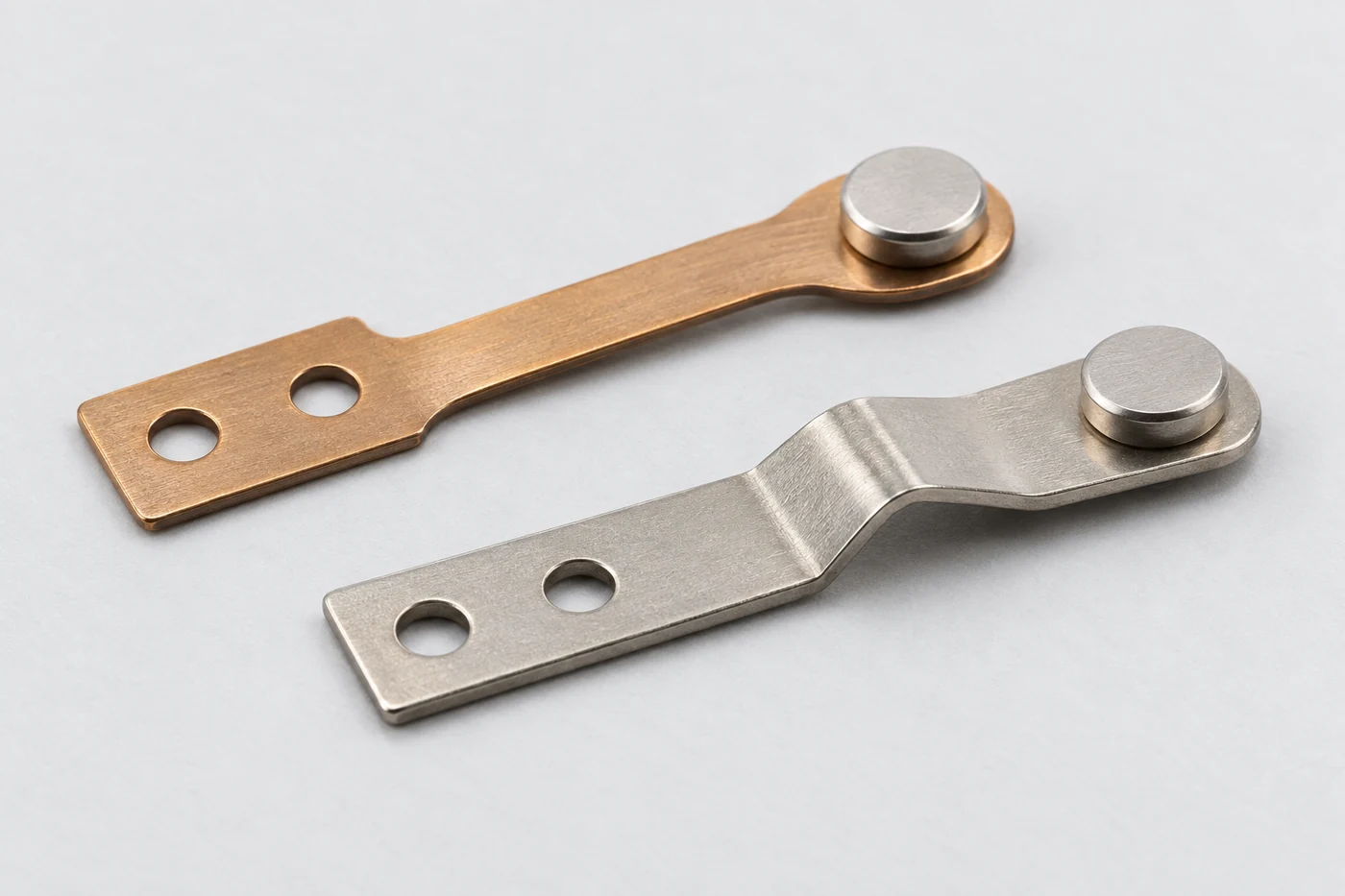
온도조절기 접점은 설정된 온도에서 전류를 연결하거나 끊는 작은 전기 부품입니다. 바이메탈이 온도 변화를 움직임으로 바꾸면, 은계 접점과 프레스 가동편이 그 움직임을 안정적인 통전과 차단으로 이어 줍니다. 히터·전열기기·온도 보호 장치에서 접점 재료, 접촉력, 조립 높이와 열 전달 조건을 함께 관리해야 하는 이유입니다.
온도조절기 접점의 품질은 은접점 하나의 재질만으로 결정되지 않습니다. 접점이 정확히 마주 보는 위치, 가동편의 탄성, 리벳팅·용접부의 상태, 개폐 속도와 온도 복귀 특성이 하나의 조립체 안에서 맞아야 합니다. 소재 선정부터 프레스 가공, 접점 결합, 온도 교정과 부하 내구 평가까지 제조 흐름에 따라 살펴봅니다.
01온도 감지와 전류 개폐를 잇는 접점 조립체
바이메탈과 은접점의 서로 다른 기능
바이메탈은 열팽창 특성이 다른 금속층을 결합한 감온 부품입니다. 온도가 변하면 두 층의 길이 변화 차이로 휘어지며, 형상과 지지 조건에 따라 연속 변위 또는 스냅 동작을 만듭니다. 은접점은 상대 접점과 맞닿아 전류를 전달하고 떨어지면서 회로를 끊는 기능면입니다. 감온 재료와 접점 재료를 구분해야 온도 특성과 전기 수명을 각각 관리할 수 있습니다.
스냅 디스크형에서는 바이메탈 디스크의 움직임이 절연 작동봉을 통해 별도의 접점 가동편에 전달되는 구성이 사용됩니다. 이때 디스크는 감온·구동을 맡고, 전류는 단자와 접점 가동편을 따라 흐릅니다. 반면 바이메탈 자체가 통전 경로에 포함되는 구조도 있으므로, 회로도와 단면에서 기계적 전달 경로와 전류 경로를 따로 확인해야 합니다.
| 구성 부품 | 주요 기능 | 조립 관리 항목 |
|---|---|---|
| 바이메탈 감온부 | 온도 변화를 변위·작동력으로 변환 | 감온 위치, 지지 상태, 작동 방향 |
| 절연 작동봉·전달부 | 움직임 전달과 전기적 분리 | 길이, 유격, 접촉 위치 |
| 접점 가동편·고정편 | 접촉 위치·힘과 전류 경로 형성 | 기준면, 조립 높이, 탄성 변위 |
| 은계 접점 | 통전 및 개폐 시 접촉 기능 | 재질, 접촉면, 부착 상태 |
| 절연 지지부·단자 | 부품 위치 유지와 외부 연결 | 체결, 절연 간격, 열 전달 |
작은 부품이 만드는 전체 작동 특성
절연 작동봉의 길이가 달라지면 접점이 움직이기 시작하는 위치가 변하고, 가동편의 성형 각도가 달라지면 닫힌 상태의 접촉력이 변합니다. 접점 머리 높이와 지지부 체결 상태도 같은 치수 사슬에 들어갑니다. 개별 부품 치수와 완성 조립체의 작동 온도·접촉 상태를 연결하는 검사가 필요합니다.
02스냅 디스크형과 판형 바이메탈의 작동 구조
빠른 전환을 만드는 스냅 디스크
스냅 디스크는 온도 변화에 따라 곡률 상태가 급격히 바뀌면서 작동봉을 움직입니다. 정상 닫힘형에서는 접점 가동편이 고정접점에 눌려 통전하다가, 상승 온도에서 디스크가 전환되어 접점을 벌리는 구성이 가능합니다. 자동 복귀형은 냉각 후 복귀 온도에 도달하면 다시 닫힙니다. 상승 시 닫히는 형식은 접점 배치와 작동 방향이 다릅니다.
스냅 동작은 천천히 변하는 온도를 빠른 접점 이동으로 바꾸는 데 유리합니다. 다만 디스크의 전환과 접점의 실제 분리는 별개의 움직임입니다. 전달부 유격, 가동편 강성, 접점 고착과 움직이는 질량에 따라 결과가 달라지므로, 디스크가 튀는 모습만으로 개폐 성능을 판단하지 않습니다.
판형 감온부와 복귀 방식의 구분
판형 바이메탈을 사용하는 온도조절기는 온도에 따른 휨을 접점이나 별도의 스냅 기구에 전달합니다. 조절 나사나 지지 위치로 기계적 조건을 바꾸는 설계도 있습니다. 판형이라고 모두 느린 개폐 방식인 것은 아니며, 감온부 형상과 접점 전환 기구를 나누어 살펴야 합니다.
| 구분 | 작동 특징 | 제작·검사 관점 |
|---|---|---|
| 스냅 디스크형 | 디스크의 곡률 전환으로 빠른 변위 발생 | 디스크 지지, 작동봉 길이, 접점 변위 연결 |
| 판형 바이메탈 방식 | 감온 판재의 휨을 접점 기구에 전달 | 유효 길이, 고정 조건, 교정 후 잔류 변형 |
| 자동 복귀형 | 온도 하강 또는 상승 후 지정 조건에서 복귀 | 작동·복귀 온도와 반복 편차 |
| 수동 복귀형 | 온도 조건 외에 리셋 조작 필요 | 리셋 기구와 복귀 허용 조건 |
자동 복귀형 제어기, 수동 복귀형 온도 제한기, 일회성 온도 퓨즈는 복귀 기능과 보호 역할이 다릅니다. 같은 온도에서 회로를 끊더라도 서로 그대로 대체할 수 없습니다. 접점 조립체는 완성 장치의 제어·보호 기능에 맞는 기구와 검사 조건으로 개발해야 합니다.
화살표 키로 시점 조절
가동편의 탄성으로 두 접점이 맞닿습니다. 바이메탈 디스크는 작동봉을 통해 기계적 변위를 전달하며, 접점의 통전 경로와 분리됩니다.
전기적으로 분리된 바이메탈 디스크와 절연 작동봉이 상시 닫힘형 접점 가동편을 여닫는 구조
03은계 접점 재료의 특성과 부하 적합성
전도성과 개폐 내구성의 조합
은은 전기·열 전도성이 우수해 전기접점의 기본 재료로 사용됩니다. 그러나 온도조절기 접점은 전류가 흐르는 동안의 저항뿐 아니라 개폐 아크, 접점 용착, 재료 이동과 표면 피막의 영향을 받습니다. 순은에 가까운 소재를 선택하는 것과 개폐 부하에 맞는 은계 복합재를 선택하는 것은 서로 다른 설계 판단입니다.
| 재료군 | 주요 특성 | 선정 시 검토 항목 |
|---|---|---|
| Ag 계열 | 높은 전도성과 열 전달 특성 | 접촉력, 표면 피막, 부하에 따른 용착·마모 |
| AgNi 계열 | 은 기지에 니켈을 분산시킨 접점 재료 | 니켈 함량·분포, 가공성, 부하별 내구 특성 |
| AgSnO₂ 계열 | 산화주석 분산으로 내융착·내아크 특성 조정 | 돌입전류, 개폐 에너지, 저에너지 접촉 안정성 |
| 복합 구조 접점 | 기능 재료와 지지 재료를 결합 | 접촉층 위치·두께, 접합 계면, 후속 부착 공정 |
접점 소재와 실제 전기 조건의 연결
AgNi는 니켈 함량과 미세조직에 따라 전도성, 경도와 성형성이 달라집니다. AgSnO₂ 역시 산화물의 함량·분포와 제조 상태가 중요합니다. 두 재료를 단순히 상위·하위 등급으로 나누기보다 정격 부하, 돌입전류, 접촉력, 개폐 횟수와 표면 조건을 함께 놓고 비교해야 합니다.
히터의 저항 부하와 모터·코일의 유도 부하는 개폐 시 전기 조건이 다릅니다. 전원 입력부의 용량성 부하도 투입 순간 큰 전류를 만들 수 있습니다. 특히 AC 정격을 같은 수치의 DC 정격으로 옮겨 쓰면 안 됩니다. DC는 주기적인 전류 영점을 기대할 수 없으므로 접점 간극과 아크 차단 조건을 별도로 검토합니다.
미소 전류를 검출하는 회로에서는 표면 피막과 오염에 대한 민감도가 커집니다. 큰 전류의 개폐 내구성이 좋은 재료가 낮은 전압·전류에서도 항상 안정적인 것은 아닙니다. 재료명, 조성, 접촉면 상태와 부하 조건을 묶어 관리해야 소재 변경의 영향을 확인할 수 있습니다.
04접촉면·머리·다리로 나누는 접점 형상
작동면과 체결부의 역할 분리
리벳형 온도조절기 접점은 상대 접점에 닿는 머리와 가동편에 끼워 체결하는 다리로 구성할 수 있습니다. 평면 접촉면과 낮은 원통형 머리를 적용하면 접촉면의 높이, 방향과 가장자리 상태를 명확히 관리할 수 있습니다. 모서리 반경과 기능면의 곡률은 접촉 위치와 면 방향에 영향을 주므로 도면에서 구분해 지정합니다.
접점 머리 외경이 커도 실제 전류가 지나는 미세 접촉부는 하중과 표면 상태에 따라 형성됩니다. 따라서 외경만 키워 접촉저항이나 수명을 보장할 수 없습니다. 상대 접점과의 중심 어긋남, 가동편의 각도, 닫힐 때의 면 방향을 함께 관리해야 합니다. 접촉면 형상이 다른 제품은 해당 도면의 곡률과 방향을 따릅니다.
재료 배치와 다리 성형 여유
솔리드 접점은 머리와 다리에 같은 접점 재료를 사용하는 방식입니다. 클래드 구조는 필요한 위치에 기능 재료를 두고 지지 재료와 결합합니다. 접촉층의 두께나 체적 비율을 모든 제품에 공통으로 적용하지 않으며, 개폐 마모와 제조 공정에 맞는 층 배치를 도면에서 정합니다. 성형과 부착 뒤에도 기능층의 위치와 접합 계면이 유지되는지 확인해야 합니다.
다리의 길이와 구멍의 조합은 리벳팅에 사용할 재료량과 조립 위치를 결정합니다. 돌출량이 부족하면 체결 형성이 제한되고, 과하면 가동편 변형이나 치우친 성형을 만들 수 있습니다. 리벳팅 뒤쪽은 기본적으로 체결부이며, 별도의 기능 설계가 없는 한 두 번째 접촉면으로 해석하지 않습니다.

05프레스 가동편의 탄성과 통전 특성
소재 상태와 유효 스프링 형상
접점 가동편은 전류를 전달하면서 접촉력을 만드는 판스프링입니다. 동합금 등의 소재를 고를 때 전도성만 보지 않고 항복 특성, 피로와 응력완화, 사용 온도 및 접합 공정을 함께 검토합니다. 동일한 합금명이라도 조질과 압연 상태가 달라지면 성형 후 복원과 잔류 변형이 달라질 수 있습니다.
단순 외팔보에 가까운 형상에서는 폭, 두께, 유효 길이가 굽힘 강성을 좌우합니다. 특히 두께 변화는 스프링 강성에 크게 작용하며, 통전 단면적도 바꿉니다. 실제 가동편의 슬롯·단차·절곡부와 지지 조건은 단순 보의 거동에서 벗어나게 하므로, 완성 형상에서 하중–변위 관계를 확인해야 합니다.
일정한 조립 변위를 유지해도 사용 온도와 시간에 따라 응력이 완화되어 접촉력이 줄 수 있습니다. 반복 굽힘에 따른 피로와 구분해 조질, 온도와 유지 시간 조건으로 검토합니다. 초기 접촉력뿐 아니라 열 이력 이후 남는 힘을 확인해야 장기간 닫혀 있는 접점의 상태를 평가할 수 있습니다.
절단면과 성형 기준면의 관리
프레스 가공에서는 압연 방향과 절곡 방향, 굽힘 반경, 절단면 상태를 함께 관리합니다. 버가 절연 부품을 향하거나 접점 주변에 남으면 조립 방해와 이물 발생의 원인이 됩니다. 접점 구멍 주변의 변형과 절곡 후 비틀림은 접촉 위치를 바꾸므로, 외곽 치수와 함께 기능 기준면을 검사합니다.
가동편을 눌러 평평하게 만든 상태의 치수와 자유 상태의 치수는 다릅니다. 검사 도면에는 지지 위치, 구속 상태, 측정 하중을 정해야 합니다. 접점 부착과 후속 열공정까지 마친 가동편의 접촉력도 확인하면, 프레스 단품에서 보이지 않던 조립 변형과 탄성 변화를 구분할 수 있습니다.
06리벳팅과 용접으로 완성하는 접점 결합
가동편을 지지하는 리벳팅 공정
리벳팅은 가동편의 구멍에 접점 다리를 넣고 반대쪽을 성형해 고정하는 방식입니다. 공구는 접점 머리를 안정적으로 받치고 가동편 주변을 지지해야 합니다. 접촉면에 이물이나 공구 형상이 전사되지 않도록 하면서, 다리가 균일하게 퍼지고 부품이 치우치지 않는 성형 조건을 확보합니다.
리벳 머리가 충분히 커 보이는 것만으로 결합 품질을 판정하지 않습니다. 접점의 들뜸·회전, 가동편 휨, 접촉면 기울기와 연결부 저항을 함께 확인합니다. 성형 하중을 해제한 뒤 접점 높이와 가동편의 자유 형상을 재측정해야 탄성 복원 이후의 실제 조립 상태를 볼 수 있습니다.
용접부와 접촉 기능면의 분리
용접형은 접점의 배면과 지지판 사이에 접합부를 형성합니다. 저항용접에서는 전류가 흐르는 경로와 가압 상태, 접합 돌기 또는 배면 형상이 열 발생 위치를 좌우합니다. 접점 재료와 캐리어의 조합에 맞는 배면 구조를 사용하고, 용접 전 표면 상태와 전극 정렬을 관리해야 합니다.
용접 열이 과도하게 퍼지면 가동편의 탄성 상태나 접점 위치가 바뀔 수 있습니다. 반대로 결합이 불충분하면 흔들림이나 전기·열 전달 불안정이 생깁니다. 공정 조건 기록에 단면과 기계적 결합 검사, 접점 위치 및 완성 조립체의 전기 검사를 연결해 관리합니다.
| 결합 방식 | 우선 관리 항목 | 완성 후 확인 |
|---|---|---|
| 리벳팅 | 구멍·다리 조합, 돌출량, 지지와 공구 정렬 | 들뜸·회전, 머리 형상, 가동편 휨 |
| 저항용접 | 배면 구조, 표면 상태, 가압·전류·시간 | 접합부, 변형, 기능면 손상 |
| 공통 | 접점 위치와 공정 이력 | 접촉 높이·힘, 전류 경로와 저항 |
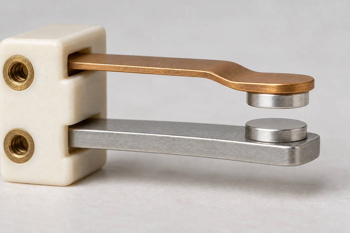
화살표 키로 시점 조절
접점은 접촉 기능을, 가동편은 통전과 탄성 기능을 맡습니다. 절연 지지부는 두 단자의 전기적 분리와 조립 높이를 유지합니다.
접점, 프레스 가동편과 절연 지지부의 기능을 분리해 보여주는 조립 구조
07접촉력·간극·오버트래블의 균형
첫 접촉 이후에 형성되는 접촉력
두 접점이 처음 닿는 위치와 충분한 접촉력을 얻는 위치는 같지 않습니다. 첫 접촉 후 기구가 더 움직이면서 가동편에 탄성 변형이 쌓이면 접촉력이 형성됩니다. 이 추가 이동을 접점 추종량 또는 오버트래블과 연결해 관리합니다. 접촉면은 맞닿은 상태를 유지하고 스프링이나 지지 기구의 변형이 추가 이동을 받아들입니다.
접촉력이 너무 작으면 진동과 표면 피막의 영향을 받기 쉽고, 접촉저항과 발열이 불안정해질 수 있습니다. 과도한 힘은 감온부가 이겨야 할 하중을 키우고 가동편 응력과 마모를 증가시킵니다. 접점 소재, 기구 변위와 사용 온도를 함께 고려해 닫힌 상태의 힘과 개방에 필요한 힘을 정합니다.
개방 간극과 정렬의 기능 치수
개방 간극은 전류 차단과 절연 상태에 영향을 주지만, 간극 하나로 정격을 결정할 수 없습니다. 부하의 전압·전류와 AC/DC 조건, 아크 경로, 절연물과 주변 금속의 배치까지 함께 검토해야 합니다. 접점이 벌어진 뒤 충분한 분리 상태를 유지하는지도 실제 기구에서 확인합니다.
접점 중심이 어긋나거나 면이 기울면 접촉 자국이 한쪽에 집중될 수 있습니다. 일부 기구에서 사용하는 제어된 미끄럼 접촉은 표면 피막을 다루는 기능이지만, 조립 비틀림으로 생긴 불규칙한 긁힘과는 다릅니다. 접촉 위치, 닫힘 방향, 오버트래블과 복귀 여유를 조립 도면의 기능 치수로 관리합니다.
화살표 키로 시점 조절
가동 접촉면과 고정 접촉면 사이에 간격이 있습니다. 지지 위치가 이동하면서 두 기능면이 가까워집니다.
접촉 후 추가 이동이 접점의 겹침이 아닌 가동편의 탄성 변형으로 이어지는 과정
08열 전달과 자기발열이 만드는 작동 조건
감온부까지 이어지는 열의 경로
온도조절기는 감온부가 도달한 온도에 반응합니다. 히터 표면, 장착 브래킷, 금속 캡과 바이메탈 사이에는 열 전달 경로가 있으며, 접촉 상태와 재료·두께·주변 공기 흐름이 응답에 영향을 줍니다. 같은 감온 부품도 장착면과 체결 상태가 달라지면 열을 받아들이는 속도가 달라질 수 있습니다.
주변 공기 온도, 대상 표면 온도와 바이메탈 온도는 항상 같지 않습니다. 빠른 가열에서는 대상과 감온부 사이의 온도 차이가 커질 수 있으므로, 시험 온도를 어느 위치에서 읽었는지와 가열 조건을 함께 기록합니다. 감온 디스크가 외기에 노출되는 구조와 캡 내부에 보호되는 구조도 열 응답이 달라, 구조에 맞는 장착·교정 조건이 필요합니다.
접촉저항이 온도 동작에 미치는 영향
통전 중에는 접점과 가동편, 단자와 접합부에서 전력 손실이 발생합니다. 저항성 발열은 전류의 제곱과 저항에 비례하는 I²R 관계로 증가하므로, 접촉 상태가 나빠져 저항이 커지면 주변 온도와 별개로 조립체에 열이 더해집니다. 그 열이 바이메탈에 전달되는 정도에 따라 작동 시점도 영향을 받을 수 있습니다.
감온 디스크가 전류 경로와 전기적으로 분리되어 있어도 주변 접점과 단자에서 발생한 열은 전달될 수 있습니다. 반대로 바이메탈 자체가 통전하는 구조는 전류에 의한 자기발열을 더욱 직접적으로 고려해야 합니다. 무통전 온도 교정, 통전 온도 상승과 실제 장착 상태의 동작 확인을 나누어 보면 열 원인을 구분하기 쉽습니다.
09온도 히스테리시스와 접점 바운스
작동 온도와 복귀 온도의 차이
자동 복귀형 온도조절기는 가열 중 접점이 전환되는 온도와 냉각 중 다시 전환되는 온도가 다릅니다. 이 온도 차이가 열적 히스테리시스 또는 동작 차이로 관리됩니다. 각 설정 온도의 허용오차, 감온부의 열지연, 장치 전체의 온도 오버슈트와는 구분하는 값입니다. 경계 부근의 작은 온도 변화로 계속 켜졌다 꺼지는 현상을 줄이며, 제어 대상의 열용량과 발열·냉각 조건에 맞춰 검토합니다.
히스테리시스는 온도 축의 특성이고, 접점 바운스는 한 번의 전환 순간에 접점이 부딪힌 뒤 짧게 반복 분리·접촉하는 기계·전기 현상입니다. 두 현상을 같은 진동으로 다루면 원인을 놓치기 쉽습니다. 스냅 기구로 빠르게 작동해도 충돌 후 반동이 생길 수 있으므로 바운스가 자동으로 사라지는 것은 아닙니다.
전환 순간의 아크와 재료 손상
접점이 전류를 끊거나 다시 붙는 동안 생기는 아크는 국부 가열과 재료 이동을 만들 수 있습니다. 반복 개폐 후 접촉면에 돌기와 함몰이 생기거나 용착 흔적이 남으면 재료뿐 아니라 바운스, 접촉력, 개방 속도와 전기 부하를 함께 살펴야 합니다. 표면만 다시 다듬어 원인을 해결했다고 판단하지 않습니다.
동작 온도와 복귀 온도는 온도 기록으로, 바운스와 개방 과정은 전압·전류 파형 및 필요에 따른 변위 기록으로 확인합니다. 센서 위치, 부하와 기구 구속 조건을 맞추어 비교하면 열 제어의 변동과 접점 운동의 불안정을 분리할 수 있습니다.
10표면·도금·세척으로 유지하는 접촉 안정성
기능면과 단자 표면처리의 구분
접점 기능면, 리벳팅 배면, 외부 연결 단자는 서로 다른 표면 요구를 가집니다. 단자의 접속성이나 보관 내식성을 위한 도금이 은계 접점의 개폐 특성을 그대로 대신하지는 않습니다. 도금이 필요한 영역과 접촉 기능을 유지해야 하는 영역을 도면에서 구분하고, 후속 성형·용접이 층에 미치는 영향을 검토합니다.
접촉면의 색과 광택만으로 접촉저항을 판정할 수 없습니다. 은계 표면은 주변 환경의 영향을 받아 피막이 생길 수 있으며, 그 영향은 전압·전류와 접촉력에 따라 달라집니다. 외관 검사와 전기적 검사를 연결하고, 소재 등급과 공급 상태를 유지하면서 표면 변화를 판단합니다.
공정 잔류물과 입자의 관리
프레스유, 세척 잔류물, 섬유와 금속 입자는 접촉면과 절연부에 남을 수 있습니다. 일반 가공유를 접점 윤활제로 간주해서는 안 됩니다. 윤활이 필요한 설계에서는 접점용으로 검증한 재료와 도포량을 지정하고, 휘발·이행과 열 영향을 포함해 완성 조립체에서 적합성을 확인합니다.
세척 방법은 접점과 가동편뿐 아니라 절연체, 접착부와 실링 구조에도 맞아야 합니다. 닦기나 연마를 무조건 추가하면 기능층이나 형상을 바꿀 수 있습니다. 공정 잔류물 제거, 충분한 건조, 접촉면 비접촉 취급과 포장을 연결해 검사 후 재오염을 줄이는 방식으로 관리합니다.
11치수·접촉력·접촉저항의 단계별 검사
형상 검사와 하중 검사의 연결
검사는 접점 단품, 프레스 가동편, 결합품과 완성 조립체로 나누면 원인 추적이 쉬워집니다. 접점 단품에서는 머리 높이와 다리·배면 상태를, 가동편에서는 구멍 위치와 성형 기준을 확인합니다. 결합 후에는 기울기와 변형을, 완성 조립체에서는 닫힘 위치·개방 간극·접촉력을 확인합니다.
| 검사 단계 | 주요 확인 항목 | 측정 조건 |
|---|---|---|
| 접점·가동편 단품 | 접점 형상, 구멍, 버, 성형 높이 | 기능 기준면과 자유·구속 상태 |
| 접점 결합품 | 들뜸, 기울기, 가동편 변형, 결합 상태 | 공정 하중 해제 후 측정 |
| 접점 조립체 | 접촉 위치, 간극, 힘–변위 관계 | 닫힘·개방 위치와 지지 조건 |
| 전기적 연결 | 저항과 측정값의 반복성 | 전류 경로, 측정점, 전류·전압 조건 |
저에너지 검사와 4선식 측정
4선식 측정은 전류를 흘리는 선과 전압을 읽는 선을 분리해 리드·접속선 저항의 영향을 줄입니다. 하지만 전압 측정점을 어디에 두는지에 따라 접점 계면만 볼 수도 있고 단자·가동편·접합부를 포함한 전체 경로를 볼 수도 있습니다. 측정 구간을 도면에 표시하고, 접촉력과 조립 상태를 일정하게 유지해야 비교가 가능합니다.
표면 피막을 평가하는 저에너지 검사는 시험 전류와 개방 전압을 제한해 측정 자체가 피막을 바꾸는 영향을 줄입니다. 높은 전류 시험을 먼저 하면 초기 피막 상태가 달라질 수 있으므로 검사 순서도 정해야 합니다. 미소 저항 측정에서는 열기전력, 온도 안정과 계측기 분해능을 함께 고려하며, 적용 조건에 맞는 보정·전류 반전 방법을 사용합니다.
12온도 교정과 부하 내구 평가
작동·복귀 온도의 반복 확인
온도 교정은 감온부가 놓이는 위치와 열 전달 조건, 가열·냉각 방식이 정해진 상태에서 수행합니다. 기준 온도 센서의 위치, 온도 변화 속도, 안정화 조건과 통전 여부를 함께 기록해야 합니다. 접점이 전환된 순간의 온도를 읽는 절차가 달라지면 같은 부품도 다른 결과로 보일 수 있습니다.
자동 복귀형은 작동 온도와 복귀 온도, 그 차이와 반복 편차를 각각 확인합니다. 수동 복귀형은 정해진 온도 상태에서 리셋 가능 여부와 리셋 후 접촉 상태를 검증합니다. 초기 교정이 맞아도 체결 변화나 가동편의 응력완화, 반복 개폐로 특성이 달라질 수 있으므로 내구 후 온도·기계·전기 특성을 다시 비교합니다.
무부하 동작과 실제 부하 개폐의 구분
무부하 반복 동작은 기구와 온도 전환을 살펴보는 데 유용하지만 전기적 개폐 수명을 대신하지 않습니다. 부하 내구는 전압·전류, 주파수, 저항·유도·용량성 조건, 투입 전류와 작동 주기를 정한 상태에서 수행해야 합니다. 시험 중 접촉저항과 온도 상승, 용착·개방 불량 및 표면 변화를 함께 추적하면 손상 경로를 파악할 수 있습니다.
완성 온도조절기의 정격과 사용 조건은 해당 제품의 사양과 적용 평가에 따라 결정됩니다. 부품 소재가 같거나 외형이 비슷하다는 이유로 다른 제품의 정격·인증·수명을 옮기지 않습니다. 접점 제작 요구에는 목표 부하와 작동 환경, 내구 후 허용 변화와 판정 기준을 함께 포함하는 것이 효과적입니다.
13도면·공정·로트 관리로 연결하는 제작 품질
기능을 기준으로 정리하는 제작 도면
온도조절기 접점 도면은 접점 외경·높이와 가동편 외형에 그치지 않아야 합니다. 감온부의 작동 방향, 상대 접점 위치, 조립 기준면과 하중 조건을 연결하면 가공 치수가 실제 기능으로 이어집니다. 접촉면과 접합면, 절연체를 향하는 면을 구분하면 버 방향, 표면 처리와 공구 지지 요구도 명확해집니다.
| 정의 항목 | 도면·사양에 포함할 내용 |
|---|---|
| 접점 재료 | 등급, 조성 또는 공급 규격, 솔리드·복합 구조와 기능층 |
| 프레스 가동편 | 재질·조질, 판두께, 성형 방향, 기준면과 구속 조건 |
| 결합 상태 | 리벳팅·용접 방식, 접점 높이·방향, 결합 판정 |
| 작동 조건 | 정상 접점 상태, 온도 전환·복귀 기능, 힘·변위·간극 |
| 전기·열 조건 | 부하 종류, AC/DC, 통전 경로, 장착·감온 조건 |
| 검증 요구 | 측정 구간과 순서, 교정 방법, 내구 후 판정 |
변경 이력과 완성품 평가의 연결
접점 소재 로트, 가동편의 조질, 금형·공구 상태와 결합 공정 조건을 조립 로트와 연결해 기록합니다. 소재가 바뀌었을 때는 외관과 치수만 비교하지 않고 성형성, 접합 상태, 접촉력과 부하 내구에 미치는 영향을 검토합니다. 세척제나 표면 처리 변경도 기능면과 절연부에 영향을 줄 수 있어 변경 관리에 포함합니다.
소량 시제품에서는 각 부품의 조립 상태와 측정 결과를 자세히 연결하고, 반복 생산에서는 기능에 중요한 치수와 공정 변동을 추적합니다. 온도조절기 접점은 은계 소재, 프레스 탄성 부품, 접합부와 감온 기구가 함께 완성하는 부품입니다. 필요한 도면과 부하·온도 조건을 처음부터 공유하면 제작 검토와 품질 확인의 기준을 일관되게 세울 수 있습니다.
Thermostat Contacts: Bimetal Actuation and Silver Contact Assembly
Thermostat contacts make or break an electrical circuit in response to temperature. A bimetal element converts a temperature change into movement, while silver-based contacts and a stamped moving blade turn that movement into reliable current carrying and interruption. Contact material, force, assembled height and heat transfer therefore need to work together in heaters, heating appliances and temperature-protection devices.
The quality of a thermostat contact assembly depends on more than the silver contact material. Contact alignment, blade elasticity, riveted or welded joints, switching motion and reset behaviour must function as a system. This article follows that system from material selection and stamping through contact attachment, temperature calibration and electrical endurance testing.
01The Assembly Linking Temperature Sensing to Electrical Switching
Separate Functions of the Bimetal and the Silver Contact
A bimetal element joins metal layers with different thermal expansion behaviour. A temperature change produces different length changes in the layers, causing the element to bend. Its shape and constraints determine whether it provides gradual displacement or snap action. The silver contact is the functional surface that carries current when it touches its counterpart and interrupts the circuit when the surfaces separate. Keeping these roles distinct supports separate control of thermal behaviour and electrical life.
In a common snap-disc architecture, an insulating operating rod transfers disc movement to a separate contact spring. The disc senses temperature and supplies actuation; current follows the terminals and contact blades. Other designs include the bimetal itself in the current path. The mechanical transmission path and electrical circuit should therefore be identified independently in the assembly drawing.
| Component | Main function | Assembly controls |
|---|---|---|
| Bimetal sensing element | Converts temperature change into motion and force | Sensing location, support and actuation direction |
| Insulating rod or transmission part | Transfers motion while providing electrical separation | Length, clearance and contact position |
| Moving and fixed contact blades | Establish contact position, force and current path | Datums, assembled height and elastic movement |
| Silver-based contact | Carries current and performs switching contact | Material, working surface and attachment |
| Insulating support and terminals | Locate components and provide external connection | Fastening, insulation spacing and heat transfer |
Component Dimensions and Assembly Behaviour
Changing the operating-rod length shifts the point at which the contact blade starts to move. Changing the blade forming angle alters closed-contact force. Contact-head height and support fastening belong to the same dimensional chain. Inspection should connect component dimensions with the operating temperature and contact condition of the completed assembly.
02Snap-Disc and Strip-Bimetal Operating Structures
Rapid Switching from a Snap Disc
A snap disc changes curvature abruptly as temperature reaches its switching condition, moving an operating rod. In a normally closed arrangement, the spring blade presses against the fixed contact while carrying current. The disc then changes state on temperature rise and separates the contacts. An automatic-reset version closes again at its reset temperature during cooling. A close-on-rise version uses a different contact arrangement or actuation direction.
Snap action converts slowly changing temperature into rapid contact movement. Disc inversion and actual contact separation are nevertheless different motions. Transmission clearance, blade stiffness, sticking contacts and moving mass affect the result. Seeing the disc snap is therefore insufficient to establish switching performance.
Strip Elements and Reset Functions
Strip-bimetal thermostats transfer temperature-dependent bending to a contact or a separate snap mechanism. Some designs adjust the mechanical relationship through a screw or support position. A strip element does not necessarily mean slow contact action; the sensing geometry and switching mechanism should be considered separately.
| Type | Operating feature | Manufacturing and inspection focus |
|---|---|---|
| Snap-disc design | Curvature inversion produces rapid displacement | Disc support, rod length and contact movement |
| Strip-bimetal design | Bending of a thermal strip drives the mechanism | Active length, fixing conditions and residual deformation |
| Automatic reset | Returns at the specified thermal condition | Operating and reset temperatures and repeatability |
| Manual reset | Requires a reset action in addition to thermal conditions | Reset mechanism and permissible reset condition |
Automatic-reset controllers, manual-reset temperature limiters and one-shot thermal cutoffs have different reset and protection functions. They are not interchangeable simply because they interrupt a circuit at a similar temperature. The contact assembly and its verification conditions must suit the control or protection function of the finished device.
Arrow keys change the view
The spring blade holds the two contact faces together. The bimetal disc transfers mechanical displacement through the rod and remains separate from the contact current path.
An electrically isolated bimetal disc and operating rod actuate a normally closed contact spring
03Silver Contact Materials and Load Compatibility
Conductivity and Switching Durability
Silver provides high electrical and thermal conductivity and is a basic contact material. Thermostat contacts, however, experience more than current-carrying resistance. Switching arcs, welding, material transfer and surface films also influence performance. Selecting a high-silver material and selecting a silver composite for a switching duty are related but different engineering decisions.
| Material group | Main characteristics | Selection considerations |
|---|---|---|
| Ag-based materials | High electrical and thermal conductivity | Contact force, films, welding and wear under the intended load |
| AgNi materials | Nickel dispersed in a silver matrix | Nickel content and distribution, formability and duty-specific endurance |
| AgSnO₂ materials | Tin oxide dispersion modifies welding and arc resistance | Inrush, switching energy and low-energy contact stability |
| Composite contact construction | Combines functional and support materials | Contact-layer location and thickness, interface and attachment process |
Matching Material to the Electrical Duty
AgNi conductivity, hardness and formability vary with nickel content and microstructure. AgSnO₂ also depends on oxide content, distribution and manufacturing condition. These materials should not be ranked as universally better or worse. Compare them with the rated load, inrush current, contact force, switching duty and surface conditions defined.
A resistive heater and an inductive motor or coil impose different switching conditions. A capacitive input can also draw substantial current at closure. In particular, an AC rating cannot be transferred to DC merely by retaining the same numerical voltage and current. DC does not provide a periodic current zero, so contact separation and arc interruption require their own assessment.
Low-current detection circuits are particularly sensitive to films and contamination. A material that performs well in higher-current switching does not necessarily provide stable low-voltage, low-current contact. Material designation, composition, surface state and duty conditions should be controlled together when assessing a material change.
04Contact Face, Head and Shank Geometry
Separating the Working Face from the Attachment Feature
A rivet-type thermostat contact can consist of a working head and a shank inserted into the blade for attachment. A flat face and low cylindrical head allow its height, orientation and edge condition to be controlled clearly. Edge radius and working-face curvature affect the contact position and orientation and should be specified separately in the drawing.
Increasing head diameter does not determine the microscopic conducting areas, which develop under the applied force and surface conditions. Diameter alone cannot guarantee resistance or life. Alignment with the opposing contact, blade angle and face orientation at closure need to be controlled together. Products using another face geometry follow the curvature and orientation specified in their drawings.
Material Placement and Forming Allowance
Solid contacts use the same contact material through the head and shank. Clad constructions place functional material where required and combine it with a supporting material. Contact-layer thickness or volume fraction is not a universal value. The drawing defines material placement for wear allowance and manufacturing. Forming and attachment must preserve the functional-layer position and the integrity of its bonded interface.
Shank length and blade-hole geometry determine positioning and the material available for riveting. Insufficient protrusion can restrict head formation; excess protrusion can distort the blade or produce eccentric forming. The rear riveted head normally serves as an attachment feature. It is not a second electrical working face unless that function has been deliberately designed into the assembly.
05Elastic and Electrical Behaviour of Stamped Contact Blades
Material Condition and Effective Spring Geometry
A moving contact blade carries current while providing spring force. When selecting a copper alloy or another suitable material, conductivity must be considered alongside yield behaviour, fatigue, stress relaxation, service temperature and joining conditions. Different tempers or rolling conditions within the same alloy designation can produce different springback and residual deformation after forming.
For a shape resembling a simple cantilever, width, thickness and active length determine bending stiffness. Thickness has a particularly strong influence on stiffness and also changes the current-carrying section. Slots, offsets, bends and actual supports depart from the simple-beam case, so the finished part requires its own force–displacement assessment.
Even at a constant installed deflection, stress relaxation can reduce contact force with temperature and time. This differs from fatigue caused by repeated bending and should be evaluated for the relevant temper, temperature and holding period. The force remaining after thermal exposure, as well as its initial value, matters for contacts held closed for long periods.
Cut Edges and Functional Datums
Stamping control links rolling direction, bend direction, bend radius and cut-edge condition. Burrs facing insulation or remaining near contacts can interfere with assembly and create particles. Deformation around the contact hole and twist after bending change the contact position. Inspection therefore needs functional datums as well as outline dimensions.
A blade measured while pressed flat is not equivalent to the same blade in its free state. The inspection drawing should define support positions, constraints and measuring load. Checking contact force after attachment and subsequent thermal processes helps distinguish assembly distortion and elastic changes that are absent from the stamped blank.
06Contact Attachment by Riveting and Welding
Supporting the Blade during Riveting
Riveting inserts the contact shank through the blade and forms the protruding end to retain it. Tooling must support the contact head and the surrounding blade. The process should form the shank evenly without tilting the component, while preventing dirt or unsuitable tool geometry from marking the working face.
A visually large riveted head does not prove attachment quality. Lift, rotation, blade distortion, working-face tilt and joint resistance also matter. Contact height and free blade shape should be checked after removing the forming load so that inspection captures the actual assembly after elastic recovery.
Separating the Weld Interface from the Working Face
Welded contacts form a joint between the contact back and the supporting strip. In resistance welding, the current path, applied force, projections or back geometry control where heat is generated. The contact and carrier combination requires a suitable backing construction, clean and controlled interfaces, and aligned electrodes.
Excessive heat spreading can change spring properties or contact position. An inadequate joint can allow movement and unstable electrical or thermal conduction. Process records should therefore link joint sections and mechanical tests with contact position and electrical checks on the completed assembly.
| Attachment | Priority controls | Post-process checks |
|---|---|---|
| Riveting | Hole/shank relationship, protrusion, support and tool alignment | Lift or rotation, formed head and blade distortion |
| Resistance welding | Backing geometry, surfaces, force, current and time | Joint, distortion and working-face damage |
| Both methods | Contact location and process traceability | Contact height and force, current path and resistance |
Arrow keys change the view
The contact provides the switching surface; the blade provides conduction and spring action. The insulating supports separate the terminals and establish assembly height.
The separate roles of contact rivets, stamped blades and insulating supports within the assembly
07Balancing Contact Force, Gap and Overtravel
Contact Force after Initial Touch
The position of first contact is not the position that necessarily provides the required contact force. Further mechanism movement after touch stores elastic deflection in the moving blade and develops force. This movement is controlled through contact follow or overtravel. The working faces remain touching while deformation of the spring or support accommodates further movement.
Insufficient force makes the interface more sensitive to vibration and surface films and can produce unstable resistance and heating. Excess force increases the load the actuator must overcome and raises blade stress and wear. The contact material, available motion and service temperature should be considered together when defining closed force and the force needed for opening.
Functional Dimensions for Gap and Alignment
Open-contact gap affects interruption and insulation, but gap alone does not establish a rating. Voltage, current, AC or DC duty, arc path, insulation and surrounding metal all contribute. The actual mechanism should also maintain adequate separation after opening.
Lateral misalignment or face tilt can concentrate the contact pattern toward one edge. Controlled wiping used in some mechanisms is a designed surface action, unlike irregular scraping caused by assembly twist. Contact position, closing direction, overtravel and return clearance belong among the functional dimensions of the assembly drawing.
Arrow keys change the view
An open gap separates the moving and fixed contact faces. Movement of the support brings the two functional surfaces closer.
Additional movement after contact is taken up by spring deformation without overlap of the contact solids
08Heat Transfer and Current-Induced Self-Heating
The Thermal Path to the Sensing Element
A thermostat responds to the temperature reached by its sensing element. Heat travels through the controlled surface, mounting bracket, metal cap and bimetal. Interface contact, material, thickness and surrounding airflow influence that response. The same sensing component can receive heat at different rates when its mounting surface or fastening condition changes.
Ambient air, the controlled surface and the bimetal do not always share the same temperature. Rapid heating can increase the temperature difference between the controlled object and the sensing element. Records should identify the measurement location and heating conditions together. Exposed and enclosed sensing arrangements also respond differently, requiring mounting and calibration conditions appropriate to the construction.
Contact Resistance and Thermal Operation
Current causes power loss in contacts, blades, terminals and attachment interfaces. Resistive heating follows the I²R relationship, increasing with the square of current and the resistance. A deteriorated interface can therefore add heat to the assembly independently of ambient temperature. Its effect on operating behaviour depends on how strongly that heat couples to the bimetal.
Electrical isolation of a sensing disc from the load circuit does not prevent heat transfer from nearby contacts and terminals. Designs that carry current through the bimetal require more direct consideration of current-induced heating. Separating no-load thermal calibration, current-carrying temperature rise and operation in the actual mounting helps identify the source of thermal effects.
09Thermal Differential and Contact Bounce
Operating Temperature and Reset Temperature
An automatic-reset thermostat changes contact state at one temperature during heating and returns at another during cooling. This difference is controlled as thermal differential or hysteresis. It is distinct from the tolerance of each setpoint, sensing-element thermal lag and temperature overshoot of the complete appliance. The differential helps avoid repeated switching caused by small fluctuations around a boundary and should suit the thermal capacity and heating/cooling behaviour of the controlled system.
Thermal differential is a temperature-domain characteristic. Contact bounce is the brief repeated separation and reconnection following impact during a single switching event. Treating both as the same kind of vibration hides their different causes. Snap action can provide rapid movement while still allowing rebound after impact; it does not automatically eliminate bounce.
Arcing and Contact Damage during Transition
Arcing during interruption or reconnection can produce local heating and material transfer. Projections, cavities or welding marks after repeated switching require examination of the material together with bounce, force, opening motion and electrical load. Refinishing the surface alone does not demonstrate that the underlying cause has been corrected.
Temperature records establish operating and reset points. Voltage and current waveforms, supplemented by movement records where needed, characterize bounce and opening. Comparable sensor locations, loads and mechanical constraints help separate thermal-control variation from unstable contact motion.
10Contact Stability through Surface and Cleanliness Control
Different Requirements for Contacts and Terminals
The working contact face, riveted rear surface and external terminal have different surface requirements. Plating used for terminal connection or storage corrosion protection does not automatically replace the switching properties of a silver contact. Drawings should distinguish plated areas from functional contact areas and account for subsequent forming or welding effects on the coating.
Colour and gloss alone do not establish contact resistance. Environmental exposure can produce films on silver-based surfaces, and their effect depends on voltage, current and force. Visual examination should be connected with electrical measurements while maintaining control of material grade and supplied condition.
Residues and Particles from Manufacturing
Stamping oil, cleaning residues, fibres and metal particles can remain on contact faces or insulation. Ordinary forming oil should not be treated as contact lubricant. If a design requires lubrication, it needs a qualified contact-compatible material and application quantity, assessed in the finished assembly for migration, volatility and thermal effects.
Cleaning must be compatible with contacts, blades, insulation, bonded parts and sealing construction. Adding wiping or polishing indiscriminately can alter a functional layer or geometry. Residue removal, adequate drying, handling that avoids touching contact faces and appropriate packaging should form one process that limits recontamination after inspection.
11Stepwise Inspection of Dimensions, Force and Resistance
Linking Geometry with Force Measurements
Separating inspection into contact parts, stamped blades, attached contacts and complete assemblies makes causes easier to trace. Contact inspection covers head height and shank/back condition; blade inspection covers hole location and forming datums. After attachment, check tilt and deformation. In the final assembly, check the closing position, open gap and contact force.
| Inspection stage | Main checks | Measurement conditions |
|---|---|---|
| Contact and blade parts | Contact geometry, holes, burrs and formed height | Functional datums and free or constrained state |
| Attached contact | Lift, tilt, blade distortion and joint condition | Measured after removal of process loads |
| Contact assembly | Contact position, gap and force–displacement behaviour | Defined open/closed positions and supports |
| Electrical connection | Resistance and repeatability | Current path, sense points, current and voltage limits |
Low-Energy Testing and Four-Wire Measurement
Four-wire measurement separates current-carrying leads from voltage-sensing leads to reduce the influence of lead and connection resistance. Sense-point placement determines whether the result represents the contact interface or includes terminals, blades and joints. Mark the measured interval on the drawing and maintain the same contact force and assembly condition for comparisons.
A low-energy or dry-circuit assessment limits test current and open-circuit voltage to reduce alteration of the surface film by the measurement itself. A preceding high-current test can change that initial film, making test order relevant. Small-resistance measurements also require control of thermoelectric voltage, temperature stability and instrument resolution, with suitable offset compensation or current reversal where applicable.
12Temperature Calibration and Loaded Endurance Evaluation
Repeatable Operating and Reset Temperatures
Thermal calibration requires defined sensing-element placement, heat transfer and heating/cooling conditions. Record the reference-sensor location, temperature-change rate, stabilization conditions and whether current is flowing. A different procedure for reading temperature at contact transition can make the same part appear to perform differently.
Automatic-reset designs require separate checks of operating temperature, reset temperature, differential and repeatability. Manual-reset designs also require verification of reset availability at the prescribed thermal condition and contact state after resetting. Initial calibration can shift through mounting changes, stress relaxation or repeated switching, so compare thermal, mechanical and electrical characteristics again after endurance exposure.
Mechanical Cycling versus Switching under Load
No-load cycling helps evaluate mechanism movement and thermal transitions but does not establish electrical switching life. Loaded endurance testing defines voltage, current, frequency, resistive/inductive/capacitive conditions, inrush and duty cycle. Tracking resistance, temperature rise, welding, failure to open and surface changes helps explain the damage process.
The rating and operating conditions of a complete thermostat follow its product specification and application evaluation. Similar materials or appearance do not transfer another product’s rating, certification or life. A contact manufacturing specification is more useful when it includes the intended load and environment together with acceptable post-endurance changes and decision criteria.
13Connecting Drawings, Processes and Lot Traceability
Manufacturing Drawings Built around Function
A thermostat contact drawing should extend beyond contact diameter, head height and blade outline. Connecting actuator direction, opposing-contact position, assembly datums and force conditions links manufactured dimensions with function. Identifying working faces, joining faces and surfaces facing insulation also clarifies burr direction, surface treatment and tooling support.
| Definition | Drawing or specification content |
|---|---|
| Contact material | Grade, composition or supply specification, solid/composite construction and functional layer |
| Stamped blade | Material and temper, thickness, forming direction, datums and constraints |
| Attachment | Riveting/welding method, contact height and direction, joint acceptance |
| Operation | Normal contact state, thermal transition/reset, force, travel and gap |
| Electrical and thermal duty | Load type, AC/DC, current path, mounting and sensing conditions |
| Verification | Measurement interval and sequence, calibration and post-endurance criteria |
Change Records and Finished-Assembly Evaluation
Link contact-material lots, blade temper, die/tool condition and joining parameters to assembly lots. Material changes require more than appearance and dimensional comparison: review formability, attachment, contact force and loaded endurance. Cleaning chemistry and surface-treatment changes also belong in change control because they can affect working faces and insulation.
For prototypes, connect individual assembly conditions with detailed measurement results. For repeated production, track functional dimensions and process variation. A thermostat contact is completed by the combined behaviour of the silver material, stamped spring, attachment and thermal mechanism. Sharing drawings and electrical/thermal requirements early establishes consistent criteria for manufacturing review and quality verification.
전기접점·프레스 부품 제작 문의
추가 정보
검색엔진용 요약
온도조절기 접점은 바이메탈이 온도 변화를 움직임으로 바꾸면 은계 접점과 프레스 가동편이 그 움직임을 통전과 차단으로 잇는 조립 부품입니다. 접점 재료와 접촉면, 가동편의 탄성, 리벳팅·용접 상태, 접촉력과 간극을 함께 설계하고, 작동·복귀 온도와 부하 내구를 완성 조립체에서 확인합니다.
핵심 포인트 정리
- 바이메탈은 온도 변화를 변위로 바꾸는 감온 부품이고 은접점은 회로를 잇고 끊는 기능면이므로, 기계적 전달 경로와 전류 경로를 따로 확인합니다.
- 스냅 디스크의 전환과 접점의 실제 분리는 별개의 움직임이라 디스크 동작만으로 개폐 성능을 판단하지 않습니다.
- Ag·AgNi·AgSnO₂ 계열은 상위·하위 등급이 아니라 정격 부하·돌입전류·접촉력·개폐 횟수·표면 조건에 맞춰 고릅니다.
- 교류 정격을 같은 수치의 직류 정격으로 옮겨 쓰지 않고, 접점 간극과 아크 차단 조건을 따로 검토합니다.
- 가동편의 재질·조질·두께·유효 길이가 접촉력을 정하며, 열 이력 뒤에 남는 힘까지 확인합니다.
- 리벳팅·용접 뒤에는 하중을 해제한 상태에서 접점 높이·기울기·가동편 자유 형상과 결합 상태를 다시 측정합니다.
- 작동·복귀 온도의 차이인 열적 히스테리시스와 전환 순간의 접점 바운스는 서로 다른 현상으로 나눠 평가합니다.
- 무통전 온도 교정, 통전 온도 상승, 실제 부하 내구를 구분해 시험하고 내구 뒤 온도·기계·전기 특성을 다시 비교합니다.
FAQ
바이메탈과 은접점은 각각 어떤 역할을 하나요?
바이메탈은 열팽창 특성이 다른 금속층을 결합한 감온 부품으로, 온도 변화를 휨이나 스냅 동작으로 바꿉니다. 은접점은 상대 접점과 맞닿아 전류를 전달하고 떨어지면서 회로를 끊습니다. 절연 작동봉으로 두 기능을 분리한 구조도 있고 바이메탈이 통전 경로에 포함되는 구조도 있으므로 각각 확인합니다.
AgNi와 AgSnO₂ 중 어느 쪽을 써야 하나요?
두 재료를 단순히 상위·하위 등급으로 나누지 않습니다. AgNi는 니켈 함량과 미세조직에 따라, AgSnO₂는 산화물의 함량·분포와 제조 상태에 따라 특성이 달라지므로 정격 부하, 돌입전류, 접촉력, 개폐 횟수와 표면 조건을 함께 놓고 비교합니다.
스냅 디스크를 쓰면 접점 바운스가 없어지나요?
스냅 동작은 천천히 변하는 온도를 빠른 접점 이동으로 바꾸는 데 유리하지만, 충돌 뒤의 반동까지 자동으로 없애지는 않습니다. 바운스는 전압·전류 파형과 필요에 따른 변위 기록으로 부하 조건과 함께 평가합니다.
접점을 리벳팅한 뒤에는 무엇을 확인하나요?
성형 하중을 해제한 상태에서 접점 높이와 기울기, 가동편 자유 형상, 접촉력을 다시 측정합니다. 리벳 머리 크기만으로 판정하지 않고 들뜸·회전, 접촉면 손상, 연결부 저항을 함께 검사합니다.
접촉 간극과 오버트래블은 어떻게 다른가요?
간극은 열린 접점 사이의 분리 거리입니다. 오버트래블은 첫 접촉 뒤 기구가 더 움직이면서 가동편에 탄성 변형이 쌓여 접촉력을 만드는 추가 이동과 관련됩니다. 접촉면은 맞닿은 상태를 유지하고 스프링이나 지지 기구의 변형이 그 이동을 받아들입니다.
무통전 교정과 통전 시험을 왜 나누나요?
무통전 교정은 정해진 열 조건에서 감온·전환 특성을 확인합니다. 통전하면 접점·단자·가동편에서 전류의 제곱과 저항에 비례하는 발열이 더해져 감온부에 전달될 수 있으므로, 실제 장착 조건까지 나누어 시험해야 열 원인을 구분할 수 있습니다.
4선식 접촉저항 측정에서는 무엇을 정해야 하나요?
전류선과 전압선을 분리하되, 전압 측정점으로 접점 계면만 볼지 단자·가동편·접합부를 포함한 전체 경로를 볼지 정합니다. 측정 구간을 도면에 표시하고 접촉력·시험 전류·개방 전압·검사 순서를 일정하게 관리합니다.
온도조절기 접점 제작을 검토하려면 무엇을 준비하나요?
접점 재료와 구조, 가동편 재질·조질·판두께, 리벳팅·용접 방식과 접점 높이·방향, 정상 접점 상태와 힘·변위·간극, 부하 종류와 교류·직류 구분·장착 조건, 교정 방법과 내구 뒤 판정 기준을 함께 준비하면 검토가 구체화됩니다.
관련 주제 확장 설명
자동 복귀형·수동 복귀형·온도 퓨즈의 구분
자동 복귀형 제어기, 수동 복귀형 온도 제한기, 일회성 온도 퓨즈는 복귀 기능과 보호 역할이 다릅니다. 같은 온도에서 회로를 끊더라도 서로 그대로 대체할 수 없으므로, 접점 조립체는 완성 장치의 제어·보호 기능에 맞는 기구와 검사 조건으로 개발합니다.
가동편의 응력완화와 접촉력
일정한 조립 변위를 유지해도 사용 온도와 시간에 따라 응력이 완화되어 접촉력이 줄 수 있습니다. 반복 굽힘에 따른 피로와 구분해 조질·온도·유지 시간 조건으로 검토하고, 열 이력 뒤에 남는 힘을 확인합니다.
표면 처리와 공정 잔류물
단자 도금은 은계 접점의 개폐 특성을 대신하지 않으므로 도금 영역과 접촉 기능 영역을 도면에서 구분합니다. 일반 가공유를 접점 윤활제로 보지 않고, 세척·건조·비접촉 취급·포장을 연결해 검사 뒤 재오염을 줄입니다.
내부 링크
전기접점과 정밀 프레스 가공 사업분야에서 제품군을 확인할 수 있습니다. 함께 볼 글은 리벳 접점 조립품, AgNi·AgCu 전기접점 재질 비교, 인청동·베릴륨동·황동의 소재 선택, 접점 용착과 발열, 전기접점 표면막과 접촉저항입니다. 온도조절기 접점과 가동편 조립 검토는 도면과 부하·온도 조건을 첨부해 제품문의·개발의뢰로 전달해 주세요.