
리벳 접점 조립품:
프레스 스프링·와이퍼 브러시의 설계와 품질관리
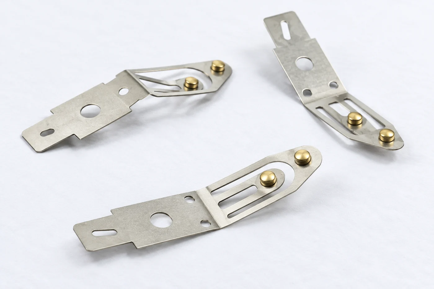
리벳 접점 조립품은 프레스로 만든 얇은 스프링 부품에 접점을 결합해 필요한 힘과 전기적 연결을 함께 만드는 구조입니다. 판스프링의 작은 비틀림이나 리베팅 중의 국부 변형은 접점 높이와 접촉력을 바꾸고, 그 변화는 저항·마모·신호 안정성으로 이어집니다. 따라서 프레스품과 접점을 각각 합격시키는 데서 끝내지 않고 실제 작동 상태의 완성 조립품으로 검증해야 합니다.
와이퍼 브러시형 부품의 설계에서는 슬릿과 분할 팔, 접점의 고정 계면, 상대면을 누르는 힘과 이동 궤적이 연결됩니다. 소재·성형·리베팅·표면처리부터 기계·전기·내구 검사까지 이 연결 관계를 기준으로 제작 조건을 정하면 초기 도통 이후의 품질까지 관리할 수 있습니다.
프레스와 접점의 기능 분담
판스프링·리벳 고정부·상대 접촉면의 힘과 전류 경로를 구분합니다.
성형과 리베팅의 연결
슬릿·조질·버·받침·성형 곡선을 조립 후 형상과 작동력에 연결합니다.
작동 성능과 양산 검증
와이핑·마모·저항·수명과 도면·검사·공급 조건을 정리합니다.
01조립 구조와 기능 경로
리벳 접점 조립품의 구조와 역할
리벳 접점 조립품은 얇은 프레스 부품과 작은 접점을 결합해 탄성·통전·접촉 기능을 나누어 맡기는 구조입니다. 판재는 위치를 잡고 필요한 힘을 만들며 전류를 전달합니다. 접점은 상대 부품과 직접 맞닿는 면의 전기적·마찰적 요구를 담당하고, 리벳 성형부는 두 부품의 결합 상태를 유지합니다.
접점을 단단히 붙였다는 사실만으로 조립품의 기능이 완성되지는 않습니다. 프레스 후 팔이 비틀리면 접점이 한쪽부터 닿고, 리베팅 중 판재가 눌리면 접점 높이와 작동 변위가 달라집니다. 외관상 작은 차이가 최종 접촉력과 신호 안정성으로 이어지므로 단품 치수와 조립 후 기능을 함께 관리해야 합니다.
와이퍼 브러시와 개폐 접점
현장에서 와이퍼 브러시라고 부르는 부품은 보통 탄성 접촉자가 상대 도전면을 따라 움직이며 접촉을 유지하는 용도와 연결됩니다. 그러나 비슷한 판스프링·원형 접점 구조라도 맞닿았다 떨어지는 개폐용 접점일 수 있습니다. 와이핑은 접촉 상태의 상대 미끄럼, 개폐는 회로를 연결하고 끊는 동작이며 한 제품에 두 동작이 함께 들어가기도 합니다.
| 작동 방식 | 핵심 기능 | 우선 검증 |
|---|---|---|
| 접촉 유지형 | 눌린 상태에서 전류·신호 전달 | 접촉력 유지·계면 저항·온도상승 |
| 와이핑·슬라이딩형 | 상대 도전면을 이동하며 접촉 유지 | 이동 중 저항·마모·미끄럼 저항 |
| 개폐형 | 정해진 위치에서 회로 연결·차단 | 작동 위치·바운스·부하 개폐 내구 |
프레스품과 접점의 기능 분담
설계의 출발점은 완성품의 작동도입니다. 고정되는 영역, 휘어지는 영역, 접점의 이동 궤적과 전류가 드나드는 지점을 표시하면 소재와 공정에서 무엇을 보호해야 하는지 분명해집니다. 같은 원형 접점을 사용해도 팔의 길이·접점 위치·상대면 형상에 따라 요구되는 제작 조건은 달라집니다.
사진형 일러스트와 회전 가능한 3D는 이 기능 관계를 설명하기 위한 형상 예시입니다. 특정 고객품의 도면·합금·정격이나 실제 검사 결과를 나타내지 않습니다. 중요한 비교 기준은 제품의 색이나 외형 유사성이 아니라 실제 조립 상태에서의 힘·이동·전류 경로입니다.
접촉력과 전류 경로
상대면이 접점을 누르면 힘은 접점 머리에서 판스프링을 거쳐 고정부로 전달됩니다. 반대로 전류는 단자 연결부와 판재, 리벳 고정부, 접점 몸체와 상대 접촉면을 차례로 지날 수 있습니다. 힘이 지나가는 경로와 전류가 지나가는 경로를 따로 그려야 얇은 목 부분의 휨과 발열을 놓치지 않습니다.
서로 다른 두 접촉 계면
리벳과 판재 사이의 고정 계면은 조립 이후 움직이지 않도록 유지해야 하는 곳입니다. 접점과 상대면 사이의 가동 계면은 접촉·분리 또는 미끄럼을 수행하는 곳입니다. 어느 한쪽의 저항이 증가해도 단자 사이에서 측정한 전체 저항은 커질 수 있으므로 측정 위치를 지정하지 않은 저항값으로 원인을 단정하기 어렵습니다.
| 구간 | 변화 요인 | 분리 확인 방법 |
|---|---|---|
| 판재·접점 몸체 | 재질·단면·경로 길이·온도 | 도면과 재질 확인, 정해진 구간의 전압강하 |
| 리벳 고정 계면 | 착좌·국부 압착·오염·풀림 | 조립부 주변 전압강하와 단면·고정력 대조 |
| 상대 접촉 계면 | 접촉력·피막·마모·상대 운동 | 실제 상대재와 작동 위치에서 저항·순간 단절 기록 |
통전 중 발생하는 전기적 발열은 단순한 정상 전류 조건에서 P = I²R로 비교할 수 있습니다. 여기서 R은 관심 구간의 저항이며 전체 부품의 모든 열 거동을 뜻하지 않습니다. 같은 전류에서 특정 리벳 주변만 뜨거워진다면 국부 저항, 전류가 좁아지는 단면과 방열 조건을 함께 확인하는 것이 합리적입니다.
접촉력과 실접촉 면적
매끈해 보이는 두 금속면도 미세한 돌기에서 먼저 맞닿습니다. 접촉력을 높이면 실제 전류 통로가 늘고 일부 표면막의 영향이 줄어들 수 있지만, 접점 머리의 겉보기 면적 전체가 균일하게 통전하는 것은 아닙니다. 따라서 접점 지름만 키우거나 힘만 높이는 변경은 표면 재료와 상대면의 변형을 함께 검토해야 합니다.
높은 초기 힘은 마찰과 구동 하중을 늘리고 얇은 팔의 응력 여유를 줄일 수도 있습니다. 설계 목표는 가능한 최대 힘이 아니라 최소 조립 눌림에서도 필요한 접촉을 얻고, 최대 눌림에서는 손상을 피하는 작동 범위입니다. 그 범위가 사용 온도와 시간 이후에도 유지되는지까지 확인해야 합니다.
02소재와 스프링 형상
판스프링 소재·조질·압연 방향
접점 조립품의 판재는 전도성만으로 선택하지 않습니다. 필요한 탄성 변위, 굽힘 가공성, 반복 수명과 온도에서의 힘 유지 능력을 함께 비교합니다. 인청동·황동·석출강화 동합금 등은 후보 재료군이며, 같은 이름 안에서도 합금 등급과 조질에 따라 성형성과 사용 가능한 응력 범위가 달라집니다.
강도·강성·응력완화의 구분
강도는 영구 변형에 대한 여유와 연결되고 강성은 같은 변위에 필요한 힘과 연결됩니다. 강성이 부족한 부품에 단지 더 강한 조질을 적용해도 원하는 힘이 바로 생기지는 않습니다. 반대로 이미 영구 변형이 발생하는 팔에서는 강도·형상·최대 변위를 함께 바꾸어야 복귀 성능을 회복할 수 있습니다.
| 재료 특성 | 제품에서 나타나는 의미 | 입고·개발 확인 |
|---|---|---|
| 탄성계수 | 형상이 같을 때의 초기 강성 | 설계에 사용한 물성과 실제 재질 일치 |
| 내력·조질 | 성형 후 영구 변형의 여유 | 재료 성적서·공급 상태·후속 열 이력 |
| 전도도 | 판재 내부의 저항과 발열 | 통전 경로·유효 단면·완성품 온도 |
| 응력완화 저항 | 눌린 상태에서의 장기 힘 유지 | 온도·시간·초기 변위가 같은 비교 시험 |
성형 후 시효가 필요한 재료와 공급 단계에서 경화된 재료는 제조 순서가 다릅니다. 필요한 열처리를 접점 조립이나 도금 뒤에 배치하면 형상·표면·접합부에 미치는 영향을 추가로 검증해야 합니다. 재료 선정 시점에 성형·열처리·리베팅·표면처리의 가능한 순서를 함께 검토하면 공정 간 충돌을 줄일 수 있습니다.
방향성과 얇은 팔의 변동
굽힘선과 압연 방향의 관계는 균열 여유에 영향을 줄 수 있습니다. 공급사의 굽힘 반경 자료를 사용할 때에는 두께·폭·조질·시험 방향이 실제 조건과 맞는지 확인합니다. 작은 시험편에서 통과한 반경이 슬릿 끝이나 접점 홀 옆에서도 같은 결과를 보장하는 것은 아닙니다.
얇은 판스프링에서는 두께 편차와 초기 휨이 접촉력 분포에 직접 들어갑니다. 코일 로트와 압연 방향을 공정 기록에 연결하고, 시제품과 양산품의 자유 높이뿐 아니라 같은 작동 위치에서의 힘을 비교해야 합니다. 여러 소재의 우열은 동일한 형상·조립 조건에서 요구 기능을 만족하는지로 판단합니다.
슬릿·분할 팔·접점 위치
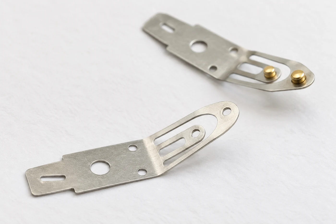
프레스 부품의 길쭉한 빈 공간은 단순 경량화 구멍이 아닐 수 있습니다. 슬릿은 휘어지는 팔의 폭과 길이, 서로 움직일 수 있는 방향을 정합니다. 접점 위치까지의 유효 스프링 경로가 바뀌면 전체 외곽 치수가 같아도 접촉력과 비틀림 거동은 달라집니다.
분할 팔의 힘 배분
두 팔에 접점이 하나씩 있어도 두 접점의 힘이 항상 같지는 않습니다. 자유 높이·팔 폭·접점 돌출 높이·상대면 기울기가 다르면 한쪽이 먼저 닿고 다른 쪽의 유효 눌림량은 작아집니다. 총 반력이 합격이어도 한 접점이 거의 힘을 받지 않을 수 있으므로 접점별 접촉 시작 위치와 힘 분포가 필요한 검사 항목입니다.
| 형상 요소 | 작동에 미치는 영향 | 설계 결정 |
|---|---|---|
| 슬릿 길이·팔 폭 | 탄성 경로·국부 강성·전류 단면 | 힘과 전도 요구를 함께 충족하는 폭·길이 |
| 슬릿 끝·급격한 폭 변화 | 응력 집중·균열 시작 위치 | 끝단 반경과 전이 형상·절단면 관리 |
| 접점의 좌우 위치 | 휨과 비틀림의 조합 | 하중 중심·상대 궤적·좌면 여유 |
| 공통 고정부 | 두 팔의 기계적·전기적 연결 | 고정 면적·기준 위치·회로 연결 확인 |
슬릿으로 나뉜 팔은 움직임이 분리될 수 있어도 같은 금속 뿌리로 이어져 있으면 전기적으로 연결되어 있습니다. 두 접점을 서로 다른 회로로 쓰려면 절연 구조와 전기적 분리를 별도로 설계해야 합니다. 단지 접점이 두 개라는 이유로 두 독립 채널이나 이중 안전 기능을 의미하지는 않습니다.
기준면에서 접촉점까지의 치수 경로
접점 위치는 외곽 기준만으로 관리하기보다 실제 장착 기준에서 정하는 편이 유효합니다. 고정 홀의 위치, 성형 높이, 접점 머리 높이와 상대 부품 위치가 합쳐져 작동 눌림량을 만듭니다. 치수 공차의 양 끝에서 두 팔이 모두 접촉하는지, 한쪽만 과도하게 눌리지 않는지 확인합니다.
구조 3D는 공통 고정부에 이어진 바깥 U형 탄성부와 안쪽 탄성 혀, 각 접점의 머리·샹크·고정 위치를 분리해 보여 줍니다. 바깥 탄성부는 양옆의 두 연결부가 하나의 접점 좌면으로 이어지고, 짧은 안쪽 탄성 혀에는 다른 접점이 놓입니다. 분해 상태에서 부품 관계를 확인하고 안착 상태에서 힘과 전류가 이어지는 경로를 비교할 수 있습니다. 이 형상은 구조 설명용이며 특정 제품의 전개도나 정량 해석 모델은 아닙니다.
긴 외곽 U와 짧은 중앙 텅의 접점 조립
INTERACTIVE 3D뒷면의 성형된 꼬리가 캐리어를 붙잡는 구조입니다. 단면 보기는 접점만 잘라 표시하며 캐리어는 유지합니다. 실제 홀·샹크·성형 치수는 도면과 공정 검증으로 정합니다.
03프레스 공정과 접점 구조
프레스 공정과 절단면 품질
프레스 접점 조립품은 타발·슬릿 가공·성형·접점 결합을 어떤 순서로 배치하는지가 중요합니다. 순송 공정에서는 캐리어와 파일럿이 위치를 유지하는 동안 필요한 구멍과 형상을 만들고, 접점 투입과 성형 후 분리 시점을 정합니다. 공정이 진행되는 동안 얇은 팔이 어디에 지지되는지도 함께 설계해야 합니다.
별도 조립과 금형 내 결합
프레스품을 개별로 만든 뒤 리베팅하면 공정 조정과 검사 접근이 쉽지만, 작은 부품을 다시 정렬하고 운반해야 합니다. 금형 내 또는 연속 스트립 상태에서 접점을 결합하면 재취급을 줄일 수 있으나 공급 누락·방향·스트립 변형이 연속 생산에 영향을 줍니다. 수량뿐 아니라 접점 종류, 형상 변경 가능성과 검사 위치를 기준으로 공정을 비교합니다.
| 공정 구간 | 발생 가능한 변화 | 관리 방법 |
|---|---|---|
| 타발·슬릿 | 버·절단면 손상·팔 폭 편차 | 금형 간극·날 상태·슬러그 배출과 치수 확인 |
| 굽힘·성형 | 자유 높이·비틀림·스프링백 | 소재 방향·지지·성형 위치와 복귀 형상 비교 |
| 접점 투입 | 누락·반전·기울어진 삽입 | 접점 유무·방향·샹크 통과 상태 확인 |
| 최종 분리 | 캐리어 해방에 따른 변형 | 분리 전후 형상·접점 위치·작동력 대조 |
버는 접점 좌면의 들뜸, 상대면 긁힘과 금속 이물의 원인이 될 수 있습니다. 다만 버 높이만 낮다고 절단면 내부의 손상이나 슬릿 끝 균열 여유까지 좋다고 판단할 수는 없습니다. 기능상 민감한 가장자리를 지정하고 확대 관찰·단면·후속 성형 결과를 함께 비교해야 금형 간극과 보수 시점을 정할 수 있습니다.
조립 공정 이후의 형상 확인
성형을 먼저 하면 접점 머리가 후속 금형과 부딪힐 위험을 줄일 수 있지만, 굽혀진 팔을 리베팅 장치에서 받치기 어려울 수 있습니다. 접점을 먼저 붙이면 평판 상태의 지지는 쉬워져도 후속 성형에서 접점 기울기와 표면 손상을 관리해야 합니다. 어느 순서든 마지막 공정 뒤의 자유 높이와 접점 위치가 최종 판정의 기준입니다.
레이저 절단이나 단순 지그로 만든 시제품은 조립 개념을 확인하는 데 유용합니다. 그러나 양산 타발의 절단면·버 방향·캐리어 구속과 다르면 피로와 접촉력 결과도 달라질 수 있습니다. 최종 승인 단계에서는 양산에 가까운 소재·절단·성형·리베팅 조건의 시료로 민감한 기능을 다시 확인합니다.
접점 재료와 리벳 구조
판스프링 재료와 접점 표면 재료는 서로 다른 기준으로 선택합니다. 스프링은 필요한 변위와 전류 경로를 담당하고, 접촉면은 표면막·마모·미세 신호 또는 개폐 부하에 대응합니다. 금빛·은빛 외관은 합금 조성이나 도금 두께를 증명하지 않으므로 재질과 표면 요구는 도면·성적서로 연결합니다.
통전 조건과 표면 재료의 조합
미소 신호 접점은 작은 전압·전류에서 표면막의 영향을 줄이는 것이 중요합니다. 전류를 끊는 개폐 접점은 아크·용착·재료 전이까지 검토해야 하며, 슬라이딩 접점은 상대재와 마모가루의 거동이 추가됩니다. 하나의 재료를 모든 용도에 우수하다고 정하기보다 전압·전류·부하 종류·운동·환경을 묶어 비교합니다.
| 구조 | 재료 배치의 의미 | 주의할 구분 |
|---|---|---|
| 단일 재료 접점 | 몸체와 접촉부를 같은 재료로 구성 | 성형성·표면 성능·재료 사용량의 균형 |
| 복합 리벳 접점 | 접촉부와 샹크에 다른 재료 사용 가능 | 복합재 내부 접합과 판재 리베팅은 별도 계면 |
| 선택 도금 접점 | 필요한 표면에 기능층 배치 | 위치·두께·하부층·성형 후 상태 관리 |
| 용접용 접점·클래드 판재 | 다른 접합·소재 경로로 접촉 기능 확보 | 리벳 샹크 구조와 동일하게 취급하지 않음 |
리벳 머리는 상대면과 접촉하는 형상을, 샹크는 판재 홀을 통과해 고정되는 형상을 갖습니다. 돌출 길이가 부족하면 충분한 고정 형상을 만들기 어렵고 지나치면 불필요한 성형량과 주변 간섭이 늘어날 수 있습니다. 머리·샹크·홀·판 두께는 독립 치수가 아니라 하나의 조립 조합으로 검토해야 합니다.
접촉면 형상과 고정 형상의 분리
머리가 평평한지 완만하게 볼록한지에 따라 상대면에 처음 닿는 위치와 접촉 흔적이 달라집니다. 이 형상은 조립 중 생긴 눌림 자국이나 긁힘과 구분해 관리해야 합니다. 접촉면이 손상되면 고정력은 합격이어도 작동 저항과 마모 거동이 바뀔 수 있습니다.
샹크는 고형·중공 등 설계에 따라 성형 방식이 달라질 수 있습니다. 리벳 단면 3D에서는 원리를 명확하게 보여 주기 위해 고형 샹크의 꼬리를 눌러 넓히는 예시를 사용합니다. 다른 단면의 리벳에 동일한 공구 형상이나 성형량을 그대로 적용하는 의미는 아닙니다.
04리베팅과 작동력
리베팅 받침과 성형 공정
리베팅은 샹크 끝을 넓히는 동안 접점과 판재를 올바른 위치에 유지하는 작업입니다. 먼저 접점 머리를 형상에 맞는 받침에 안착시키고 판재 홀과 샹크를 정렬합니다. 공구가 꼬리를 성형할 때 힘이 얇은 스프링 팔 전체의 휨으로 빠지지 않도록, 결합 부위 주변의 지지와 공구 접근을 함께 확보합니다.
착좌·돌출·고정 형상의 연결
홀 주변의 버나 이물이 끼면 머리가 기울어진 상태에서 꼬리가 성형될 수 있습니다. 반대로 과도한 가압은 판재를 움푹 누르거나 접점 머리까지 변형시켜 자유 높이를 바꿀 수 있습니다. 완성 꼬리의 폭만 보는 대신 머리의 밀착·축 기울기·판재 국부 변형과 해방 후 형상을 함께 확인해야 합니다.
| 관찰 결과 | 확인할 원인 | 판정에 연결할 측정 |
|---|---|---|
| 접점 들뜸·회전 | 착좌 불량·성형 부족·구멍 상태 | 머리 아래 틈·유지력·계면 전압강하 |
| 판재 휨·자유 높이 변화 | 국부 받침 부족·과도한 변위 | 성형 전후 형상·접점별 작동력 |
| 꼬리 균열·비대칭 | 정렬·재료 상태·돌출과 공구 형상 | 확대 관찰·절단면·고정 성능 |
| 가압 곡선 변화 | 부품 누락·두께·돌출·마찰·금형 상태 | 하중–변위 기록과 양품/불량 실물 대조 |
성형 방식은 직선 가압, 회전·요동 계열 등 장비와 부품에 따라 달라집니다. 방식의 이름보다 중요한 것은 접촉면을 보호하면서 목표 고정 형상을 반복할 수 있는지입니다. 마찰과 공구 운동이 다르면 같은 최대 하중에서도 형상과 표면 결과가 달라지므로 조건은 공정별로 정해야 합니다.
하중–변위 곡선과 실물 검증
하중–변위 기록에서는 공구가 처음 닿는 위치, 성형 구간의 기울기, 종료 위치와 최대 하중을 함께 봅니다. 최댓값 하나가 같아도 중간에 부품이 미끄러지거나 받침이 변형되는 과정은 다를 수 있습니다. 다만 곡선 이탈만으로 불량 원인을 확정하거나 정상 곡선만으로 내부 결합 상태를 보증할 수는 없습니다.
개발 단계에서는 성형 조건을 바꾼 시료의 단면·고정력·전기 저항과 곡선을 연결해 허용 구간을 설정합니다. 양산 중에는 공구 보수와 소재 로트 변경 후에도 이 관계가 유지되는지 확인합니다. 리벳 단면 3D는 받침 위에 안착한 머리와 판재를 유지하며 꼬리가 넓어지는 과정을 보여 주고, 실제 성형 하중이나 잔류 응력 계산을 대신하지 않습니다.
헤드를 받치고 샹크 꼬리를 성형하는 리벳팅
INTERACTIVE 3D공구가 후퇴한 뒤 넓어진 꼬리가 캐리어 뒷면에 걸립니다. 헤드와 꼬리의 좌면, 흔들림·회전, 균열과 전기적 성능은 실제 검사·시험으로 판정합니다.
작동 변위·접촉력·과행정
자유 높이가 맞아도 사용 위치에서의 접촉력이 같다는 뜻은 아닙니다. 고정부가 실제로 어디까지 구속하는지, 접점이 상대면에 언제 닿는지, 닿은 뒤 얼마나 더 눌리는지가 힘을 정합니다. 조립품 검사는 자유 상태의 치수와 실제 고정 조건에서의 힘–변위 특성을 연결해야 합니다.
단순 스프링 모델의 민감도
직선·일정 폭·직사각 단면의 외팔보가 끝에서 수직 힘을 받고 작게 휜다는 가정에서는 F ≈ Ebt³δ / (4L³)입니다. E는 탄성계수, b는 폭, t는 두께, L은 유효 길이, δ는 탄성 눌림량입니다. 같은 조건에서 두께를 5% 늘리면 힘은 약 15.8% 커지므로 작은 두께 변화도 힘 편차로 확대될 수 있습니다.
이 관계는 형상 민감도를 이해하는 비교식입니다. 곡선형 팔, 슬릿이 이어진 구조, 큰 회전과 마찰이 있는 실제 조립품에서는 그대로 정격을 계산할 수 없습니다. 실제 형상의 해석과 힘–변위 시험을 연결하고, 접촉 전 구간을 접촉력 발생 구간으로 잘못 계산하지 않아야 합니다.
| 작동 구간 | 확인할 기능 | 설계·검사 기준 |
|---|---|---|
| 접촉 전 | 충분한 간격·의도된 개방 | 초기 간격·간섭·접촉 시작 위치 |
| 최소 눌림 | 두 접점의 필요한 힘 확보 | 접점별 최소 힘·저항·단절 여부 |
| 정상 이동 | 접촉력 유지와 상대면 추종 | 힘 변화·미끄럼 저항·동적 저항 |
| 최대 눌림·복귀 | 과도 응력·영구 변형 억제 | 스토퍼 위치·최대 힘·복귀 후 잔류 변형 |
초기 힘과 사용 후 유지력
응력완화는 일정하게 눌린 상태에서 시간이 지나며 힘이 감소하는 현상입니다. 첫 과행정에서 생긴 영구 변형이나 반복 운동에 의한 피로와 원인이 다릅니다. 온도·유지 시간·초기 변위를 지정한 뒤 같은 작동 위치에서 힘을 다시 측정해야 변화량을 비교할 수 있습니다.
조립 공차의 최소 조건에서는 접촉이 끊어지지 않는지, 최대 조건에서는 팔과 접점에 손상이 남지 않는지 확인합니다. 구동부의 정지 위치만 관리하면 조립 오차가 스프링으로 전가될 수 있으므로 스토퍼와 기준면을 함께 정합니다. 공차 누적을 흡수할 변위 여유는 높은 초기 힘과 별도로 확보해야 합니다.
05마모·표면·청정도
와이핑·마모·프레팅
와이핑은 접촉면을 상대적으로 움직여 표면막이나 일부 오염의 영향을 줄이는 데 도움이 될 수 있습니다. 동시에 마찰로 기능층과 상대면을 마모시키므로 이동량을 크게 할수록 항상 유리한 것은 아닙니다. 접촉력·이동 거리·속도·반복 횟수와 상대 재료를 하나의 시험 조건으로 다루어야 합니다.
의도된 미끄럼과 미세 진동
프레팅은 진동이나 열팽창 차이 등으로 접촉부가 작은 범위에서 반복적으로 움직이는 현상과 연결됩니다. 마모가루가 접촉 영역에 남고 산화되면 저항이 커질 수 있습니다. 설계된 긴 이동 궤적에서의 마모 시험과 정지 위치의 미세 진동 시험은 목적이 다르므로 한 결과로 다른 조건의 수명을 대신하지 않습니다.
| 현상 | 원인 경로 | 확인할 결과 |
|---|---|---|
| 초기 저항 불안정 | 착좌·표면막·접촉력 변화 | 작동 위치별 저항과 접촉 흔적 |
| 반복 이동 후 열화 | 기능층 손실·상대면 마모 | 마모 깊이·노출층·이동 중 저항 |
| 정지 중 진동 열화 | 미세 미끄럼·가루 축적·산화 | 진동 중 단절·전후 저항·표면 분석 |
| 접점별 편마모 | 힘 불균형·기울기·궤적 차이 | 두 팔의 힘·마모 자국 위치·상대면 평탄성 |
도금 접촉자의 마모·프레팅 연구에서는 접촉부에 귀금속이 남아 있어도 산화된 마모가루가 그 위를 덮으면 전기적 기능이 나빠질 수 있음을 보여 줍니다. 따라서 반짝이는 면의 잔존 여부나 평균 마모량만으로 수명을 판정하지 않습니다. 마모 흔적·가루 분포와 동작 중 저항 변화를 함께 보면 열화 원인을 더 정확히 구분할 수 있습니다.
윤활과 접촉 경로의 검증
윤활은 마찰과 마모를 줄일 수 있지만 전기 접촉에 적합한 종류·도포량·온도 조건이 필요합니다. 일반 방청유나 잔류 프레스유를 기능성 접점 윤활로 간주해서는 안 됩니다. 적용할 경우 무윤활 기준과 비교하고 먼지 포집·재료 적합성·저온 구동력·장기 저항까지 검증 항목에 포함합니다.
동작 3D에서는 접촉 전과 눌린 상태, 상대면을 따라 이동하는 상태를 구분해 볼 수 있습니다. 두 팔이 각기 상대면을 따르는 모습은 분할 구조의 목적을 설명합니다. 실제 마찰계수·접촉저항·피로수명을 계산하는 장면은 아니며, 최종 평가는 정해진 상대재와 작동 궤적으로 수행합니다.
두 접점의 순응성과 접촉 와이핑
INTERACTIVE 3D상대 도체가 더 이동하면 두 가지가 처지며 접촉을 유지하는 개념입니다. 화살표는 누르는 방향만 나타내며 실제 힘·응력·수명이나 두 가지의 힘 비율을 계산하지 않습니다.
표면처리·세척·포장
접점 조립품의 표면 요구는 부위별로 달라집니다. 상대면과 맞닿는 영역, 판재의 리벳 좌면, 외부 연결부와 일반 노출면을 나누어 관리해야 합니다. 전면을 같은 방식으로 처리하는 것이 항상 유리한 것은 아니며 선택 처리의 경계가 실제 접촉 궤적과 어긋나지 않아야 합니다.
도금 순서와 기능면 보호
선도금 판재를 타발하면 절단면에는 원래 피막이 이어지지 않습니다. 반면 조립 후 도금은 노출된 면을 처리할 수 있어도 겹침부 내부까지 균일하게 처리된다고 볼 수 없습니다. 접점 자체의 기능층과 모재 방청층을 구분하고, 최종 변형·세척·검사 순서에 맞는 표면 요구를 정합니다.
| 관리 영역 | 품질 위험 | 실무 확인 |
|---|---|---|
| 접촉면 | 긁힘·압흔·기능층 손실 | 허용 결함 위치·범위·표면 상태 |
| 리벳 겹침부 | 가공유·세정액·수분 잔류 | 세정·헹굼·건조 후 잔류와 전기 특성 |
| 슬릿·절단면 | 금속 가루·버·처리 사각 | 확대 관찰과 기능상 민감한 이물 관리 |
| 운송·보관 | 팔 눌림·부품끼리의 긁힘·오염 | 지지 위치·분리 포장·보관 조건 |
세척은 외관을 밝게 만드는 과정이 아니라 기능을 방해하는 잔류물을 줄이는 과정입니다. 세정제와 건조 조건이 모재·도금·접점에 적합한지 확인하고, 검증된 기능성 윤활을 적용하는 경우에는 세척 순서를 충돌 없이 정합니다. 겹침부에 남은 액체가 보관 중 표면 변화를 일으키지 않도록 건조 결과도 확인해야 합니다.
검사 상태와 납품 상태의 일치
전기 검사를 통과한 뒤 맨손 취급이나 벌크 포장으로 오염·변형이 생기면 검사 결과의 의미가 줄어듭니다. 포장은 가동 팔을 눌러 두지 않고 고정부를 지지하며, 접점 머리끼리 반복해서 부딪히지 않도록 구성합니다. 최종 포장 전 형상과 표면을 확인하고 필요하면 포장·운송 모사 후 기능을 대조합니다.
재료 로트·프레스 설정·리베팅 조건·표면처리 배치를 연결해 두면 저항 변화나 힘 편차의 발생 범위를 좁힐 수 있습니다. 세척 전 검사품과 세척 후 납품품을 같은 상태로 취급하지 않도록 검사 시점도 기록합니다. 이력은 문서의 양보다 실제 품질 변화와 연결할 수 있는 구분 단위가 중요합니다.

06검증과 양산 승인
기계·전기·내구 검증
검사는 접점 고정, 스프링 작동, 전기적 연결을 서로 구분해 설계합니다. 밀어내기·회전·인장 등의 시험은 하중 방향과 지그가 정의되어야 의미가 있고, 큰 고정력 하나가 낮은 계면 저항까지 증명하지는 않습니다. 반대로 초기 도통이 된다고 리벳이 장기적으로 움직이지 않는다고 판단할 수도 없습니다.
측정 위치와 전기 시험 순서
낮은 저항은 보통 전류 인가선과 전압 검출선을 분리하는 4선식으로 측정합니다. 그러나 4선식도 검출점 사이에 들어 있는 판재·리벳·상대 접촉면의 저항을 자동으로 분리하지는 않습니다. 측정 지점, 상대재, 눌림 위치와 온도를 고정하고 프로브가 얇은 팔을 추가로 눌러 결과를 바꾸지 않도록 합니다.
미소 신호용 표면을 평가할 때 지나치게 높은 시험 전압이나 전류는 피막·접촉점을 변화시킬 수 있습니다. 밀리볼트 수준 접촉저항 시험은 이런 목적에 맞게 상세 조건을 정하며, IEC 60512-2-1은 커넥터 접촉저항의 밀리볼트 수준 측정을 다루는 방법으로 적용 범위를 검토할 수 있습니다. 이 방법을 참고하는 것과 리벳 조립품 전체의 적합성을 입증하는 것은 구분해야 합니다. 저수준 시험은 큰 전류의 시험보다 먼저 배치하고, 온도상승 시험과 합격 한계를 별도로 정합니다.
| 검증 항목 | 시험 조건의 핵심 | 얻을 수 있는 판단 |
|---|---|---|
| 형상·착좌 | 실제 기준면·최종 표면 상태 | 접점 위치·기울기·홀·국부 변형 |
| 힘–변위 | 고정 길이·가압점·속도·복귀 경로 | 최소 힘·최대 힘·잔류 변형 |
| 저항·동적 연속성 | 검출점·시험 전원·대역폭·작동 궤적 | 초기 저항·순간 단절·시간 변화 |
| 사용 후 성능 | 온도·진동·반복·실제 부하의 조합 | 힘 유지·마모·풀림·전기적 열화 |
수명 시험과 고장 기준
슬라이딩 중 잠깐 발생하는 단절은 시험 전후의 평균 저항만으로 놓칠 수 있습니다. 허용 단절 시간·저항 한계·측정 대역폭을 정하고, 반복 이동 또는 진동 중에 신호를 기록해야 합니다. 개폐용이라면 실제 부하 종류와 전압·전류에서 바운스·용착·소모를 추가로 평가합니다.
재료의 굽힘 피로시험과 완성 조립품의 내구시험은 같은 시험이 아닙니다. ASTM B593과 같은 재료 시험은 비교 자료를 제공하지만 실제 슬릿·접점 질량·고정·부식 환경을 모두 재현하지 않습니다. 시제품 검증에서는 실패 모드와 종료 기준을 먼저 정하고, 시험 후 단면·표면·힘·저항을 연결해 개선 대상을 찾습니다.
도면 사양과 양산 승인
리벳 접점 조립품의 도면에는 모재 외곽과 접점 지름 외에 실제 기능을 정하는 정보가 필요합니다. 장착 기준, 접점 위치와 높이, 작동 변위 구간, 접점별 힘과 표면 요구를 하나의 개정으로 연결합니다. 단품 도면만으로 설명하기 어려운 움직임은 조립도와 작동 상태도를 함께 제공하는 편이 명확합니다.
제작 의뢰의 필수 정보
| 전달 자료 | 구체적으로 정할 내용 | 연결되는 공정·판정 |
|---|---|---|
| 형상·재료 | 동일 개정 2D/3D·모재 조질·접점 구조 | 전개·성형·열처리·리벳 조합 |
| 작동·회로 | 고정 위치·상대재·이동·전압·전류·부하 | 접촉력·재료 선택·동적 시험 |
| 표면·품질 | 기능면·도금·청정도·허용 결함 | 처리 순서·검사·포장 |
| 승인·공급 | 수량·단품/스트립·시료·검사 자료·변경 관리 | 금형 구성·자동화·양산 승인 범위 |
양산 승인에는 평균값뿐 아니라 접점별 편차와 시간에 따른 변화를 포함합니다. 소재 로트·금형 보수·설정 변경에서 자유 높이, 작동력과 고정 상태가 어떻게 움직이는지 확인합니다. 측정 반복성부터 확보하고 공정이 안정된 뒤 공정능력을 평가해야, 작은 산포가 좋은 제조 능력인지 단지 시험 조건의 결과인지 구분할 수 있습니다.
변경 관리와 완성 조립품 비용
접점 재질·샹크 길이·도금·모재 조질을 바꾸면 구매 단가뿐 아니라 성형 조건과 작동 결과도 달라질 수 있습니다. 외형이 같다는 이유로 대체품을 바로 승인하지 않고 어떤 계면과 기능이 변하는지부터 검토합니다. 변경 영향에 따라 리베팅 단면·힘–변위·저항·내구 시험 중 필요한 항목을 다시 수행합니다.
원가는 접점 하나의 귀금속 사용량보다 넓게 비교해야 합니다. 금형과 공급 장치, 조립 재취급, 검사, 스크랩 회수와 재작업까지 포함하면 다른 공정이 더 유리해질 수 있습니다. 접촉부의 필요한 재료를 줄이는 변경은 마모 여유·상대 운동·도금 범위와 함께 검증해야 완성 양품의 비용 절감으로 이어집니다.
English Edition · Riveted Contact Assemblies: Stamped Springs, Wiper Brushes and Quality Control
Riveted contact assemblies attach contact elements to thin stamped springs to provide both force and electrical connection. Small spring distortions or local deformation during riveting change contact height and force, affecting resistance, wear and signal stability. Acceptance of the stamping and contact as separate parts must therefore be followed by validation of the complete assembly in its operating condition.
In a wiper-brush arrangement, slots and divided arms interact with the fixed rivet interface, normal force and contact trajectory. Connecting material selection, forming, riveting and finishing to mechanical, electrical and endurance inspection allows manufacturing conditions to address quality beyond initial continuity.
Functions within the assembly
Separate force and current paths through the spring, riveted joint and mating interface.
Forming and riveting together
Connect slots, temper, burrs, support and forming traces to final geometry and operating force.
Operation and production validation
Relate wiping, wear, resistance and life to drawings, inspection and supply conditions.
01Assembly structure and functional paths
Structure and function of riveted contact assemblies
Riveted contact assemblies combine a thin stamping with a small contact element so that compliance, conduction and surface contact can be addressed separately. The sheet locates the assembly, generates the required force and carries current. The contact element serves the electrical and frictional requirements of the mating surface, while the formed rivet tail retains the connection.
Secure attachment alone does not establish the function of the assembly. Twist introduced during stamping can make one edge touch first; distortion during riveting changes contact height and operating deflection. Small visible differences can therefore affect final contact force and signal stability, requiring control of both individual dimensions and assembled function.
Wiper brushes and switching contacts
The term wiper brush generally refers to a compliant contact that maintains electrical contact while moving along a conductive surface. A similar leaf-spring and round-contact arrangement can also serve a make-and-break function. Wiping is relative sliding while the surfaces remain in contact; switching makes or breaks the circuit, and a product may combine both motions.
| Operating mode | Main function | Priority validation |
|---|---|---|
| Maintained contact | Carry current or signals under sustained engagement | Force retention, interface resistance and temperature rise |
| Wiping or sliding | Maintain contact while moving over a conductive surface | Resistance during motion, wear and sliding resistance |
| Make-and-break | Connect and interrupt a circuit at defined positions | Operating position, bounce and loaded switching endurance |
Functional division between stamping and contact
Start with the operating arrangement of the finished device. Mark the fixed region, flexible region, contact trajectory and electrical entry and exit points to identify what material selection and processing must preserve. Even with the same round contact, arm length, contact location and mating geometry lead to different manufacturing requirements.
The photographic illustrations and interactive 3D models provide geometric examples of these functional relationships. They do not state a customer drawing, alloy, rating or measured inspection result. The useful basis for comparison is the force, motion and current path in the assembled condition rather than color or visual resemblance.
Contact force and current paths
When the mating surface presses the contact, force travels from the contact head through the spring to the fixed region. Current may pass through the terminal connection, sheet, riveted interface, contact body and mating interface in sequence. Drawing the mechanical and electrical paths separately helps identify a narrow neck that affects both bending and heating.
Two distinct contact interfaces
The fixed interface between rivet and sheet should remain stable after assembly. The moving interface between the contact and its counterpart performs engagement, separation or sliding. Increasing resistance at either interface can raise the terminal-to-terminal result, so a resistance value without defined sensing locations cannot identify the cause.
| Region | Sources of variation | Ways to separate the effect |
|---|---|---|
| Sheet and contact body | Material, section, path length and temperature | Material/drawing checks and voltage drop across a defined region |
| Riveted interface | Seating, local compression, contamination and loosening | Local voltage drop compared with sections and retention tests |
| Mating interface | Normal force, films, wear and relative motion | Resistance and interruptions with the actual counterpart at operating positions |
Under a simple steady-current condition, electrical heating can be compared using P = I²R. Here R is the resistance of the region of interest, not a complete thermal model of the assembly. If one riveted region becomes hotter at the same current, examine its local resistance, restricted current-carrying section and heat-transfer conditions together.
Normal force and real contact area
Even apparently smooth metal surfaces first touch at microscopic high points. Increasing normal force can enlarge conducting paths and reduce the influence of some surface films, but current does not flow uniformly over the entire apparent head area. Increasing diameter or force therefore requires consideration of the surface materials and deformation of the counterpart.
A higher initial force can also increase friction and actuation load while reducing the stress margin of a thin arm. The objective is an operating window that maintains adequate engagement at minimum assembly deflection and avoids damage at maximum deflection. That window must remain adequate after the specified temperature exposure and time in service.
02Materials and spring geometry
Spring material, temper and rolling direction
Select the sheet for more than conductivity. Compare elastic travel, formability, cyclic life and force retention at temperature. Phosphor bronzes, brasses and precipitation-strengthened copper alloys are candidate families; grade and temper within each family affect formability and the usable stress range.
Strength, stiffness and stress relaxation
Strength relates to the margin against permanent deformation, whereas stiffness relates to the force required for a given deflection. A stronger temper alone does not necessarily provide the desired force in an otherwise elastic part. If the arm already takes a permanent set, strength, geometry and maximum deflection must be considered together to restore recovery.
| Material property | Meaning in the product | Incoming and development checks |
|---|---|---|
| Elastic modulus | Initial stiffness for a given geometry | Agreement between design data and supplied material |
| Proof strength and temper | Margin against permanent set after forming | Certificate, delivery condition and subsequent thermal history |
| Conductivity | Bulk resistance and heating in the sheet | Current path, effective section and assembled temperature |
| Stress-relaxation resistance | Long-term force retention under held deflection | Comparisons at equal temperature, time and initial deflection |
A material requiring aging after forming follows a different process route from one supplied in a hardened condition. Placing a required heat treatment after contact assembly or plating introduces additional questions about geometry, surfaces and the joint. Reviewing forming, heat treatment, riveting and finishing together during material selection reduces conflicts between operations.
Directionality and variation in thin arms
The relationship between bend line and rolling direction can affect cracking margin. Supplier bend-radius data should match thickness, width, temper and test orientation. A radius that passes on a simple test strip does not automatically give the same result near a slot termination or contact hole.
Thickness variation and initial curvature directly influence force distribution in a thin spring. Link coil identity and rolling direction to process records, and compare prototypes with production parts by force at the same operating position as well as free height. Material comparisons should be based on meeting the functional requirement under equivalent geometry and assembly conditions.
Slots, divided arms and contact position
An elongated opening in a stamping may do much more than reduce weight. Slots define the width, length and permitted movement of flexible arms. Changing the effective spring path to the contact can alter normal force and twisting behavior even when the overall outline remains unchanged.
Force sharing between divided arms
Two arms carrying one contact each do not necessarily develop equal forces. Differences in free height, arm width, contact protrusion or mating-surface tilt can make one contact engage first and leave less effective deflection at the other. A passing total reaction force can conceal a nearly unloaded contact, making individual engagement positions and force distribution useful inspection targets.
| Geometric feature | Operating effect | Design decision |
|---|---|---|
| Slot length and arm width | Flexible path, local stiffness and conducting section | Width and length satisfying both force and conduction needs |
| Slot termination and abrupt width change | Stress concentration and crack initiation | End radius, transition profile and cut-edge control |
| Lateral contact position | Combined bending and twisting | Load center, mating trajectory and seating margin |
| Shared fixed region | Mechanical and electrical coupling between arms | Clamped area, datum position and circuit connection |
Slotted arms can move separately while remaining electrically connected through a common metal root. Separate circuits require an explicitly designed insulating arrangement and electrical separation. Two contact buttons alone therefore do not imply independent channels or a redundant safety function.
Dimensions from the datum to the contact point
It is useful to locate contacts from the actual mounting datums rather than only from the external outline. Mounting-hole position, formed height, contact-head height and counterpart position combine to determine operating deflection. Check the tolerance extremes for engagement of both arms and excessive deflection of either one.
The structural 3D model separates the outer U-shaped spring, the shorter inner tongue connected to the same fixed region, and the head, shank and attachment position of each contact. The two side rails of the outer spring join at one contact land, while the inner tongue carries the other contact. The exploded state shows component relationships, while the seated state supports comparison of force and current paths. This geometry illustrates the structure rather than the flat pattern or quantitative analysis model of a specific product.
Contact assembly on an outer U and inner tongue
INTERACTIVE 3DThe formed tails retain the carrier from the rear. Section view cuts only the contacts and leaves the carrier intact. Actual hole, shank and upset dimensions require drawings and process validation.
03Stamping and contact construction
Press operations and cut-edge quality
The order of blanking, slotting, forming and contact attachment matters in a pressed contact assembly. In a progressive route, the carrier strip and pilots preserve position while holes and shapes are produced, and contact insertion must be coordinated with forming and final separation. Tooling must also define how the thin arms are supported throughout the sequence.
Separate assembly and in-die attachment
Riveting individual stampings can simplify process adjustment and inspection access, but requires reorientation and handling of small parts. Attaching contacts in the die or while parts remain on a continuous strip can reduce handling, while making feed omissions, orientation and strip distortion important to continuous production. Compare routes by contact type, expected design changes and inspection access as well as volume.
| Process stage | Possible change | Control approach |
|---|---|---|
| Blanking and slotting | Burrs, edge damage and arm-width variation | Die clearance, cutting edges, slug removal and dimension checks |
| Bending and forming | Free height, twist and springback | Compare stock direction, support, forming position and released shape |
| Contact insertion | Missing, inverted or tilted contacts | Check presence, orientation and shank passage |
| Final separation | Distortion as the carrier constraint is removed | Compare shape, contact position and operating force before/after separation |
Burrs can lift a contact seat, scratch a counterpart or become metallic debris. A low burr height does not by itself establish low subsurface edge damage or adequate crack margin at a slot end. Identify functionally sensitive edges and compare magnified inspection, sections and subsequent forming behavior when setting clearance and maintenance intervals.
Shape checks after assembly operations
Forming first can avoid exposing contact heads to subsequent forming tools, but may make a bent arm harder to support during riveting. Attaching contacts first can simplify support of a flat blank while requiring protection against tilt and surface damage during later forming. In either sequence, final free height and contact position must be assessed after the last operation.
Laser-cut prototypes and simple fixtures are useful for establishing the assembly concept. Differences from production in cut edges, burr direction or carrier restraint can nevertheless affect fatigue and contact force. Final approval should therefore revisit sensitive functions using samples with material, cutting, forming and riveting conditions representative of production.
Contact materials and rivet construction
The spring material and contact surface require different selection criteria. The spring provides travel and a conducting path; the contact surface addresses films, wear, low-level signals or switching loads. Gold or silver appearance does not establish alloy composition or coating thickness, so material and surface requirements belong in drawings and certification records.
Electrical duty and surface material
Low-level signal contacts must manage surface films under small voltages and currents. Switching contacts additionally require consideration of arcing, welding and material transfer, while sliding contacts introduce counterpart wear and debris behavior. Compare a material against the combined voltage, current, load type, motion and environment instead of treating it as superior for every duty.
| Construction | Purpose of material placement | Important distinction |
|---|---|---|
| Solid single-material contact | One material forms body and contact region | Balance formability, surface performance and material usage |
| Composite contact rivet | Contact region and shank can use different materials | The internal composite bond differs from the rivet-to-sheet interface |
| Selectively plated contact | Place a functional layer on the required surface | Control location, thickness, underlayer and post-forming condition |
| Welded contacts or clad strip | Provide contact function through another joining/material route | Do not treat these as the same shank-based rivet construction |
The head provides the mating geometry, while the shank passes through the sheet hole and is formed to retain it. Insufficient projection can prevent formation of an adequate retaining shape; excess projection can increase deformation demand and interference. Head, shank, hole and sheet thickness therefore form one assembly combination rather than independent dimensions.
Mating geometry and retaining geometry
A flat or gently crowned head changes initial contact position and the resulting wear mark. Distinguish this intended geometry from dents or scratches introduced during assembly. A damaged active face can change operating resistance and wear even when mechanical retention passes.
Shanks may be solid or hollow, with different forming requirements. The riveting cutaway uses a solid shank whose tail is upset outward to make the principle visible. It does not imply that the same tool profile or forming displacement applies to another shank construction.
04Riveting and operating force
Riveting support and forming control
Riveting must hold the contact and sheet in the correct position while enlarging the end of the shank. Seat the contact head in a support suited to its profile, then align the sheet hole and shank. Provide local support and tool access so that tail-forming force does not mainly bend the thin spring arm.
Seating, projection and retaining shape
A burr or particle around the hole can leave the head tilted when the tail is formed. Excessive loading can indent the sheet or deform the active head, changing free height. Inspect head seating, axis tilt, local sheet distortion and released geometry together rather than judging only the final tail width.
| Observation | Causes to investigate | Measurements supporting disposition |
|---|---|---|
| Head lift or rotation | Poor seating, insufficient forming or hole condition | Under-head gap, retention and interface voltage drop |
| Sheet bending or changed free height | Inadequate local support or excess displacement | Geometry before/after forming and individual operating forces |
| Cracked or asymmetric tail | Alignment, material condition, projection or tool profile | Magnified inspection, sections and retention performance |
| Changed forming curve | Missing part, thickness, projection, friction or tool condition | Force–displacement trace compared with physical conforming/nonconforming samples |
Forming may use axial pressing or rotational/orbital methods depending on equipment and part design. More important than the process name is whether it repeatedly produces the required retention geometry while protecting the active surface. Different friction and tool motion can produce different shapes and surfaces at the same peak load, so settings must be process-specific.
Force–displacement traces and physical validation
A force–displacement trace includes first contact, the slope of the forming region, final position and peak force. Equal peaks can hide different intermediate events such as slipping or support deflection. A trace deviation does not uniquely identify a defect, and a normal trace alone cannot certify the internal joint condition.
During development, establish an acceptable process window by relating traces to sections, retention and electrical resistance on samples made at varied settings. Verify that this relationship remains valid after tool maintenance or material-lot changes. The cutaway model shows the head and sheet supported while the tail expands; it is not a calculation of forming force or residual stress.
Support the head and upset the shank tail
INTERACTIVE 3DAfter tool retraction, the wider tail retains the rear of the carrier. Check head and tail seating, looseness, rotation, cracks and electrical performance through actual inspection and tests.
Operating deflection, contact force and overtravel
Equal free height does not establish equal contact force in service. Force depends on the actual clamped length, the point of first engagement and the additional deflection after engagement. Assembly inspection should connect free-state dimensions with force–deflection behavior under the intended mounting restraint.
Sensitivity of a simple spring model
For a straight, constant-width rectangular cantilever under a transverse end force and small deflection, F ≈ Ebt³δ / (4L³). E is elastic modulus, b width, t thickness, L effective length and δ elastic deflection. With other conditions unchanged, increasing thickness by 5% increases force by about 15.8%, illustrating how a small thickness change can amplify force variation.
This relationship is a sensitivity comparison. It cannot directly assign a rating to a curved or slotted arm, or an assembly with large rotations and friction. Relate analysis of the actual geometry to force–deflection tests, and do not count travel before engagement as contact-force-producing deflection.
| Operating region | Function to verify | Design and inspection criteria |
|---|---|---|
| Before engagement | Adequate clearance or intended opening | Initial gap, interference and engagement position |
| Minimum engagement | Required force at both contacts | Individual minimum forces, resistance and interruptions |
| Normal travel | Force retention and surface following | Force variation, sliding resistance and dynamic resistance |
| Maximum deflection and return | Avoid excessive stress and permanent set | Stop position, maximum force and residual deformation after return |
Initial force and retained force
Stress relaxation is a time-dependent reduction in force under held deflection. It differs from permanent set caused by an initial overtravel event and from fatigue caused by repeated motion. Specify temperature, dwell time and initial deflection, then remeasure force at the same operating position to compare the change.
At the minimum assembly condition, verify continuity; at the maximum condition, check for lasting damage to the arm and contact. Controlling only the actuator stop can transfer assembly errors into the spring, so define the stop and mounting datums together. Travel margin for tolerance accumulation must be provided separately from a high initial force.
05Wear, surfaces and cleanliness
Wiping, wear and fretting
Wiping can help reduce the effect of surface films or some contaminants by moving the engaged surfaces relative to each other. It also wears the functional layer and counterpart, so greater travel is not always beneficial. Treat normal force, distance, speed, cycle count and counterpart material as a combined test condition.
Intended sliding and small-amplitude motion
Fretting is associated with repeated small-amplitude motion caused by vibration, differential thermal expansion or similar effects. Debris retained in the contact region can oxidize and increase resistance. Wear testing along an intended travel path and small-motion testing at a dwell position address different duties; one cannot establish life under the other.
| Behavior | Causal path | Results to examine |
|---|---|---|
| Unstable initial resistance | Seating, films or varying force | Resistance by operating position and contact marks |
| Degradation after repeated travel | Functional-layer loss and counterpart wear | Wear depth, exposed layers and resistance during motion |
| Degradation under dwell vibration | Microslip, debris accumulation and oxidation | Interruptions during vibration, before/after resistance and surface analysis |
| Uneven wear between contacts | Unequal forces, tilt or different trajectories | Individual forces, wear-mark locations and counterpart flatness |
Research on wear and fretting of plated contacts shows that retained precious metal does not ensure electrical function if oxidized debris covers the conducting region. Remaining shiny material or average wear alone is therefore insufficient to establish life. Comparing wear marks and debris distribution with resistance during operation helps distinguish degradation mechanisms.
Lubrication and contact-track validation
Lubrication can reduce friction and wear, but requires a lubricant, amount and temperature range suited to electrical contact. General protective oil or residual stamping oil should not be treated as a qualified contact lubricant. If used, compare with an unlubricated baseline and include dust retention, material compatibility, low-temperature actuation and long-term resistance in validation.
The motion model distinguishes the states before engagement, under deflection and during travel along the counterpart. Each arm following the mating surface illustrates the purpose of a divided structure. The animation does not calculate friction coefficient, contact resistance or fatigue life; final evaluation uses the specified counterpart and operating trajectory.
Two compliant contacts and deliberate wiping
INTERACTIVE 3DFurther mating travel deflects both branches while contact is maintained. Arrows show pressing direction only; force, stress, life and the force ratio between branches are not calculated.
Finishing, cleaning and packaging
Surface requirements differ by region of a contact assembly. Distinguish the active mating area, rivet seat, external connection and other exposed surfaces. Uniform treatment of the entire part is not always preferable, and a selective coating boundary must remain consistent with the actual contact trajectory.
Plating sequence and protection of functional surfaces
Stamping preplated sheet exposes cut edges where the original coating does not continue. Post-assembly plating can treat accessible surfaces, but does not establish uniform coverage inside overlapped interfaces. Distinguish the contact’s functional layer from protection of the carrier and specify surfaces around final deformation, cleaning and inspection.
| Controlled region | Quality risk | Practical checks |
|---|---|---|
| Active contact face | Scratches, dents or functional-layer loss | Permitted defect locations, extent and surface condition |
| Riveted overlap | Retained oil, cleaner or moisture | Residues and electrical behavior after cleaning, rinsing and drying |
| Slots and cut edges | Metal debris, burrs or inaccessible surfaces | Magnified inspection and functionally relevant particle control |
| Transport and storage | Bent arms, part-to-part scratches or contamination | Support locations, separated packaging and storage conditions |
Cleaning should remove residues that interfere with function rather than simply brighten the appearance. Verify cleaner and drying compatibility with the carrier, coating and contact; coordinate cleaning with any qualified functional lubricant. Confirm drying of overlaps so that retained liquid does not cause surface changes during storage.
Agreement between inspection and delivery condition
Contamination or distortion introduced by handling and bulk packaging after electrical inspection undermines the result. Packaging should support fixed regions without holding the flexible arms deflected, and prevent repeated contact-head collisions. Check geometry and surfaces before packing and, where needed, compare function after representative packaging and transport exposure.
Linking material lots, stamping settings, riveting conditions and finishing batches helps isolate the extent of force or resistance changes. Record the inspection stage so that pre-cleaning samples are not treated as identical to delivered cleaned parts. Traceability is useful when its grouping can be related to real quality changes, not merely when it produces more documents.
06Validation and production approval
Mechanical, electrical and endurance validation
Plan inspection separately for contact retention, spring operation and electrical connection. Push-out, rotation or pull tests require defined loading directions and fixtures, and a high retention result does not establish low interface resistance. Initial continuity likewise does not establish that the riveted joint will remain mechanically stable in service.
Sensing locations and electrical test order
Low resistance is commonly measured using separate current and voltage leads in a four-wire arrangement. Four-wire sensing does not automatically separate the sheet, rivet and mating-interface resistances between the sensing points. Fix the locations, counterpart, deflection and temperature, and avoid changing the result by letting a probe additionally deflect the thin arm.
Excessive test voltage or current can alter films and contact spots when evaluating a low-level signal surface. Millivolt-level contact-resistance testing requires detailed conditions suited to that purpose; IEC 60512-2-1 covers millivolt-level measurement of connector contact resistance, and its scope can be reviewed for applicability. Referring to that method does not establish conformity of the complete riveted assembly. Arrange low-level testing before higher-current tests and define temperature-rise testing and acceptance limits separately.
| Validation item | Essential test conditions | Decision supported |
|---|---|---|
| Geometry and seating | Actual datums and final surface condition | Contact position, tilt, holes and local distortion |
| Force–deflection | Clamped length, loading point, speed and return path | Minimum/maximum force and residual set |
| Resistance and dynamic continuity | Sensing points, source limits, bandwidth and trajectory | Initial resistance, interruptions and changes with time |
| Post-exposure function | Temperature, vibration, cycling and actual electrical duty | Force retention, wear, loosening and electrical degradation |
Endurance testing and failure criteria
Brief interruptions during sliding can be missed by average resistance measured only before and after a test. Define permitted interruption duration, resistance limits and measurement bandwidth, then record behavior during cycling or vibration. For switching duty, additionally evaluate bounce, welding and erosion under the actual load type, voltage and current.
Bending-fatigue testing of a material differs from endurance testing of a complete assembly. A material method such as ASTM B593 provides comparative data but does not reproduce all slot details, contact mass, restraints and environmental effects. Define failure modes and stopping criteria before prototype validation, then connect post-test sections, surfaces, force and resistance to the next design change.
Drawing requirements and production approval
A riveted contact assembly drawing needs functional information beyond the carrier outline and contact diameter. Keep mounting datums, contact position and height, operating-deflection range, individual forces and surface requirements under the same revision. Assembly and operating-state drawings clarify motions that individual part drawings cannot adequately describe.
Inputs for a manufacturing inquiry
| Information supplied | Details to define | Linked process or disposition |
|---|---|---|
| Geometry and materials | Matching 2D/3D revision, carrier temper and contact construction | Development, forming, heat treatment and rivet combination |
| Operation and circuit | Mounting, counterpart, travel, voltage, current and load | Contact force, material selection and dynamic tests |
| Surfaces and quality | Functional regions, coatings, cleanliness and permitted defects | Process sequence, inspection and packaging |
| Approval and supply | Quantity, loose/strip format, samples, records and change control | Tooling, automation and scope of production approval |
Production approval should include variation between contacts and changes over time, not just averages. Examine how material lots, tool maintenance and setup changes affect free height, operating force and retention. Establish measurement repeatability and process stability before assessing capability, so that a small spread can be distinguished from an artifact of the test conditions.
Change control and cost of the completed assembly
Changing contact material, shank length, plating or carrier temper can affect forming and operation as well as purchase price. Do not approve a visually identical substitute without identifying the interfaces and functions it changes. Repeat the relevant sectioning, force–deflection, resistance or endurance checks according to that impact.
Compare cost beyond the precious-metal content of one contact. Tooling, feeding, repeated handling, inspection, scrap recovery and rework can change which route is preferable. Reducing material in the functional region lowers the cost of conforming assemblies only when wear allowance, motion and coating coverage remain adequate.
When reviewing electrical contacts with precision stamping, define the carrier, contact and riveted connection as one functional assembly. Include the counterpart, operating range and required inspection records with a manufacturing inquiry. These inputs help define materials, operation order, validation scope and delivery format.
추가 정보
검색엔진용 요약
리벳 접점 조립품은 프레스 스프링과 접점, 리벳 고정부가 함께 작동하는 전기·기계 부품입니다. 소재·조질·슬릿과 성형 순서를 정하고 접점의 착좌·고정 상태를 관리해야 합니다. 완성품에서는 접점별 힘, 상대면과의 운동, 계면 저항과 사용 후 마모를 연결해 검증합니다.
핵심 포인트 정리
- 판스프링·고정 계면·가동 접촉면의 기능과 전류 경로를 구분합니다.
- 분할 팔의 총 반력과 접점별 힘을 따로 확인합니다.
- 소재 등급·조질·두께·압연 방향을 성형·열 이력과 연결합니다.
- 리베팅 받침과 공구 정렬로 접촉면과 얇은 팔을 보호합니다.
- 하중–변위 곡선은 단면·고정력·전기 저항과 대조해 판정 구간을 정합니다.
- 와이핑 마모와 정지 중 프레팅을 구분하고 실제 상대재로 시험합니다.
- 4선식의 검출 위치와 시험 전원을 정하고 기계·전기·내구 결과를 함께 승인합니다.
FAQ
와이퍼 브러시와 리벳 접점 조립품은 같은 말인가요?
리벳 접점 조립품은 제작·결합 구조를, 와이퍼 브러시는 상대면을 따라 움직이며 접촉을 유지하는 기능을 중심으로 부르는 말입니다. 같은 계열의 판스프링 조립품이라도 개폐형으로 쓰일 수 있으므로 실제 작동도와 회로를 기준으로 구분합니다.
접점이 두 개면 접촉력이 같고 회로도 독립적인가요?
그렇지 않습니다. 팔 형상·자유 높이·접점 높이·상대면 기울기에 따라 힘이 달라집니다. 같은 금속 뿌리로 연결된 두 팔은 전기적으로도 연결되어 있으므로 독립 회로에는 별도의 절연·분리 설계가 필요합니다.
리베팅을 강하게 하면 품질이 좋아지나요?
목표 고정 형상을 확보해야 하지만 과도한 가압은 판재 휨·접점 머리 손상·자유 높이 변화를 만들 수 있습니다. 받침·정렬·성형 변위와 곡선을 정하고 단면·유지력·저항을 연결해 판단합니다.
리벳 고정력이 합격이면 전기 검사는 생략해도 되나요?
기계적 유지와 전기 계면 상태는 다른 특성입니다. 고정력이 충분해도 오염이나 접촉 상태 때문에 저항이 높아질 수 있습니다. 정해진 검출 위치에서 전압강하 또는 저항을 별도로 확인합니다.
금빛 접점은 모두 금 합금인가요?
색만으로 합금이나 도금 구조를 정할 수 없습니다. 모재·접촉부·도금과 하부층을 도면과 재료 자료로 확인합니다. 외형이 비슷한 제품의 재질이나 정격을 그대로 적용하지 않습니다.
와이핑 거리를 늘리면 접촉 신뢰성이 높아지나요?
표면막 제거에 도움이 될 수 있지만 마찰·마모·구동력도 증가합니다. 접촉력·상대재·속도·환경과 함께 이동 중 저항과 마모를 검증해야 하며 정지 위치의 미세 진동도 별도로 평가합니다.
4선식 저항 측정만으로 리벳 계면 상태를 알 수 있나요?
4선식은 측정 리드의 영향을 줄이지만 검출점 사이에 포함된 각 구간의 저항을 자동으로 나누지는 않습니다. 리벳 계면을 평가하려면 검출 위치를 정하고 판재 경로와 상대 접촉면의 영향을 구분해야 합니다.
제작 문의에는 어떤 자료가 필요한가요?
동일 개정의 2D·3D, 모재와 접점 재료·표면처리, 고정 방식과 상대 부품, 작동 변위·전류·전압·부하를 준비합니다. 필요한 검사 자료, 수량과 단품 또는 스트립 공급 형태도 함께 전달하면 공정과 검증 범위를 정하기 쉽습니다.
관련 주제 확장 설명
판스프링 소재와 장기 접촉력
재료 이름뿐 아니라 조질·탄성계수·응력완화와 실제 열 이력을 함께 비교해야 접촉력 유지 조건을 정할 수 있습니다.
리벳 고정부와 성형 품질
고정 형상은 샹크·홀·판재·받침의 조합으로 결정됩니다. 중공과 고형 리벳의 공구·성형 조건을 혼용하지 않습니다.
표면처리와 전기적 수명
도금 경계·절단면·마모가루·청정도는 작동 중 저항과 연결됩니다. 최종 납품 상태와 사용 후 성능을 함께 확인합니다.
내부 링크
소재 선택은 인청동·베릴륨동·황동의 판접점 특성, 결합 원리는 중공 접점 리베팅, 표면 공정은 선도금·후도금 단자 설계에서 이어서 확인할 수 있습니다. 이물 관리는 정밀 금속부품 세척과 청정도와 연결됩니다.
적용 부품과 공정은 전기접점 및 정밀 프레스 가공 안내를 참고하고, 도면·작동 조건·수량과 검사 요구는 제품문의·개발의뢰로 전달해 주세요.