
자동차 커넥터 단자 도금: 선도금·후도금의 절단면과 4면 설계
자동차 커넥터 단자 도금은 표면 색이나 도금 금속만 고르는 작업이 아니라, 프레스 전후의 공정 순서와 실제 기능면의 피복 경계를 정하는 설계입니다. 같은 구리합금과 같은 표면재를 사용해도 도금된 스트립을 타발·성형하는지, 완성 형상에 도금하는지에 따라 절단면 노출, 굽힘부 손상, 선택도금 위치와 검사 방법이 달라집니다.
다극 커넥터의 조립성은 결합면의 마찰과 접촉 정상력뿐 아니라 핀 수, 하우징 정렬, 실과 잠금 구조의 영향을 함께 받습니다. 접촉 신뢰성도 초기 저항 하나로 판단하기 어렵습니다. 기능영역의 피복 상태, 성형 후 도금층 건전성, 반복 결합과 진동 후 저항 변화, 압착·납땜·용접 구역의 적합성을 동일한 도면과 시편 이력으로 연결해야 합니다.
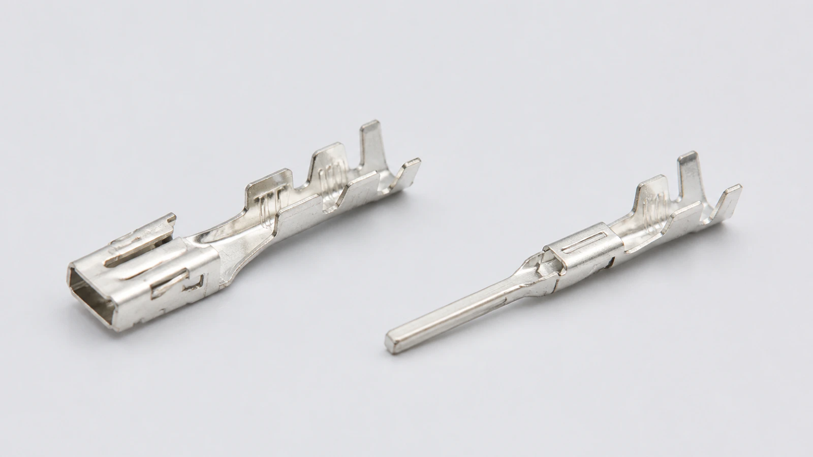
자동차 커넥터 단자 도금의 공정 경계
선도금은 코일 또는 스트립 상태에서 도금한 소재를 프레스 라인에 투입하는 순서입니다. 후도금은 블랭킹이나 성형으로 단자 형상을 만든 뒤 도금을 적용하는 순서입니다. 두 용어는 주석·은·금처럼 표면 금속을 구분하지 않으며, 전면도금과 선택도금의 구분도 아닙니다. 공정 순서와 도금 위치, 도금 적층은 서로 독립된 설계 축으로 관리해야 합니다.
후도금이라는 한 단어 안에도 여러 경계가 존재합니다. 블랭킹 후 도금하고 포밍하는 방식, 블랭킹과 포밍을 마친 캐리어 상태에서 도금하는 방식, 캐리어에서 완전히 분리한 뒤 도금하는 방식은 최종 노출면과 치구 조건이 서로 다릅니다. 도금 후 캐리어를 절단하면 마지막 분리 자국은 다시 모재가 드러날 수 있으므로 공정도에는 도금 시점과 최종 절단 시점을 함께 표시해야 합니다.
자동차 커넥터 단자 도금 공정을 결정할 때는 공법의 명칭보다 기능면이 어느 단계에서 만들어지는지를 먼저 확인합니다. 접촉 와이프 구역, PCB 삽입부, 실링 경계, 압착부와 납땜부가 프레스 전후 어느 시점에 완성되는지 정리하면 필요한 피복 범위와 검사 위치가 분명해집니다. 공급사 변경이나 공정 이전 시에도 이 경계가 같아야 기존 검증 결과를 비교할 수 있습니다.
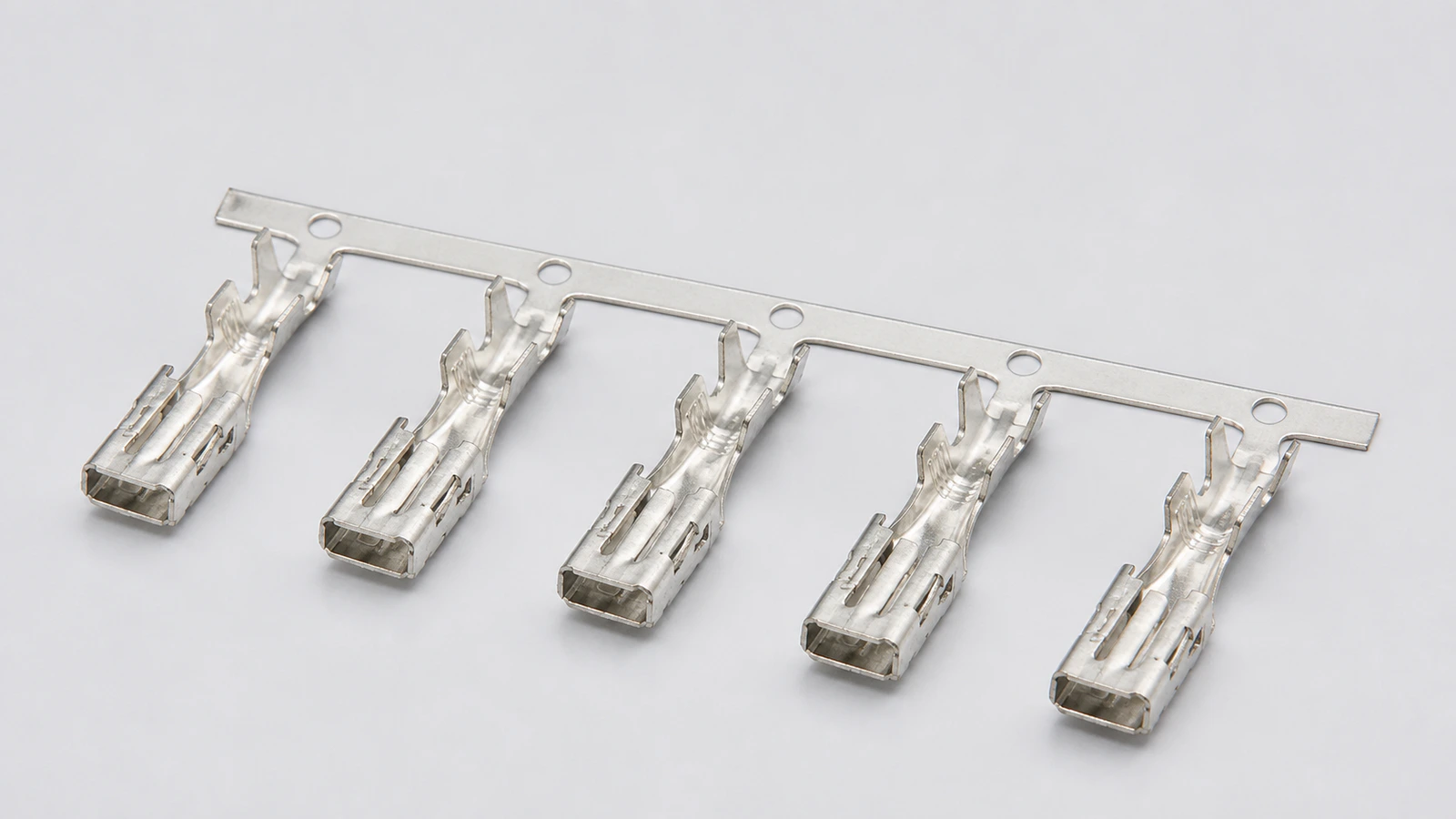
선도금 스트립과 절단면 노출
선도금 스트립은 연속 상태에서 표면처리와 두께 관리를 수행할 수 있어 프레스 공정과 재료 공급을 안정적으로 연결하기에 유리한 조건이 있습니다. 넓은 평면에 스트라이프나 선택 영역을 형성하고 파일럿 홀을 기준으로 도금 구역과 금형 피치를 맞출 수도 있습니다. 다만 소재 성적서의 평면 측정값이 완성 단자의 모든 기능면을 대표하는 것은 아닙니다.
타발은 기존 도금면을 절단하면서 판 두께 방향의 새로운 전단면을 만듭니다. 선도금 소재에서는 넓은 상·하면이 피복되어 있어도 새로 생긴 측면, 펀칭 홀 둘레와 캐리어 분리면에 모재가 노출될 수 있습니다. 굽힘 외측에서는 도금층이 인장되고 공구가 미끄러지는 위치에는 긁힘이나 재료전이가 생길 수 있으므로, 완성품에서 절단면과 성형면을 따로 확인해야 합니다.
노출 절단면이 보인다는 사실만으로 불량을 판정할 수는 없습니다. 그 면이 실제 접촉 자국에 들어오는지, 납땜 필렛이 형성되는 둘레인지, 응축수나 염수가 머무는 경로인지, 실링 경계를 가로지르는지를 기준으로 위험을 평가합니다. 기능경로 밖에 있고 사용환경과 전기적 간격이 관리된다면 선도금 구조도 충분히 검증 가능한 선택이 될 수 있습니다.
| 항목 | 선도금 | 후도금 | 설계 판단 |
|---|---|---|---|
| 공정 순서 | 스트립 도금 후 타발·성형 | 블랭킹 후 또는 블랭킹·성형 후 세정·활성화·도금 | 도금, 포밍과 최종 절단의 실제 순서 |
| 피복 경계 | 기존 평면은 피복되고 새 전단면은 노출될 수 있음 | 완성 형상의 측면 피복을 설계할 수 있음 | 절단면의 기능성 여부 |
| 성형 영향 | 최종 도금층이 타발·굽힘·공구 마찰을 통과 | 최종 포밍 후 도금이면 직접 변형을 피하지만 포밍 전 도금이면 이후 변형 가능 | 접촉면이 완성되는 시점 |
| 주요 위험 | 균열, 박리, 스미어링, 모재 노출 | 세정 불량, 치구 자국, 함몰부와 모서리 편차 | 완성품의 실제 불량모드 |
| 치수 영향 | 도금된 소재 두께를 금형 설계에 반영 | 완성 형상 위 석출과 모서리 빌드업을 반영 | 접촉 간극과 조립 형상 |
| 선택 영역 | 스트라이프·스폿형 스트립 적용 가능 | 마스킹·치구·부분 도금 적용 가능 | 기능영역과 위치 공차 |
| 경제성 | 연속 양산과 허용된 노출면 조건에서 유리할 수 있음 | 측면 기능 확보가 필요한 경우 추가공정 가치 발생 | 단가보다 총수율과 검증비 |
후도금 단자와 4면 피복
4면 피복의 적용 범위
후도금의 핵심은 프레스가 만든 측면과 접근 가능한 형상에 최종 표면층을 형성할 수 있다는 점입니다. 사각 핀은 상·하면과 양쪽 전단면을 구분할 수 있습니다. 이 네 면을 피복하는 구조를 4면 도금으로 설명하기도 합니다. 다만 이 표현은 특정 단면의 피복 범위를 뜻합니다. 모든 후도금 공법이나 복잡한 단자 형상의 전체 표면을 자동으로 보증하지는 않습니다.
함몰부와 치구 영향
박스형 암단자에는 내부, 좁은 틈, 접힌 이음부, 홀 안쪽, 치구 접촉부와 마스킹 경계가 있습니다. 각 위치는 전류 분포와 용액 교환 조건이 다릅니다. 돌출 모서리에는 석출이 집중될 수 있으며 함몰부에는 상대적으로 적게 형성될 수 있습니다. 캐리어 상태와 개별품 상태는 치구 방식도 다릅니다. 따라서 4면 피복 여부는 공정명만으로 판단하지 않습니다. 유효 단면과 측정 위치를 표시한 피복 맵으로 확인하는 편이 안전합니다.
도금·포밍 순서의 영향
최종 포밍을 마친 뒤 도금하면 최종 표면층은 프레스 공구와 직접 접촉하지 않습니다. 반면 블랭킹 후 도금하고 다시 포밍하면 최종 도금층이 굽힘과 공구 접촉을 거칩니다. 이 경로에는 같은 장점을 가정할 수 없습니다. 어느 경로든 성형유와 미세 버를 제거하는 세정이 필요합니다. 활성화, 수세와 건조도 새로운 관리 항목입니다. 치구 자국, 부품끼리의 접촉 흔적, 잔류 용액과 도금 후 취급 손상도 검토해야 합니다. 선도금과 후도금의 우열은 표면 수만으로 정하지 않습니다. 기능면 피복, 수율, 치수와 검증 비용을 함께 비교합니다.
| 기능영역 | 주요 위험 | 도면·사양 항목 | 검증 증거 |
|---|---|---|---|
| 결합 접촉부 | 마찰, 마모, 저항 변동 | 표면 적층, 기능영역, 최소 국부값, 접촉 경로 | 결합력, 저레벨 접촉저항, 반복 결합 |
| 절단 측면 | 모재 노출, 국부 부식 | 노출 허용구간, 측면 피복 범위, 모서리 기준 | 단면, 피복 맵, 환경 후 저항 |
| 스프링·굽힘부 | 도금 균열·박리 | 굽힘 반경, 재료 방향, 도금 경계 | 성형 후 단면, 접착 상태, 외관 |
| 랜스·하우징 삽입부 | 버 간섭, 과대 삽입력, 유지력 저하 | 버 방향, 랜스 형상, 도금 경계 | 단자 삽입·해제·유지력 |
| 압착부 | 전압강하, 인장력 부족 | 압착 높이, 표면 적합성, 와이어 범위 | 전압강하, 인장력, 압착 단면 |
| 납땜·용접부 | 젖음성·접합 불안정 | 마스킹 경계, 도금 종료선, 열공정 적합성 | 실제 공정의 납땜·용접 검증 |
기능영역별 도금 사양
단자 전체를 하나의 도금면으로 취급하면 필요한 성능과 불필요한 비용이 섞입니다. 결합 상대와 미끄러지는 접촉부는 마찰, 표면막, 내마모성과 저항 안정성이 중요합니다. 스프링부는 도금층 연성과 굽힘 건전성, 전이부는 전류 경로와 응력 집중, 압착부는 와이어와의 소성 결합, 납땜·용접부는 후속 열공정 적합성이 우선됩니다.
자동차 커넥터 단자 도금 사양에는 각 기능영역의 시작과 끝을 형상 기준으로 표시해야 합니다. 접촉 자국은 조립 공차와 와이프 거리에 따라 이동할 수 있으므로 이상적인 중심선만 지정해서는 부족합니다. 선택도금 경계, 절단면, 굽힘 외측, 랜스와 캐리어 분리 자국이 최악 조립조건에서 기능경로와 겹치는지를 도면 단계에서 확인합니다.
표면재와 하지층도 영역별 요구에서 출발합니다. 저레벨 신호, 고전류, 반복 결합, 고온 보관과 납땜 공정은 서로 다른 조합을 요구할 수 있습니다. 표면 금속의 이름만으로 성능을 단정하지 않고 상대 단자의 표면 조합, 윤활 상태, 목표 수명과 환경을 함께 규정해야 공급사 성적서와 실제 조립품 시험을 같은 언어로 비교할 수 있습니다.
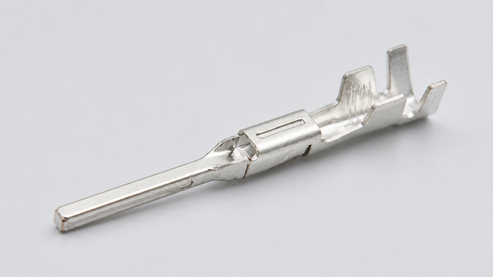
선택도금과 재료 사용 효율
선택도금은 표면재를 필요한 위치에만 배치하는 공간 설계입니다. 선도금 스트립에도 연속 스트라이프와 피치에 맞춘 스폿을 적용할 수 있고, 프레스 후 캐리어 상태나 개별 단자에도 마스킹과 치구를 이용한 부분 도금을 적용할 수 있습니다. 따라서 선택도금을 후도금의 동의어로 보거나 선도금을 전면도금으로 한정하면 공정 비교가 왜곡됩니다.
접촉부와 종단부가 서로 다른 기능을 가질 때는 영역별 적층을 나눌 수 있습니다. 예를 들어 접촉부의 귀금속계 표면과 압착·납땜부의 주석계 표면을 분리할 수 있지만, 실제 조합은 상대재, 사용 온도, 접촉하중과 후속 공정에 맞춰 검증해야 합니다. 서로 다른 금속을 결합면 양쪽에 임의로 섞거나 얇은 플래시층을 내구용 두꺼운 층과 동일하게 취급해서는 안 됩니다.
재료비 절감은 선택 폭과 위치 공차가 안정적으로 재현될 때 의미가 있습니다. 도금 경계가 접촉 트랙으로 이동하거나 마스킹 불량과 검사 복잡도가 증가하면 절감액보다 재작업과 품질비가 커질 수 있습니다. 귀금속 사용량, 도금 수율, 프레스 스크랩, 전환 손실, 검사 시간과 변경관리까지 합친 총비용으로 후보 공정을 비교하는 방식이 양산 판단에 적합합니다.
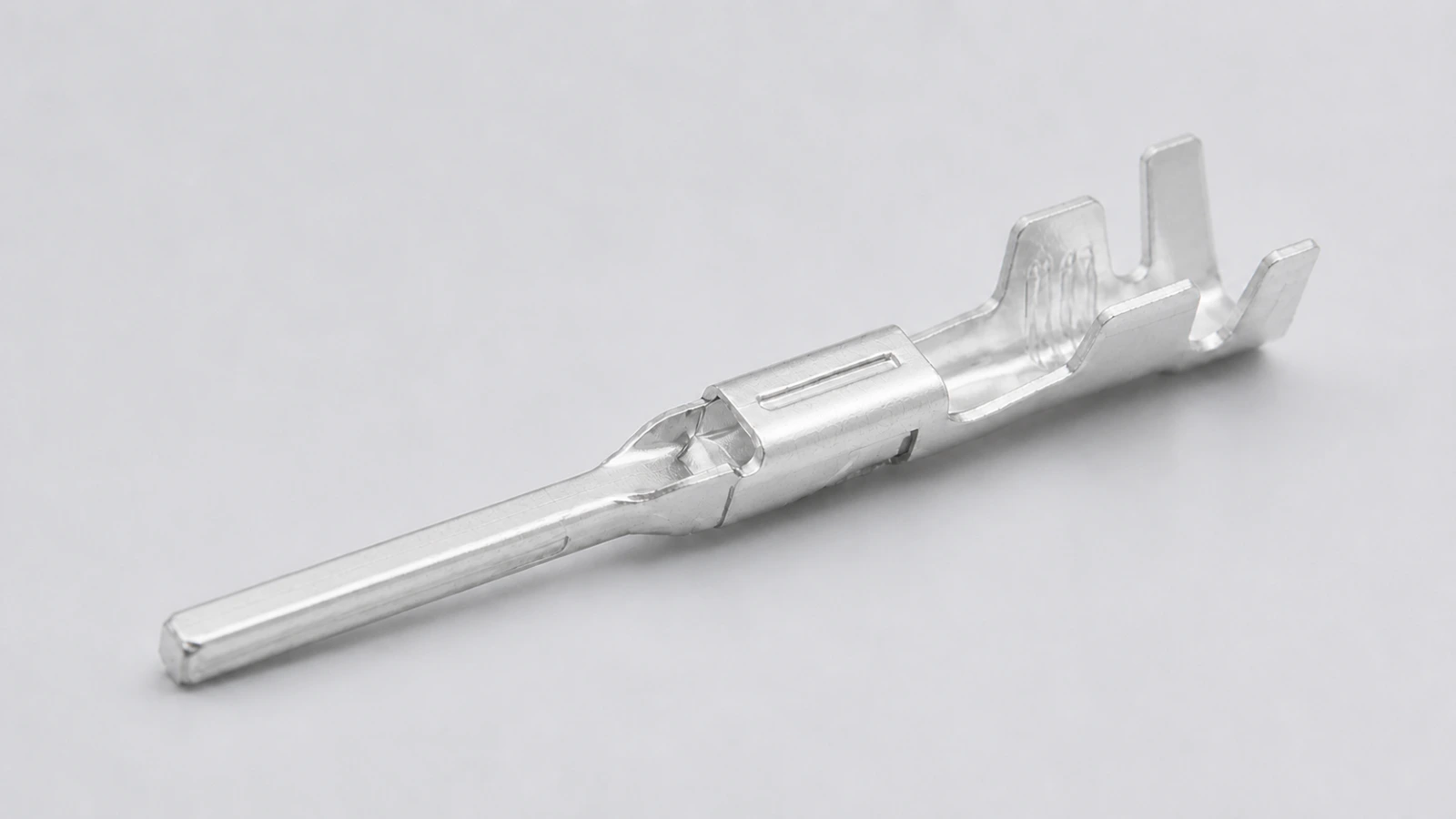
결합력·하우징 삽입력과 계면 마찰
현장에서 사용하는 삽입력이라는 표현에는 서로 다른 힘이 섞이기 쉽습니다. 수단자와 암단자의 금속 접촉계면에서 발생하는 힘은 커넥터 결합력의 일부입니다. 단자를 플라스틱 하우징에 넣을 때 랜스와 캐비티가 만드는 힘은 하우징 삽입력이며, 장착 뒤 단자가 빠지지 않도록 버티는 힘은 유지력입니다. 세 값은 시험 치구와 고장 원인이 다르므로 도면과 성적서에서 구분해야 합니다.
완성 커넥터의 결합력은 각 접점의 마찰과 접촉 정상력, 극수, 정렬 오차, 실의 마찰, 잠금장치와 레버 구조가 합쳐진 결과입니다. 최고 힘 하나만 기록하면 진입 모서리, 접촉 시작점, 실 압축과 잠금 구간을 분리하기 어렵습니다. 접점 단독과 완성 커넥터의 힘-변위 곡선을 각각 확보하고 첫 결합, 반복 결합 후, 환경노출 후의 변화와 분포를 비교하는 편이 원인 분석에 유리합니다.
자동차 커넥터 단자 도금의 시점만으로 결합력의 크기를 정할 수는 없습니다. 후도금으로 측면을 피복해도 표면 조성, 거칠기, 윤활, 접촉 정상력과 와이프 길이가 달라지면 마찰 거동이 바뀝니다. 반대로 선도금 구조라도 실제 접촉 트랙이 건전한 저마찰 표면에 형성되고 성형 손상이 관리되면 목표 조립성을 만족할 수 있습니다. 공정명보다 실제 상대 단자 조합과 완성품 곡선을 판단 근거로 사용해야 합니다.
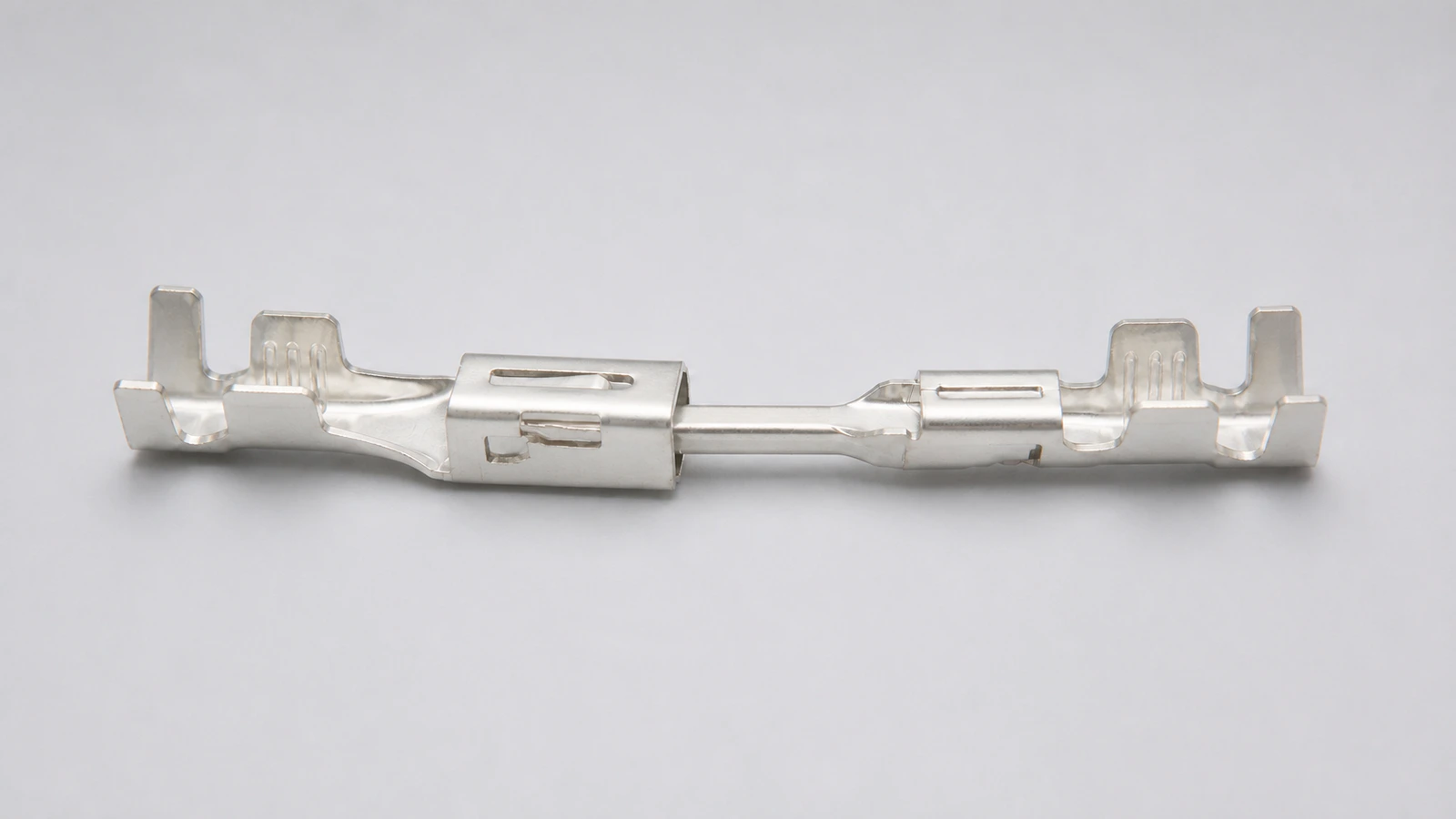
접촉저항과 프레팅 열화
접촉저항은 겉보기 접촉면 전체가 아니라 미세 돌기들이 실제로 맞닿는 좁은 지점에서 결정됩니다. 접촉 정상력과 와이핑은 표면막을 이동시키고 실제 금속 접촉점을 형성하지만, 과도한 힘과 이동은 도금 마모와 재료전이를 키울 수 있습니다. 표면재의 전도도만으로 초기 저항과 장기 안정성을 동시에 예측하기 어려운 이유입니다.
차량의 진동과 온도 변화가 미세한 상대운동을 만들면 접촉 트랙에서 프레팅 마모가 진행될 수 있습니다. 주석계에서는 연한 주석의 마모 분진이 접촉부에 축적되고 산화되면서 저항이 증가할 수 있습니다. 귀금속계는 기능 표층이 남아 있는 동안 산화 영향을 늦출 수 있지만, 관통 마모·박리·기공으로 하지층이나 모재가 노출되면 같은 보호를 기대할 수 없습니다. 어느 표면계든 정상력 저하와 접촉 트랙 이동을 마모 상태와 함께 확인해야 합니다.
절단면 노출은 그 면이 전류의 실제 접촉경로에 들어가거나 수분·오염의 이동경로가 될 때 신뢰성 변수로 작용합니다. 초기 접촉점이 건전한 도금 평면에 있고 절단면이 기능구역 밖에 있다면 초기 저항에 직접 영향을 주지 않을 수 있습니다. 판정은 저레벨 4선식 저항의 초기값, 반복 동작 중 순간 변화, 환경시험 후 안정값과 마모면 관찰을 동일 시편의 이력으로 연결해 수행합니다.
프레스 성형과 도금층 건전성
선도금층은 블랭킹, 엠보싱, 굽힘과 박스 성형을 통과하면서 압축·인장·전단을 받습니다. 굽힘 외측에서는 국부 박화와 균열이 나타날 수 있고 공구가 미끄러지는 구역에서는 긁힘, 스미어링과 표면 전이가 생길 수 있습니다. 재료 조질, 압연방향, 굽힘 반경, 금형 간극, 윤활과 표면층 연성이 함께 작용하므로 평판 소재의 접착성 결과만으로 완성 단자의 건전성을 대신할 수 없습니다.
후도금은 프레스가 최종 표면층을 직접 변형하지 않지만 가공유, 산화물, 버와 미세 분진이 남은 복잡 형상을 균일하게 전처리해야 합니다. 세정과 활성화가 부족하면 접착과 피복 연속성이 흔들리고, 과도한 전처리는 모재와 치수를 바꿀 수 있습니다. 치구 접촉 위치, 부품 간 가림, 내부 용액 잔류와 도금 후 취급 손상도 별도의 불량경로가 됩니다.
공정 비교는 선도금 평판과 후도금 시편 쿠폰이 아니라 실제 금형과 실제 형상으로 수행해야 합니다. 접촉부, 굽힘 외측, 전단면, 박스 내부, 랜스와 캐리어 분리면을 포함한 위치별 외관·단면·피복 연속성·접착 상태를 확인합니다. 초기 적합성뿐 아니라 열 이력과 반복 결합 후 박리, 균열과 마모의 진행을 평가해야 공정 고유의 위험과 조립 조건의 영향을 분리할 수 있습니다.
주석·주석합금 표면의 휘스커 가능성도 선도금과 후도금이라는 공정명만으로 판정할 수 없습니다. 모재와 하지층, 금속간화합물 성장, 잔류응력, 프레스·포밍 변형, 표면 손상, 습도와 온도사이클이 함께 작용합니다. 리플로와 니켈 하지층은 위험을 낮추는 수단이 될 수 있지만 휘스커가 없다는 보증은 아닙니다. IEC 60068-2-82:2019의 취지에 맞춰 실제 스탬핑·포밍이 끝난 완성 단계에서 평가하고, 과도한 시험 온도범위가 비현실적인 피막 균열이나 박리를 만들지 않았는지도 확인해야 합니다.
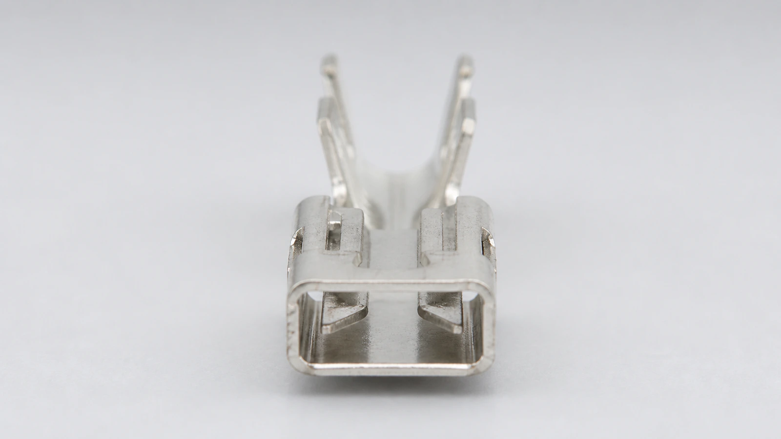
접촉부·전이부·압착부의 요구조건
결합·전이·스프링 영역
결합 접촉부 사양에는 표면 적층과 최소 국부 피복을 포함해야 합니다. 접촉 트랙, 상대 단자 조합과 윤활 상태도 하나의 사양으로 묶습니다. 전이부와 스프링부는 전류 경로를 유지하면서 반복 탄성변형을 견뎌야 합니다. 고온 응력완화도 고려해야 하므로 모재 조질, 형상과 표면 건전성을 함께 봅니다. 동일한 표면재라도 기능영역이 달라지면 허용 가능한 노출면과 검사 증거가 달라집니다.
압착·납땜·용접 영역
압착부에서는 단자 표면보다 와이어와 배럴의 소성변형이 지배적인 경우가 많습니다. 압착 높이, 도체 브러시와 인장력도 핵심 관리 항목입니다. 납땜·용접부는 표면 조성, 오염, 보관 열화와 실제 열프로파일이 접합 품질을 좌우합니다. PCB 핀의 4면 피복은 둘레 젖음성을 개선할 수 있습니다. 다만 실제 솔더 합금, 플럭스, PCB 열용량과 프로파일을 사용해 확인해야 합니다. ASTM B678-25는 주석-납 솔더와 로진 플럭스를 이용한 정성적 합격·불합격 시험입니다. 따라서 무연 양산 공정을 대신할 수 없습니다. 크림프 전용 단자에 납땜성 이점을 적용해서는 안 됩니다. PCB 핀의 4면 피복 결과를 와이어 압착 신뢰성으로 확대해서도 안 됩니다.
도면과 구매 사양
자동차 커넥터 단자 도금 도면은 표면 금속과 두께만 나열하지 않습니다. 기능영역, 피복 제외구역, 절단면 허용상태, 공정 순서와 측정 맵을 연결해야 합니다. 합격값은 단자 크기와 사용 회로, 고객 규격에 따라 달라질 수 있습니다. 따라서 보편적인 힘·저항·두께 숫자를 임의로 넣지 않습니다. 구매 사양에는 실제 요구조건과 시험방법을 명시합니다. 시료 수, 측정 위치와 변화량 판정기준도 함께 기록합니다.
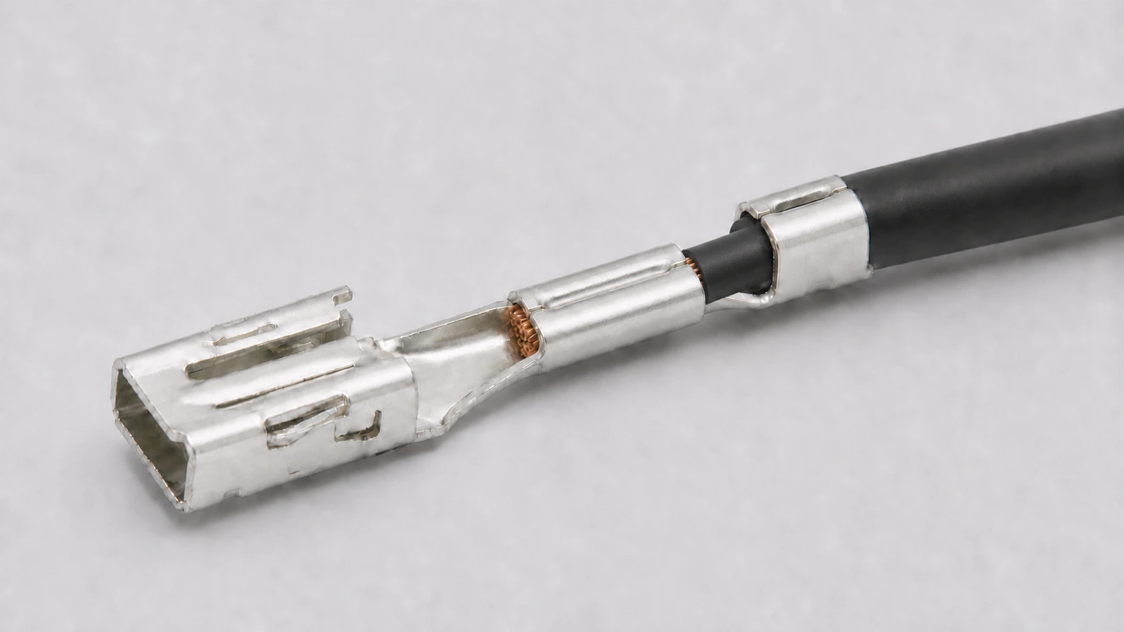
공정 선택 매트릭스와 양산 검증
절단면의 기능성
공정 선택의 첫 번째 질문은 새로 생긴 절단면이 기능경로에 들어오는지 여부입니다. 절단면이 접촉 트랙, 납땜 둘레, 실링 경계와 부식 경로에서 벗어나야 합니다. 성형 후 표면 건전성까지 확보되면 선도금은 합리적인 후보가 될 수 있습니다. 반대로 측면 피복이 기능적으로 필요하면 후도금 후보를 검토합니다. 최종 접촉면의 프레스 손상을 피해야 하는 경우도 같습니다. 이때 접근하기 어려운 면과 마지막 절단 자국까지 실제 피복 범위를 확인합니다.
초도 시편 검증
초도 검증은 공정도, 소재와 조질, 금형 조건, 도금 적층, 기능영역을 고정한 뒤 진행합니다. ASTM B568-98(2021)에 따른 XRF와 ASTM B487-24 단면 관찰을 함께 적용합니다. 측정 위치는 평면뿐 아니라 접촉부, 전단면, 굽힘, 박스 내부와 선택도금 경계에 배치합니다. 필요에 따라 ASTM B571-23 접착성과 ASTM B809-25 기공 평가를 연결합니다. 접점 단독과 완성 커넥터의 힘-변위 곡선을 같은 로트와 시편 번호로 연결합니다. 초기·반복·환경 후 접촉저항과 압착 또는 납땜·용접 결과도 같은 이력으로 관리합니다. 그러면 표면처리와 조립 변수를 구분할 수 있습니다.
시험표준의 적용 범위
시험표준은 목적별로 구분합니다. 저레벨 접촉저항에는 IEC 60512-2-1을 적용합니다. 실과 잠금장치 영향을 제외한 접점 삽입·인발력은 IEC 60512-13-2로 확인합니다. 이를 포함한 완성 커넥터 결합·분리력은 IEC 60512-13-1로 분리합니다. ISO 8092-2:2023은 전압 클래스 A의 차내 와이어링 하니스 커넥터 범위입니다. 전자장치 내부 연결과 데이터 무결성 시험은 포함하지 않습니다. 자동차 시스템 검증은 이 적용 범위 또는 SAE/USCAR-2 Revision 9와 최신 변경문서 등을 따릅니다. 해당 고객 규격도 함께 적용해야 합니다. 그러나 표준명만으로 보편 합격값이 생기는 것은 아닙니다. 시험 강도와 합격치는 제품·고객 사양에 고정해야 합니다. ASTM B117-26 염수분무 시간을 차량 사용연수로 환산해서도 안 됩니다.
양산 변경관리
자동차 커넥터 단자 도금의 최종 선택은 한 번의 합격시험으로 확정하지 않습니다. 양산 변동을 포함한 공정범위로 확정해야 합니다. 도금 업체, 욕 조성, 표층·하지층, 윤활·패시베이션 중 하나가 바뀌면 영향평가가 필요합니다. 금형, 굽힘 반경, 선택영역 위치와 캐리어 절단 순서의 변경도 같습니다. 각 변경에는 재검증 범위를 정해야 합니다. 성적서에는 평균값만 남기지 않습니다. 최소값, 분포, 측정 위치, 시험 전후 변화와 불량모드를 기록해야 장기 품질과 변경관리가 이어집니다.
공정 선택의 판단 축
선도금과 후도금은 서로의 상위·하위 공법이 아닙니다. 선택은 설계를 지배하는 요구에 따라 달라집니다. 주요 판단 축은 기능면 피복, 성형 손상, 조립력과 접촉 신뢰성입니다. 후속 접합과 총비용도 함께 비교합니다. 먼저 도면, 피복 맵, 공정도와 검증 계획을 맞춥니다. 그다음 공급사별 실제 생산 결과를 비교해야 재현성 높은 판단 기준을 확보할 수 있습니다.
English Technical Overview
Automotive connector terminal plating is not simply a choice of surface color or plating metal. It is an engineering decision that defines the process sequence before and after stamping and establishes the coverage boundary of each functional surface. Even with the same copper alloy and the same finish, exposed cut edges, damage at formed regions, selective-plating position, and inspection methods change depending on whether a plated strip is stamped and formed or the finished geometry is plated afterward.
The assembly behavior of a multi-position connector is influenced not only by friction and contact normal force at the mating interface, but also by circuit count, housing alignment, seals, and locking features. Contact reliability cannot be judged from one initial resistance value either. Coverage of the functional zone, coating integrity after forming, resistance change after repeated mating and vibration, and compatibility of the crimp, solder, or weld zone must be connected through the same drawing and specimen history.
Process Boundaries for Automotive Connector Terminal Plating
Pre-plating means that a coil or strip is plated before it enters the stamping line. Post-plating means that plating is applied after blanking or forming has created the terminal geometry. These terms do not identify a surface metal such as tin, silver, or gold, and they do not distinguish overall plating from selective plating. Process sequence, plating location, and plating stack must be controlled as separate engineering axes.
Several different boundaries can exist within the single term post-plating. Plating after blanking but before forming, plating an already formed terminal while it remains on a carrier, and plating an individual terminal after complete carrier separation can leave different final exposed surfaces and require different fixturing. If the carrier is cut after plating, the final break-off witness can expose the substrate again. The process flow should therefore identify both the plating stage and the final cutting stage.
The first task in selecting the process is to determine when each functional surface is created. Mapping the mating wipe zone, PCB insertion section, sealing boundary, crimp zone, and solder zone to the relevant stamping or finishing stage clarifies the required coverage and inspection locations. The same boundary definition is also essential when comparing results after supplier transfer or process relocation.
Pre-Plated Strip and Exposed Cut Edges
A pre-plated strip can connect surface treatment, thickness control, and stamping supply in one continuous production route. Stripe plating or other selected regions can be formed on the broad strip surfaces, and the plating location can be registered to die pitch through pilot features. The measurement on the flat incoming-material certificate, however, does not represent every functional surface on the finished terminal.
Blanking cuts through the existing plated surface and creates a new sheared face through the stock thickness. Broad top and bottom faces may remain coated, while newly created sidewalls, pierced-hole edges, and carrier break-off faces expose the substrate. The coating can be stretched on the outside of a bend, and scratches or material transfer can develop where tools slide against it. Cut surfaces and formed surfaces therefore require separate inspection on the completed part.
The visible presence of an exposed edge is not, by itself, a failure criterion. Its significance depends on whether it enters the actual contact scar, forms part of the solder fillet perimeter, lies along a path where condensate or road salt can remain, or crosses the sealing boundary. A pre-plated structure can be a fully valid candidate when the edge remains outside the functional path and the environmental and electrical-clearance requirements are controlled.
Post-Plated Terminals and Four-Surface Coverage
Scope of Four-Surface Coverage
The principal advantage of post-plating is its ability to apply the final surface layer to side faces and other accessible stamped geometry. A rectangular pin has two broad faces and two sheared sides. Coverage of these four faces is sometimes described as four-surface plating. However, the term describes the coverage of a particular cross-section. It does not automatically guarantee complete coverage of every complex terminal geometry or every post-plating process.
Effects of Recesses and Fixturing
A box receptacle has an interior, narrow gaps, folded seams, hole interiors, rack-contact locations, and masking boundaries. Current distribution and solution exchange differ at each location. Deposition can concentrate at projecting edges and be relatively lower in recessed regions. Carrier-plated and individually plated parts also use different fixturing. Four-surface coverage should not be inferred from the process name alone. It is safer to confirm coverage with a map that identifies the effective cross-sections and measurement locations.
Plating and Forming Sequence
When plating follows final forming, the final finish does not pass directly through the forming tools. By contrast, plating after blanking and forming afterward subjects the final coating to bending and tool contact. The same advantage cannot be assumed for this route. Either route requires cleaning to remove forming lubricant and fine burr debris. Activation, rinsing, and drying also become new control items. Rack marks, part-to-part contact, retained solution, and handling damage after plating require evaluation. Pre-plating and post-plating should not be ranked by surface count alone. Functional coverage, yield, dimensions, and validation cost must be compared together.
| Attribute | Pre-plating | Post-plating | Engineering decision |
|---|---|---|---|
| Process sequence | Strip plating before stamping and forming | Cleaning, activation, and plating after blanking or after blanking and forming | Actual order of plating, forming, and final cutting |
| Coverage boundary | Existing broad faces remain coated while new sheared faces can be exposed | Side coverage can be engineered on the finished geometry | Functional relevance of the cut edge |
| Forming exposure | The final coating passes through blanking, bending, and tool friction | Plating after final forming avoids direct deformation; plating before forming can still be deformed later | Stage at which the mating surface is completed |
| Principal risks | Cracking, peeling, smearing, and substrate exposure | Cleaning defects, rack marks, and recess or corner variation | Actual failure mode on the completed part |
| Dimensional effect | Coated stock thickness enters die design | Deposit growth and edge build-up enter the finished dimensional stack | Contact gap and assembly geometry |
| Selective regions | Stripe or registered spot plating can be applied to strip | Masking, fixturing, and partial plating can be applied | Functional zone and position tolerance |
| Economics | Can be effective for continuous volume when exposed edges are acceptable | Added processing can be justified when side coverage is functional | Total yield and validation cost rather than piece price alone |
Plating Specifications by Functional Zone
Treating the entire terminal as one plated surface mixes necessary performance with unnecessary cost. The mating area requires control of friction, surface films, wear, and resistance stability. The spring zone requires deposit ductility and bend integrity; the transition zone requires a stable current path and controlled stress concentration; the crimp zone requires plastic joining to the wire; and the solder or weld zone requires compatibility with the subsequent thermal joining process.
The beginning and end of each functional zone should be defined from physical geometry. Because the contact scar can move with assembly tolerance and wipe distance, an ideal centerline alone is not sufficient. The selective-plating boundary, cut edge, outside bend, locking lance, and carrier break-off witness should be checked against the functional path under the worst relevant assembly condition.
Surface metal and underlayer decisions also begin with zone-specific requirements. Low-level signals, high current, repeated mating, high-temperature storage, and soldering can call for different combinations. Performance should not be inferred from the name of a finish alone. The mating finish combination, lubricant status, target life, and environment must be specified together so that supplier certificates and assembled-product tests can be compared on the same basis.
Selective Plating and Material-Use Efficiency
Selective plating is the spatial design of applying a finish only where it is needed. Continuous stripes and pitch-registered spots can be applied to pre-plated strip, while masking and fixturing can be used for partial plating on a post-stamped carrier or an individual terminal. Treating selective plating as a synonym for post-plating, or assuming that pre-plating always means overall plating, distorts the process comparison.
When mating and termination regions have different functions, their plating stacks can be separated. A precious-metal finish at the mating area and a tin-based finish at the crimp or solder area can be considered, but the actual combination must be validated against the mating material, operating temperature, contact force, and downstream process. Dissimilar finishes should not be paired at a contact interface without evaluation, and a thin flash should not be treated as equivalent to a thicker durability finish.
Material savings are meaningful only when selective width and registration are reproduced consistently. If a plating boundary shifts into the contact track, or if masking defects and inspection complexity increase, rework and quality cost can exceed the material saved. Candidate processes should be compared by total cost, including precious-metal use, plating yield, stamping scrap, changeover loss, inspection time, and change control.
Mating Force, Housing Insertion Force, and Interface Friction
The term insertion force often combines different mechanical quantities. Force generated at the metal-to-metal interface between male and female terminals contributes to connector mating force. The force created by a locking lance and cavity when a terminal is loaded into a plastic housing is terminal-to-housing insertion force. The force that prevents the terminal from being pulled out after installation is retention force. Their fixtures and failure causes differ, so they should be separated on drawings and test records.
Completed-connector mating force combines the friction and normal force of each contact with circuit count, alignment error, seal friction, locks, and lever features. A single peak value does not distinguish the lead-in edge, first metal contact, seal compression, and lock engagement. Recording force-displacement curves for the isolated contact interface and for the completed connector, and comparing first mating, post-durability, and post-environment distributions, provides more useful evidence for root-cause analysis.
Process timing alone cannot determine mating force. Side coverage obtained through post-plating can still produce different friction when surface composition, roughness, lubrication, normal force, or wipe length changes. A pre-plated design can also meet the assembly target when its contact track lies on an undamaged, low-friction surface and forming damage is controlled. The actual mating pair and completed-product force curve should take precedence over the process label.
Contact Resistance and Fretting Degradation
Contact resistance is governed by the small asperity spots that carry current rather than by the full apparent mating area. Contact normal force and wiping can displace surface films and establish metallic contact, while excessive force or movement can increase coating wear and material transfer. This is why bulk conductivity alone cannot predict both initial resistance and long-term stability.
Vehicle vibration and temperature change can create micromotion and fretting wear in the contact track. In a tin-based system, soft tin wear debris can accumulate and oxidize in the interface, increasing resistance. A precious-metal system can delay oxidation effects while its functional top layer remains intact, but the same protection cannot be assumed after wear-through, delamination, or porosity exposes an underlayer or substrate. For either finish system, loss of normal force and migration of the contact track must be evaluated together with the wear state.
An exposed cut edge becomes a reliability variable when it enters the real current path or provides a route for moisture and contamination. If the initial contact lies on a sound plated broad face and the cut edge remains outside the functional zone, it may not directly affect initial resistance. Evaluation should connect initial four-wire low-level resistance, transient behavior during repeated operation, stable post-environment resistance, and wear-surface observations through the history of the same specimens.
Press Forming and Coating Integrity
A pre-plated layer experiences compression, tension, and shear as it passes through blanking, embossing, bending, and box forming. Local thinning or cracking can occur at the outer bend, while scratches, smearing, and material transfer can occur where a tool slides across the surface. Stock temper, rolling direction, bend radius, die clearance, lubrication, and deposit ductility act together. Adhesion results from flat incoming material cannot replace integrity checks on the finished terminal.
Post-plating avoids direct deformation of the final finish by stamping tools, but it requires uniform preparation of a complex geometry that can retain lubricant, oxide, burrs, and fine debris. Insufficient cleaning or activation can undermine adhesion and continuity, while excessive preparation can alter the substrate or dimensions. Rack-contact position, shielding between parts, retained solution in internal regions, and handling damage after plating create additional failure paths.
The comparison should use real die-produced geometry rather than a pre-plated flat coupon and a post-plated test coupon. Inspection locations should include the mating zone, outer bend, sheared face, box interior, locking lance, and carrier break-off witness. Evaluating delamination, cracking, and wear progression after thermal exposure and repeated mating, as well as at initial qualification, helps separate process-specific risks from assembly effects.
Whisker propensity on tin and tin-alloy finishes cannot be determined from the pre-plating or post-plating label alone. Substrate and underlayer, intermetallic growth, residual stress, stamping and forming strain, surface damage, humidity, and temperature cycling act together. Reflow and a nickel underlayer can be risk-reduction measures, but they do not guarantee a whisker-free result. Consistent with IEC 60068-2-82:2019, evaluation should use the finished stage after the actual stamping and forming operations, and the test should also confirm that an excessive temperature range has not introduced non-representative coating cracks or delamination.
Requirements for Mating, Transition, and Crimp Zones
Mating, Transition, and Spring Zones
The mating-interface specification should include the finish stack and minimum local coverage. It should also combine the contact track, mating finish combination, and lubrication status. The transition and spring regions must retain a current path while tolerating repeated elastic motion. High-temperature stress relaxation must also be considered, so substrate temper, geometry, and finish integrity are evaluated together. Even with the same surface metal, allowable exposed areas and inspection evidence change with the functional zone.
Crimp, Solder, and Weld Zones
In the crimp zone, wire-to-barrel plastic deformation can dominate over the terminal surface itself. Crimp height, conductor brush, and pull performance are also key control items. In a solder or weld zone, surface composition, contamination, storage aging, and the actual thermal profile govern joint quality. Four-surface coverage of a PCB pin can improve perimeter wetting. However, it must be checked with the actual solder alloy, flux, PCB thermal mass, and profile. ASTM B678-25 is a qualitative go/no-go method using tin-lead solder and rosin flux. It therefore cannot replace validation of a lead-free production process. A solderability benefit must not be assigned to a crimp-only terminal. Four-surface coverage results for a PCB pin must not be generalized as proof of wire-crimp reliability.
Drawing and Purchasing Specification
The terminal-plating drawing should not list only the surface metal and thickness. It must connect functional zones, excluded areas, permitted cut-edge conditions, process sequence, and a measurement map. Acceptance values can vary with terminal size, circuit duty, and customer specification. Universal force, resistance, or thickness values should therefore not be inserted arbitrarily. The purchasing specification should state the actual requirements and test methods. It should also record specimen count, measurement locations, and change-based acceptance criteria.
| Functional zone | Principal risk | Drawing and specification item | Verification evidence |
|---|---|---|---|
| Mating interface | Friction, wear, and resistance variation | Finish stack, functional zone, minimum local value, and contact path | Mating force, low-level contact resistance, and mating durability |
| Sheared side | Substrate exposure and localized corrosion | Permitted exposure, side-coverage boundary, and edge criterion | Cross-section, coverage map, and post-environment resistance |
| Spring and bend zone | Coating crack and delamination | Bend radius, material direction, and plating boundary | Post-forming cross-section, adhesion condition, and appearance |
| Locking lance and housing interface | Burr interference, excessive insertion force, and loss of retention | Burr direction, lance geometry, and plating boundary | Terminal insertion, release, and retention force |
| Crimp zone | Voltage drop and inadequate pull strength | Crimp height, finish compatibility, and wire range | Voltage drop, pull force, and crimp cross-section |
| Solder or weld zone | Poor wetting and unstable joint formation | Masking boundary, finish termination, and thermal-process compatibility | Solder or weld validation with the actual process |
Process-Selection Matrix and Production Validation
Functional Relevance of Cut Edges
The first process-selection question is whether a newly created cut edge enters a functional path. The edge must remain outside the contact track, solder perimeter, sealing boundary, and corrosion path. Pre-plating can be a rational candidate when post-forming surface integrity is also demonstrated. When side coverage is functional, post-plating should be considered. The same applies when press damage to the final mating surface must be avoided. The actual coverage of difficult-to-access regions and the final break-off witness still requires confirmation.
Initial-Sample Validation
Initial validation begins by fixing the process flow, material and temper, die condition, plating stack, and functional zones. XRF following ASTM B568-98(2021) and cross-sectional observations following ASTM B487-24 are applied together. Measurement locations include the mating area, sheared side, bend, box interior, and selective-plating boundary in addition to broad surfaces. ASTM B571-23 adhesion and ASTM B809-25 porosity evaluations are added where applicable. Force-displacement curves from isolated contacts and completed connectors are linked by lot and specimen number. Initial, durability, and post-environment contact resistance share that history with crimp or solder/weld results. This linkage helps separate finishing variables from assembly variables.
Scope of Test Standards
Test standards should be separated by purpose. IEC 60512-2-1 addresses low-level contact resistance. IEC 60512-13-2 covers contact insertion and withdrawal force without seals and locking features. IEC 60512-13-1 separately covers completed-connector engagement and separation with those features included. ISO 8092-2:2023 covers voltage-class-A connectors for on-board wiring harnesses. It does not cover internal electronic-device connections or data-integrity testing. Automotive-system validation should follow that scope or SAE/USCAR-2 Revision 9 and its current change letters. The applicable customer specification must also be applied. However, a standard name does not create a universal acceptance limit. Severities and acceptance criteria must be fixed in the product or customer specification. ASTM B117-26 salt-fog exposure time must not be converted into vehicle service years.
Production Change Control
The final choice is not established by one passing test. It must be established as a production window that includes normal variation. A change in plating supplier, bath chemistry, top finish, underlayer, lubrication, or passivation requires an impact review. The same applies to changes in the die, bend radius, selective-zone position, or carrier-cut sequence. Each change requires a defined revalidation scope. Certificates should not retain averages alone. Minimum values, distributions, measurement locations, before-and-after changes, and failure modes support long-term quality and change control.
Process-Selection Criteria
Pre-plating and post-plating are not superior and inferior versions of the same process. The selected route depends on the requirements that govern the design. Primary decision factors are functional coverage, forming damage, assembly force, and contact reliability. Downstream joining and total cost must also be compared. The drawing, coverage map, process flow, and validation plan are aligned first. Supplier-specific production results are then compared to establish the most reproducible decision basis.
추가 정보
검색엔진용 요약
자동차 커넥터 단자의 선도금과 후도금은 표면 금속의 우열이 아니라 프레스 전후의 공정 순서와 기능면 피복 범위를 선택하는 문제입니다. 절단면 위치, 4면 피복, 성형 손상, 결합력, 접촉저항과 압착·납땜 조건을 실제 도면과 양산 검증으로 연결해야 합니다.
핵심 포인트
- 선도금과 후도금은 도금 금속이 아니라 프레스 전후의 공정 순서를 구분합니다.
- 선도금 스트립은 타발 과정에서 새로운 절단 측면과 캐리어 분리면을 만들 수 있습니다.
- 4면 도금은 특정 단면의 네 면 피복을 뜻하며 복잡 형상의 모든 면 균일피복을 보증하지 않습니다.
- 커넥터 결합력, 단자-하우징 삽입력과 단자 유지력은 서로 다른 시험 항목입니다.
- 후도금도 세정, 치구 자국, 함몰부 두께 편차와 최종 절단 자국을 검증해야 합니다.
- 최종 선택은 피복 맵, 힘-변위 곡선, 접촉저항, 단면과 후속 접합 결과를 같은 시편 이력으로 비교해 확정합니다.
FAQ
선도금과 후도금 중 항상 더 신뢰성 높은 공정이 있습니까?
공정명만으로 우열을 정할 수 없습니다. 절단면이 기능경로에 들어오는지, 성형 후 표면이 건전한지, 완성품의 결합력과 환경 후 저항이 요구조건을 만족하는지로 판단해야 합니다.
후도금이면 단자의 모든 면이 같은 두께로 덮입니까?
그렇지 않습니다. 모서리, 함몰부, 박스 내부, 치구 접촉부와 마스킹 경계는 피복 상태가 달라질 수 있으므로 위치별 XRF와 단면으로 실제 분포를 확인해야 합니다.
선도금 단자에 노출된 절단면은 모두 불량입니까?
노출면의 위치와 사용환경에 따라 달라집니다. 실제 접촉 트랙, 납땜 둘레, 실링 경계나 부식 경로에 포함되는지를 확인한 뒤 허용 여부와 검증 조건을 정합니다.
후도금을 적용하면 커넥터 결합력이 자동으로 낮아집니까?
자동으로 낮아지지 않습니다. 표면 조성, 거칠기, 윤활, 접촉 정상력, 와이프 길이, 극수와 하우징 구조가 함께 영향을 주므로 실제 상대 단자와 완성품 곡선으로 확인합니다.
커넥터 결합력과 단자 삽입력은 같은 값입니까?
같지 않습니다. 커넥터 결합력은 수·암 접점과 실·잠금 구조가 합쳐진 힘이고, 단자-하우징 삽입력은 단자를 캐비티에 장착할 때 발생하는 힘입니다. 유지력도 별도 항목입니다.
도금 두께는 XRF 측정만으로 판정할 수 있습니까?
평면 양산 관리에는 활용할 수 있지만 절단면, 곡률, 함몰부와 다층 구조는 형상 영향을 받을 수 있습니다. 초도 단계에서 위치별 단면과 상관성을 확보하고 측정 치구와 교정조건을 고정해야 합니다.
관련 주제
기능영역과 선택도금 경계
접촉 트랙, 스프링부, 압착부와 후속 접합부를 분리하면 각 영역의 피복 범위와 측정 위치를 명확하게 지정할 수 있습니다.
절단면과 4면 피복 맵
공정명 대신 유효 단면 그림에 허용 노출면, 피복 필수면, 최종 캐리어 절단 위치와 단면 측정점을 표시하는 방식이 재현성 높습니다.
조립력과 접촉 신뢰성의 통합 판정
힘-변위 곡선, 저레벨 접촉저항, 환경 후 변화와 마모면을 같은 로트와 시편 번호로 연결하면 공정 차이와 조립 산포를 구분할 수 있습니다.
내부 링크
관련 키워드
선도금 단자, 후도금 단자, 4면 도금, 절단면 피복, 선택도금, 자동차 단자, 프레스 단자, 커넥터 결합력, 하우징 삽입력, 접촉저항, 프레팅 마모, 양산 검증