
튜블라 전기접점 리벳팅:
중공 끝단 성형과 체결 품질
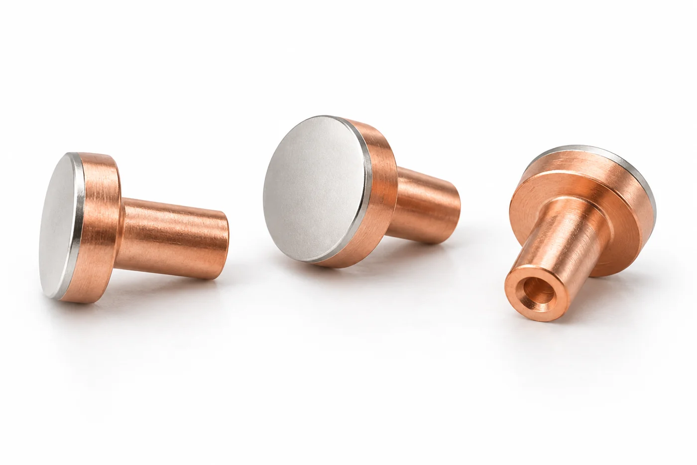
튜블라 전기접점은 머리 반대쪽의 중공 끝단을 벌려 캐리어에 고정하는 접점 부품입니다. 상대 접점과 맞닿는 작업면을 유지하면서 끝단에 체결부를 만들어야 하므로, 중공 치수와 소재의 성형성, 공구 지지와 조립 조건을 함께 검토합니다. 체결부의 외관뿐 아니라 유지력·접합부 저항·접점 높이가 함께 품질을 결정합니다.
움직이는 3D는 머리를 아래에 지지한 상태에서 위쪽 중공 끝단을 벌리고 눌러 고정하는 과정을 보여 줍니다. 이어지는 사진, 회전·확대 가능한 단면·성형 비교 3D와 본문은 반중공 형상과 소재 구성을 구분하고, 치수·공정 조건부터 불량 분석, 검사·검증과 제작 도면까지 연결합니다.
중공 끝단의 변형
작업면과 체결부를 나누고, 맹공 깊이·벽 두께·돌출량의 역할을 설명합니다.
소재와 리벳팅 조건
재료 구성·공구 운동·받침·하중과 변위를 완성 조립체의 품질에 연결합니다.
검사에서 제작 의뢰까지
단면·유지력·저항과 사용 조건 검증을 도면과 승인 기준으로 정리합니다.
01중공 접점의 구조와 기능
튜블라 전기접점의 구조
튜블라 전기접점은 축의 끝부분에 있는 중공부를 리벳팅하여 캐리어에 고정할 수 있는 접점 부품입니다. 상대 접점과 맞닿는 머리의 작업면은 전류를 연결하고, 반대쪽 축 끝단은 조립체에서 접점이 빠지지 않도록 체결 형상을 만듭니다. 같은 부품 안에서도 전기적 기능면과 소성변형시키는 체결부를 나누어 설계해야 합니다.
이 글에서 다루는 형상은 머리 하나와 동축의 원통형 축 하나로 이루어집니다. 축 끝의 구멍은 머리까지 관통하지 않고 일정 깊이에서 끝나는 맹공이며, 여기서는 이를 반중공 접점 리벳의 형상으로 설명합니다. 튜블라와 세미튜블라의 분류 기준은 제조 자료마다 다를 수 있으므로 이름만으로 관통 여부를 단정하지 말고 단면과 구멍 깊이로 확인해야 합니다.
맹공과 관통공
머리와 구멍 바닥 사이에는 재료가 남아 있어 전기접촉용 작업면을 유지합니다. 별도의 관통형 튜브나 아일릿 구조를 검토한다면 남아 있는 단면, 성형 도구와 전류 경로를 다시 확인해야 합니다. 두 형상은 사진에서 끝단 구멍이 보인다는 이유만으로 같은 부품이 되지 않습니다.
구멍이 막혀 있다는 뜻의 맹공과 한쪽에서 당겨 체결하는 블라인드 리벳은 다른 개념입니다. 여기서는 미리 만든 캐리어 홀에 접점을 넣고 머리 쪽 받침과 끝단 쪽 공구로 성형합니다. 따라서 공구 접근성과 지지를 검토할 때에는 조립체의 양쪽 공간을 확인해야 합니다.
중공부는 체결할 때 움직일 재료의 위치를 정합니다. 펀치가 끝단에 작용하면 얇은 원통 벽이 바깥으로 벌어지고 말리면서 캐리어 홀보다 큰 체결부를 형성할 수 있습니다. 구멍이 있다고 해서 성형 하중이나 접점 수명이 일정 비율로 개선되는 것은 아니며, 벽 두께와 소재 상태, 돌출 길이와 공구 형상을 함께 보아야 합니다.
거꾸로 놓은 조립 방향
움직이는 3D에서는 접점 머리를 아래쪽에 놓고 중공 끝단을 위쪽으로 향하게 배치합니다. 위에서 내려오는 펀치는 이 중공 끝단을 성형하며, 아래의 받침은 머리 쪽에서 반력을 지지합니다. 화면의 위쪽에 새로 만들어지는 넓은 부분은 전기접촉용 머리가 아니라 리벳팅으로 형성된 체결부입니다.
단계별로 볼 때에는 삽입 전 형상, 캐리어에 안착한 상태, 끝단이 벌어지는 과정과 공구가 물러난 완성 상태를 구분합니다. 머리의 작업면과 접점재 경계는 성형 전후에 유지되어야 하며, 체결부가 커지는 대신 작업면이 눌려 바뀌는 동작은 목표 공정이 아닙니다. 모델은 이 변형 위치를 설명하는 형상 표현이며 실제 하중이나 응력 해석값을 제시하지 않습니다.
중공 끝단의 리벳팅 공정
INTERACTIVE 3D캐리어의 구멍에 섕크를 삽입하고, 하부 받침이 원래 접점 머리를 지지합니다.
체결력과 전류 경로
캐리어에 삽입한 접점은 기존 머리와 새로 성형한 체결부 사이에 판재를 두고 고정됩니다. 이때 중요한 것은 체결부의 외경만이 아니라 머리의 안착, 판재와의 밀착, 축의 기울기와 남은 유격입니다. 넓게 퍼진 끝단이 보이더라도 머리 아래에 간극이 남으면 안정적인 조립이 이루어졌다고 판단하기 어렵습니다.
실제 사용 하중은 축 방향 인장, 면내 전단, 회전 또는 굽힘으로 나타날 수 있습니다. 어떤 방향의 하중을 견뎌야 하는지는 접점이 움직이는지, 캐리어가 스프링 역할을 하는지, 조립 중 어떤 힘을 받는지에 따라 정합니다. 따라서 하나의 밀어내기 시험값을 모든 유지 성능의 대표값으로 사용할 수 없습니다.
접촉면과 접합면
전류가 흐르는 경로에는 상대 접점과 맞닿는 작업면, 접점 본체, 접점과 캐리어의 접합 영역, 캐리어가 포함될 수 있습니다. 작업면의 접촉저항과 리벳 접합부의 저항은 서로 다른 측정 대상입니다. 조립체 전체의 저항이 증가했을 때 측정 구간을 나누지 않으면 표면 오염인지 체결 불량인지 구분하기 어렵습니다.
금속 표면은 눈으로 보기에 평평해도 미세한 돌기에서 먼저 맞닿습니다. 압력, 표면막과 청정도는 실제 전류가 통과하는 작은 접촉 영역에 영향을 주며, 기계적으로 빠지지 않는 조립체도 전기적으로 충분한 접합 상태를 갖추지 못할 수 있습니다. 반대로 초기 저항이 낮다는 사실만으로 장기 유지력과 열 사이클 후의 안정성이 입증되지는 않습니다.
| 평가 대상 | 확인하는 기능 | 함께 보아야 할 항목 |
|---|---|---|
| 축 방향 유지 | 접점 이탈 저항 | 하중 방향·지지 방식·파괴 위치 |
| 회전 및 유격 | 위치와 자세 유지 | 회전 토크·기울기·머리 아래 간극 |
| 접합부 저항 | 캐리어로의 전류 전달 | 전압 검출 위치·시험 전류·온도 |
| 작업면 상태 | 상대 접점과의 접촉 | 높이·곡률·흠집·접점재 경계 |
저항과 발열의 연결
같은 구간에서 저항이 일정하다고 가정하면 전류가 두 배가 될 때 전기적 손실은 네 배가 됩니다. 이 관계는 접합부의 작은 저항 변화가 큰 통전 전류에서 중요해지는 이유를 보여 줍니다. 다만 온도 상승은 열이 빠져나가는 경로와 주위 조건에도 좌우되므로, 손실이 네 배라는 계산을 온도가 네 배 상승한다는 뜻으로 바꾸면 안 됩니다.
실무에서는 유지력, 접합부 저항과 작업면 형상을 각각 확인한 뒤 같은 공정 조건으로 묶어 평가합니다. 어느 한 항목이 개선되어도 다른 기능이 손상되면 성형 조건을 승인하기 어렵습니다. 본문의 제품 사진은 형상과 제조 원리를 설명하기 위해 제작한 이미지이며 실제 납품품을 촬영한 자료는 아닙니다.
02소재 구성과 치수 설계
접점재와 축 소재
튜블라는 중공 형상을 설명하는 말이며, 접점재의 조성을 뜻하지 않습니다. 한 종류의 재료로 만든 접점에도 중공 축을 적용할 수 있고, 작업면의 접점재와 축 소재가 다른 복합 접점에도 적용할 수 있습니다. 도면에서는 재료 구성과 축의 중공 구조를 서로 다른 항목으로 지정해야 합니다.
복합 접점의 접점재 층은 작업면에 금속적으로 접합된 재료 영역입니다. 이 층을 단순히 은색이라는 이유로 은도금이라고 부르거나, 분리된 와셔를 얹은 구조로 이해하면 제조 요구가 달라집니다. 도금은 표면에 형성하는 별도 마감 사양이며, 복합재 경계와 도금층의 위치·두께를 혼용해서는 안 됩니다.
전기 성능과 성형성
작업면 소재는 접촉저항, 아크에 의한 소모, 용착과 재료 이동 등 실제 개폐 조건에 맞춰 검토합니다. 축과 체결부에는 전류 전달뿐 아니라 균열 없이 벌어질 수 있는 성형성이 필요합니다. 이 두 역할을 나누어 소재를 배치하면 접점재 사용량을 조정할 수 있지만, 재료 경계의 건전성과 제조 일관성을 추가로 확인해야 합니다.
실제 복합 접점 제품군에는 은 또는 은계 합금·산화물계 접점재를 구리 몸체와 결합한 구성이 있습니다. 작업면에 필요한 재료를 배치하고 구리 쪽 끝단을 체결에 활용하는 구조이지만, 은색·구리색만으로 정확한 조성과 층 두께를 알 수는 없습니다. 소재 규격과 경계 위치는 도면 또는 재료 사양으로 확인합니다.
같은 소재명이라도 공급 상태와 이전 성형 이력에 따라 끝단의 변형 거동이 달라질 수 있습니다. 냉간 가공으로 경화된 영역, 열처리 상태와 재료 로트의 차이는 성형 하중과 균열 발생에 영향을 줄 수 있습니다. 소재 변경을 검토할 때에는 화학 조성만 맞추지 말고 경도·상태와 기존 승인품의 성형 결과를 비교해야 합니다.
| 구분 | 도면에 분리할 정보 | 공정에서 확인할 결과 |
|---|---|---|
| 중공 형상 | 구멍 지름·깊이·벽 두께 | 벌어짐의 대칭성·바닥부 변형 |
| 접점재 | 재료 규격·유효 영역 | 작업면 상태·사용 조건 적합성 |
| 축 소재 | 재료·공급 상태·경도 요구 | 성형 하중·균열·형상 유지 |
| 복합재 경계 | 접합 위치·잔여 접점재 요구 | 박리·경계 손상·단면 상태 |
| 표면 마감 | 도금 유무·범위·두께·청정도 | 균열·오염·접합면 상태 |
표면과 후처리의 순서
성형 전에 표면처리를 하면 공구 접촉과 끝단의 큰 변형으로 피막이 손상되거나 접합면으로 잔류물이 이동할 수 있습니다. 성형 뒤에 처리하면 중공부와 조립 틈의 세척·건조, 처리액 잔류와 필요한 영역의 피복을 검토해야 합니다. 어느 순서가 유리한지는 외관만으로 정하지 않고 접합부 저항과 청정도까지 포함해 비교합니다.
열처리나 윤활을 추가하면 성형이 쉬워질 수 있지만 다른 기능이 함께 달라질 수 있습니다. 열 이력은 캐리어의 스프링 특성과 복합 접점의 경계에 영향을 줄 수 있고, 윤활 잔류물은 접촉·접합면 관리 대상이 됩니다. 따라서 승인된 소재·표면·세척 순서를 하나의 공정 사양으로 관리하는 편이 재현성 확보에 유리합니다.
중공부와 캐리어의 치수
튜블라 전기접점의 체결 가능성은 축 바깥지름만으로 판단할 수 없습니다. 축 길이, 구멍 지름과 깊이, 캐리어 두께와 홀 치수, 머리 아래의 안착면이 함께 맞아야 합니다. 특히 캐리어 밖으로 남는 끝단의 길이는 체결부로 바뀔 재료량과 직접 연결됩니다.
돌출 길이가 부족하면 캐리어를 붙잡을 만큼 넓은 체결부를 만들기 어렵습니다. 지나치게 길면 벽이 안정적으로 벌어지기 전에 접히거나 한쪽으로 쓰러질 수 있습니다. 적정 길이는 소재와 벽 두께, 공구의 접촉 형상과 목표 체결 형상에 맞춰 정하며, 일반 리벳 카탈로그의 비율을 접점 도면에 그대로 복사하지 않습니다.
벽 두께와 구멍 바닥
동심 원통 형상에서는 벽 두께가 바깥지름과 안지름 차이의 절반입니다. 두 지름이 각각 허용 범위에 있어도 중심이 어긋나면 한쪽 벽이 얇아지고 반대쪽 벽이 두꺼워집니다. 따라서 지름 측정과 별도로 편심 또는 최소 벽 두께를 검토해야 대칭적인 벌어짐을 설명할 수 있습니다.
맹공 깊이는 성형할 수 있는 얇은 벽의 길이와 그 아래에 남는 재료를 동시에 정합니다. 구멍이 너무 얕으면 펀치가 의도한 끝단 변형을 만들기 전에 두꺼운 영역에 저항을 받을 수 있습니다. 반대로 깊이를 늘릴 때에는 머리 쪽의 남은 단면과 지지 강성, 복합재 경계와의 관계까지 확인해야 합니다.
| 치수·형상 | 변동의 영향 | 확인 방법 |
|---|---|---|
| 축 길이·캐리어 두께 | 체결 전 돌출 길이 변화 | 머리 안착 상태의 조립 치수 측정 |
| 중공 내경·외경 | 벽 두께와 변형 저항 변화 | 지름·단면·최소 벽 두께 비교 |
| 중공 깊이·바닥 형상 | 변형 영역과 잔여 단면 변화 | 깊이 측정·절단 단면 확인 |
| 캐리어 홀·버 | 삽입성·기울기·밀착 변화 | 홀 치수·버 방향·높이 확인 |
| 머리 아래 안착면 | 접합면 간극·축 정렬 변화 | 형상·평면도와 조립 후 간극 확인 |
| 체결부 외경·높이 | 포획 형상·주변 간섭 변화 | 성형 후 형상과 주변 여유 비교 |
공차 조합과 유효 간극
캐리어가 두꺼운 쪽 한계에 있고 축이 짧은 쪽 한계에 있으면 돌출 길이는 작아집니다. 반대 조합에서는 돌출 길이가 커지므로, 평균 치수의 시제품만으로 공정 범위를 정하면 양산 한계품에서 문제가 생길 수 있습니다. 축 길이·판 두께·안착 간극의 조합을 계산하고 실제 한계 조합에 가까운 시편으로 성형 결과를 확인합니다.
홀과 축 사이의 여유가 작으면 삽입 중 긁힘이나 미완전 안착이 생길 수 있고, 너무 크면 축의 위치와 체결부의 지지가 불안정해질 수 있습니다. 홀 가장자리의 버, 모따기와 판재의 국부 휨도 실제 접촉 상태를 바꿉니다. 삽입 간극은 단품 치수와 조립 기능을 함께 만족하도록 설정하고, 홀 가공 공정과 측정 기준도 도면에 연결합니다.
성형 전후, 단면에서 달라지는 부분
INTERACTIVE 3D막힌 중공은 원래 접점 머리를 관통하지 않습니다. 위로 돌출된 꼬리부가 성형 여유가 됩니다.
03제조 순서와 성형 공구
부품 제조와 조립 순서
제작 검토는 완성 접점의 형상뿐 아니라 어떤 상태로 납품할 것인지에서 시작합니다. 접점 단품과 캐리어 부착 조립체는 필요한 도면, 공정 책임과 검사 항목이 다릅니다. 단품을 공급받아 별도 공정에서 리벳팅한다면 접점 제조 조건과 최종 체결 조건을 연결할 자료도 함께 정해야 합니다.
접점 부품은 재료 준비, 머리와 축 형성, 중공부 형성, 필요한 마감과 세척, 검사 등의 단계로 검토할 수 있습니다. 중공부를 성형으로 만드는지 또는 별도 가공하는지는 형상, 소재, 공구 수명과 생산 조건에 따라 달라집니다. 복합 접점은 접점재를 결합하는 단계와 경계 품질 관리가 추가됩니다. 접점 머리를 만드는 냉간 헤딩과 완성 접점을 캐리어에 고정하는 리벳팅은 서로 다른 단계입니다.
단품에서 조립체까지
캐리어 제조에서는 홀 위치와 치수, 버 방향, 판 두께와 평면도를 확보합니다. 캐리어가 나중에 굽혀지는 부품이라면 리벳팅을 굽힘 전후 어느 시점에 수행할지도 검토해야 합니다. 먼저 체결하면 이후 공정의 접근성이 달라지고, 먼저 굽히면 접점 지지와 펀치 접근 공간이 제한될 수 있습니다.
조립 공정에서는 접점 방향 확인, 홀 삽입, 머리 안착, 캐리어 지지와 끝단 성형을 순서대로 관리합니다. 부품을 공급하는 동안 중공부가 눌리거나 작업면에 부딪힘 자국이 생기면 같은 설정으로도 성형 결과가 달라질 수 있습니다. 공급 방식의 검토에는 역삽입 방지뿐 아니라 작업면과 끝단을 보호하는 안내 형상이 포함되어야 합니다.
공정 중 청정도와 추적성
리벳팅 전에는 홀 주변 이물과 머리 아래 잔류물을 확인합니다. 입자나 두꺼운 잔류막을 사이에 둔 채 체결하면 성형 직후의 높이가 맞더라도 실제 금속 접합 상태는 달라질 수 있습니다. 세척 뒤에는 중공부의 액체 잔류와 재오염을 관리하고, 건조·보관·조립 대기 조건을 연결합니다.
소재 로트, 접점 제조 로트, 캐리어 로트와 리벳팅 조건을 연결하면 이상이 어느 단계에서 시작됐는지 비교할 수 있습니다. 초기 설정품과 안정 생산품, 공구 교환 직후의 시편을 구분해 보관하면 공정 변화도 추적하기 쉽습니다. 추적성은 기록을 많이 만드는 일이 아니라 불량 원인을 재현할 수 있는 연결 정보를 남기는 일입니다.
공정 선정에서는 개별 단계의 속도보다 완성 조립체의 수율과 검증 부담을 함께 봅니다. 단품 가공이 쉬운 형상도 공급 중 뒤집힘이나 조립 접근성 때문에 전체 비용이 커질 수 있습니다. 부품 설계와 체결 공정의 검토를 앞에서 연결하면, 양산 뒤에 홀이나 축 길이를 수정하는 위험을 줄일 수 있습니다.
리벳팅 방식과 공구 지지
리벳팅은 공구가 접점 끝단에 힘을 가해 되돌아오지 않는 소성변형을 만드는 공정입니다. 축 방향으로 누르는 방식과 공구가 기울거나 정해진 궤적을 따라 움직이며 국부적으로 성형하는 방식이 있습니다. 같은 체결부 모양을 목표로 해도 접촉 면적의 변화, 성형 시간과 지지 조건이 달라질 수 있습니다.
벌림에서는 끝단 벽이 바깥으로 굽으면서 입구의 둘레도 늘어납니다. 이 과정에서 변형이 가장자리에 집중되면 벽이 얇아지고 균열로 이어질 수 있습니다. 컬링은 끝단을 곡면으로 말아 체결하는 형상을 뜻하며, 단순 벌림·눌림과 같은 형상은 아닙니다. 본문의 3D는 중공 끝단을 바깥으로 벌린 뒤 눌러 고정하는 성형 예를 보여 줍니다.
축 방향 성형에서는 펀치의 유도부와 성형면이 중공 끝단을 정렬하고 바깥으로 움직일 재료를 안내합니다. 공구가 끝단을 한꺼번에 누르는 방식에서는 축 정렬과 받침 강성이 특히 중요합니다. 펀치가 구멍 바닥에 먼저 닿거나 벽의 한쪽만 건드리면 의도한 벌어짐 대신 머리 쪽 압축이나 비대칭 변형이 발생할 수 있습니다.
점진 성형의 차이
오비탈 리벳팅에서는 기울어진 공구가 원형 운동을 하며 접촉 영역을 이동시킵니다. 래디얼 리벳팅은 장미꽃 모양의 반복 궤적으로 재료를 점진적으로 성형하며, 구체적인 운동과 적용 공구는 장비에 따라 확인해야 합니다. 재료가 반경 방향으로 벌어진다는 사실만으로 래디얼 장비를 사용했다고 볼 수는 없습니다. 두 방식의 하중과 결과는 실제 접점 형상·소재·지지 조건으로 비교합니다.
| 방식 | 주요 검토 항목 | 선정 시 확인할 결과 |
|---|---|---|
| 축 방향 프레스 성형 | 펀치 형상·동심도·받침 강성 | 대칭 체결부·머리 변형·하중–변위 |
| 오비탈 성형 | 공구 기울기·접촉 궤적·시간 | 끝단 말림·국부 변형·주변 간섭 |
| 래디얼 성형 | 장비별 운동·공구 접근·지지 | 체결 형상·기울기·반복성 |
| 공통 검토 | 소재·돌출량·캐리어·표면 상태 | 유지력·작업면·접합부 저항 |
방식 선택은 공구가 접근할 공간과 캐리어가 허용하는 변형부터 시작합니다. 다음으로 목표 체결 형상, 사이클과 검사 가능성을 비교하고 실제 소재로 시편을 만듭니다. 장비의 최대 하중이 충분하다는 사실만으로 얇은 접점재 층과 캐리어를 손상 없이 체결할 수 있다고 보증할 수는 없습니다.
작업면을 지키는 받침
받침은 성형 반력을 지지하면서 기존 머리의 기능 형상을 보호해야 합니다. 평면 작업면과 곡면 작업면에 같은 받침을 사용하면 국부 압력이 달라지고 흠집이나 눌림이 생길 수 있습니다. 머리 윤곽에 맞는 지지 면적과 공구 청정도, 접점재에 허용되는 자국 수준을 함께 정합니다.
캐리어 지지도 별도로 필요합니다. 접점 머리만 받치고 얇은 판재를 떠 있게 두면 성형 중 판재가 휘거나 완성 뒤 접점 높이가 달라질 수 있습니다. 공구와 받침의 축, 캐리어 기준면과 접점 높이를 하나의 조립 기준으로 맞추고, 공구를 뺀 뒤의 잔류 변형으로 결과를 확인합니다.
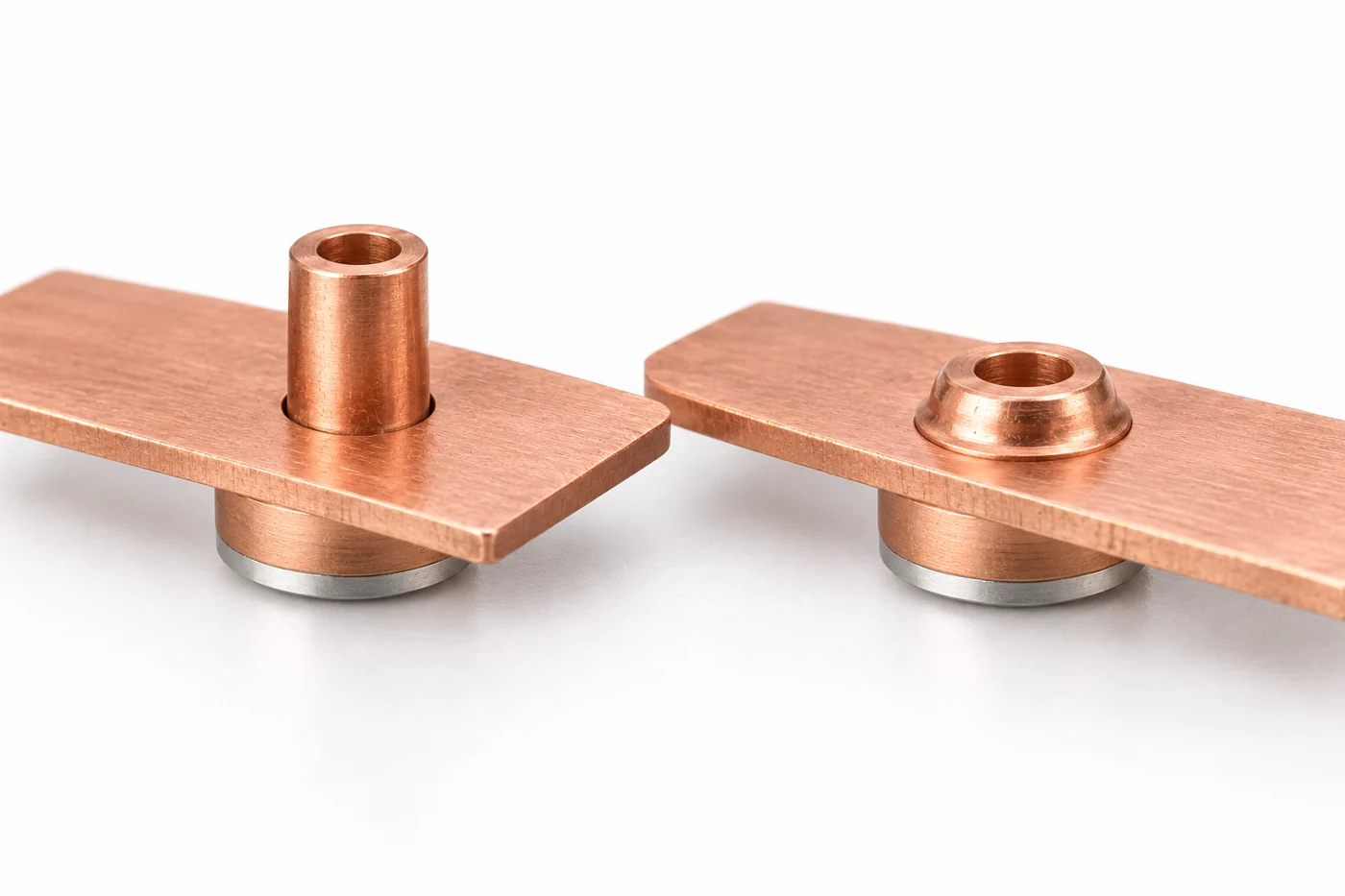
04공정 조건과 불량 분석
하중·변위와 공정 범위
공정 조건은 목표 체결부가 만들어지고 작업면과 캐리어가 유지되는 범위로 정합니다. 하중을 높이면 무조건 좋은 체결이 되는 것도 아니고, 변위를 같게 하면 항상 같은 결과가 나오는 것도 아닙니다. 소재 상태와 돌출 길이, 장비·지그의 탄성 변형이 서로 작용하기 때문입니다.
설정 변위에는 실제 끝단 변형뿐 아니라 부품 안착과 지그·장비의 휨이 포함될 수 있습니다. 따라서 장비 표시값을 완성 체결부의 압축량으로 그대로 해석하지 않습니다. 공구가 처음 닿는 기준과 최종 위치를 정의하고, 무부하 원점과 하중을 받는 조립체의 거동을 구분해야 합니다.
하중–변위 신호
하중–변위 기록은 공구 접촉, 재료 변형과 최종 다짐 과정이 매회 비슷하게 진행되는지 보여 줄 수 있습니다. 예를 들어 하중이 예상보다 일찍 증가하면 돌출량 차이, 미완전 안착, 공구 위치나 소재 상태를 확인할 근거가 됩니다. 다만 곡선 모양 하나만으로 특정 불량 원인을 확정하지 말고 치수와 단면 결과를 함께 비교합니다.
| 관리 변수 | 변화가 나타나는 위치 | 연결할 품질 항목 |
|---|---|---|
| 돌출량·중공 치수 | 초기 접촉과 변형 구간 | 체결부 외경·높이·균열 |
| 최종 변위·하중 제한 | 다짐과 종료 구간 | 유격·작업면 눌림·캐리어 휨 |
| 속도·성형 시간 | 전체 변형 이력 | 표면 상태·형상 반복성 |
| 공구 정렬·마모 | 접촉 위치와 좌우 형상 | 편심·기울기·비대칭 말림 |
| 지지 강성·안착 | 원점과 하중 전달 | 접점 높이·머리 아래 간극 |
공정 감시의 상·하한은 합격품 몇 개의 파형을 둘러싸는 방식만으로 정하지 않습니다. 의도적으로 변화시킨 치수·소재·안착 조건과 불량 시편을 비교해 어떤 신호가 기능 저하를 구분하는지 확인해야 합니다. 감시 영역이 너무 넓으면 불량을 놓치고 너무 좁으면 기능상 정상인 변동을 과도하게 배제할 수 있습니다.
조건 승인과 생산 감시
초기 검토에서는 소재 상태와 주요 치수의 변동을 포함해 조건을 비교하고, 외관·단면·유지력·저항의 결과가 함께 만족되는 구간을 찾습니다. 이후 승인된 범위에서 반복 생산을 확인하며 측정계의 반복성과 공구 마모 영향을 평가합니다. 이 과정을 거쳐야 장비 설정값이 검사 결과와 연결된 공정 조건이 됩니다.
양산 중의 하중–변위 감시는 보이지 않는 모든 균열이나 전기 성능을 직접 측정하는 검사가 아닙니다. 정기 단면, 기능 시험과 공구 점검을 연결해 감시 신호가 계속 유효한지 확인합니다. 소재 공급 상태, 공구 형상이나 캐리어 두께가 바뀌면 기존의 감시 범위를 그대로 쓰기 전에 변경 영향을 검토해야 합니다.
성형 불량과 원인 추적
끝단이 벌어졌다는 사실만으로 리벳팅이 완성된 것은 아닙니다. 원주 방향으로 고르게 성형되었는지, 머리와 캐리어가 밀착했는지, 균열과 유격이 없는지까지 확인해야 합니다. 불량 이름을 붙일 때에는 성형부뿐 아니라 작업면과 캐리어의 변화를 함께 기록합니다.
끝단 균열은 변형량이 재료가 감당할 수 있는 범위를 벗어나거나 국부 변형이 집중될 때 나타날 수 있습니다. 얇은 벽, 끝단의 흠집·버, 재료 상태와 공구 정렬을 함께 확인해야 하며 하중만 낮추는 조치가 항상 해결책은 아닙니다. 하중을 줄인 뒤 균열이 줄어도 유격이나 유지력 부족이 생기면 공정 문제는 남아 있습니다.
불량 형상과 확인 순서
| 관찰 결과 | 먼저 비교할 항목 | 추가 확인 |
|---|---|---|
| 끝단 균열 | 벽 두께·소재 상태·끝단 손상 | 단면 균열 깊이·잔여 연결부 |
| 한쪽만 벌어짐 | 중공 편심·펀치 정렬·머리 안착 | 좌우 단면·접점 기울기 |
| 벽 접힘·좌굴 | 과도한 돌출·지지 부족·공구 접촉 | 겹친 벽·체결부 내부 간극 |
| 유격·작은 체결부 | 돌출량·최종 위치·홀 치수 | 유지력·회전·머리 아래 간극 |
| 작업면 눌림 | 받침 형상·이물·과도한 성형 | 접점 높이·곡률·접점재 손상 |
| 캐리어 휨 | 지지 위치·판 두께·하중 전달 | 평면도·조립 후 접촉 위치 |
| 저항 증가 | 접합면 오염·밀착·표면 상태 | 구간별 전압 강하·온도·단면 |
비대칭 체결부는 공구 편심만으로 생기지 않습니다. 중공부의 중심이 어긋나거나 캐리어 홀의 버 때문에 접점이 기울어져도 비슷한 외관이 나타날 수 있습니다. 성형 전 단품, 안착 상태와 성형 후 단면을 같은 기준축으로 비교하면 공구 문제와 부품 문제를 나누기 쉽습니다.
벽이 접힌 형상은 외경만 재면 정상 체결부와 비슷해 보일 수 있습니다. 그러나 겹친 재료 사이의 간극과 불균일한 지지는 유지력과 전기적 안정성에 다른 영향을 줄 수 있습니다. 초기 공정 승인에서는 외관 합격품도 절단해 내부 형상이 의도대로 형성되었는지 확인하는 이유입니다.
증상을 남기는 분석
불량품을 손으로 다시 눌러 끼우거나 세척한 뒤 분석하면 최초의 간극과 잔류물 증거가 사라질 수 있습니다. 발견 상태의 사진, 발생 위치, 소재·캐리어 로트와 성형 기록을 먼저 남깁니다. 이후 비파괴 확인, 전기 측정과 필요한 파괴 분석을 순서대로 진행해야 원인과 재작업의 영향을 구분할 수 있습니다.
재리벳팅은 이미 가공 경화되고 변형된 끝단에 다시 힘을 가하는 작업입니다. 외관이 개선되어도 추가 균열이나 작업면 변형이 숨을 수 있으므로 자동으로 정상품 취급하지 않습니다. 재작업을 허용하려면 적용 범위와 횟수, 검사 및 추적 방법을 별도로 승인해야 합니다.
성형량에 따른 고정 머리 비교
INTERACTIVE 3D캐리어 위에 고르게 안착한 고정 머리의 예시입니다. 합격 여부는 승인 도면과 시험 기준으로 판정합니다.
05조립체 검사와 사용 검증
치수·단면·전기 검사
검사 계획은 성형 전 부품과 성형 후 조립체를 나누어 구성합니다. 성형 전에는 중공부와 축, 캐리어 홀을 확인하고, 성형 후에는 체결부와 머리의 자세, 캐리어 변형과 유격을 확인합니다. 최종 외경 하나만 관리하면 부품 변동과 조립 공정 변동을 구분하기 어렵습니다.
단면 검사에서는 체결부 내부의 접힘과 균열, 머리 아래 간극, 중공 바닥과 재료 경계의 변화를 볼 수 있습니다. 편심이 의심되면 절단 방향을 기록하고 서로 다른 방향의 단면을 비교합니다. 절단·연마로 생긴 눌림이나 틈을 실제 균열로 오인하지 않도록 시편 준비 상태도 함께 확인합니다.
유지력의 측정 조건
밀어내기·인장 시험에서는 어느 방향으로 접점을 밀거나 당기는지와 캐리어를 어디에 지지하는지가 결과를 바꿉니다. 시험 중 캐리어가 휘면 접점 이탈보다 판재 변형을 먼저 측정할 수 있습니다. 하중과 변위뿐 아니라 이탈·균열·캐리어 찢김 등의 파괴 위치를 기록해야 설계의 약한 부분을 구분할 수 있습니다.
회전 저항을 볼 때에는 접점이 실제로 돌기 시작한 시점과 시험 지그가 미끄러진 시점을 구분해야 합니다. 레버를 사용한다면 가한 힘과 작용 거리, 하중 방향이 토크 해석에 포함됩니다. 시험 방법과 지지 조건이 다른 수치를 그대로 비교하면 공정이 좋아졌는지 판단하기 어렵습니다.
| 검사 | 측정 기준 | 판단의 한계 |
|---|---|---|
| 외관·치수 | 기준면·접점 높이·체결부 윤곽 | 내부 균열과 저항을 단독 보증하지 않음 |
| 절단 단면 | 절단 방향·시편 준비·관찰 위치 | 한 단면이 원주 전체를 대표하지 않음 |
| 유지력·회전 | 하중 방향·지지·시험 속도·실제 파괴 | 다른 지그 결과를 직접 비교하지 않음 |
| 4선식 저항 | 전류선·검출선 위치·전류·온도 | 포함된 벌크 저항과 접합부를 구분 |
| 통전 온도 | 주위·장착·전류·안정화 조건 | 초기 저항만으로 장기 온도를 보증하지 않음 |
4선식 저항의 측정 구간
4선식 측정은 시험 전류를 흘리는 연결과 작은 전압 강하를 읽는 연결을 분리합니다. 접합부 양쪽의 전압 검출 위치를 고정하면 리드와 연결부의 영향을 줄여 작은 저항을 비교하기 쉽습니다. 그러나 검출점 사이에 접점 본체나 캐리어가 길게 포함되면 그 벌크 저항도 함께 읽으므로, 측정값 전체를 순수 접합부 저항이라고 부르지 않습니다.
시험 전류와 전압 조건은 평가 목적에 맞춰 정합니다. 작은 신호 조건의 표면막 영향을 보는 검사와 실제 통전 조건의 전압 강하·발열 검사는 서로 다른 정보를 줍니다. 시편 온도, 전류 인가 시간과 측정 순서를 고정하고, 강한 통전이 먼저 표면 상태를 바꿀 수 있다는 점도 시험 순서에 반영합니다.
저항 합격 한계는 측정 방식과 적용 회로를 떠나 하나의 값으로 정할 수 없습니다. 승인 시편의 분포, 허용 전압 강하와 온도, 열화 뒤의 기능 요구를 연결해 기준을 합의해야 합니다. 측정 반복성이 판정 폭에 비해 충분한지도 확인해야 작은 숫자의 차이를 실제 공정 차이로 해석할 수 있습니다.
완성 조립체의 검증
초기 유지력과 저항에 합격한 조립체도 사용 중에는 온도 변화, 반복 움직임과 통전의 영향을 받습니다. 하중을 받은 재료가 시간에 따라 서서히 변형하는 크리프와 변형이 구속된 상태에서 응력이 줄어드는 응력 완화는 소재·온도·유지 시간에 따라 접합부의 압력을 바꿀 수 있습니다. 접점과 캐리어의 서로 다른 열팽창, 미세 움직임과 표면막 변화도 함께 검토합니다. 필요한 검증은 실제 장착 환경과 전기·기계 하중에서 정합니다.
열 사이클이나 통전 반복 뒤에는 외관만 다시 보지 않고 저항, 유격과 접점 위치의 변화를 비교합니다. 초기값이 낮더라도 상승 추세가 계속되는 조립체는 안정적인 조립체와 다르게 취급해야 합니다. 시험 전후 온도가 다르면 저항 비교에 온도의 영향이 섞이므로 같은 기준 온도에서 비교하거나 적절한 보정을 적용합니다.
접합부 시험과 개폐 시험
리벳 접합부가 튼튼하다고 해서 작업면의 전기적 수명까지 자동으로 확보되는 것은 아닙니다. 개폐 수명은 접점재, 접촉력, 바운스, 개폐하는 부하와 아크 조건의 영향을 받습니다. 반대로 개폐 후 작업면이 심하게 손상되었어도 리벳 접합부의 상태는 별도로 평가해야 원인을 구분할 수 있습니다.
| 검증 단계 | 재현할 조건 | 전후 비교 항목 |
|---|---|---|
| 기계 기능 | 실제 지지·운동·하중 방향 | 유격·회전·높이·유지력 |
| 통전·열 | 장착·전류·주위·냉각 | 전압 강하·온도·저항 변화 |
| 환경·반복 | 사용 환경에 맞는 온도·진동·습도 | 부식·균열·접합 상태·기능 |
| 실부하 개폐 | 실제 회로·구동·개폐 시퀀스 | 작업면 손상·용착·바운스·접합부 |
| 변경 검증 | 소재·공구·치수·공정 변경 | 영향받는 기존 승인 특성 |
시험 조건에는 전류 크기뿐 아니라 통전 시간과 휴지 시간, 장착 방향과 열이 빠져나가는 경로가 포함됩니다. 캐리어를 큰 금속 지그에 고정한 시험은 실제 제품보다 열을 잘 빼앗아 온도 상승을 작게 보이게 할 수 있습니다. 시험 지그의 편의가 사용 환경을 대신하지 않도록 설치 조건과 측정 위치를 기록합니다.
판정 기준과 변경 관리
검증 전에 합격 기준과 시험 중단 조건을 정하면 좋은 결과만 골라 해석하는 일을 줄일 수 있습니다. 균열·이탈 같은 즉각적인 기능 상실과 저항·높이의 점진적 변화는 별도 항목으로 판단합니다. 시험 뒤 일부 시편을 절단해 외부 측정 변화와 내부 접합 상태를 연결하면 원인 해석이 구체적이 됩니다.
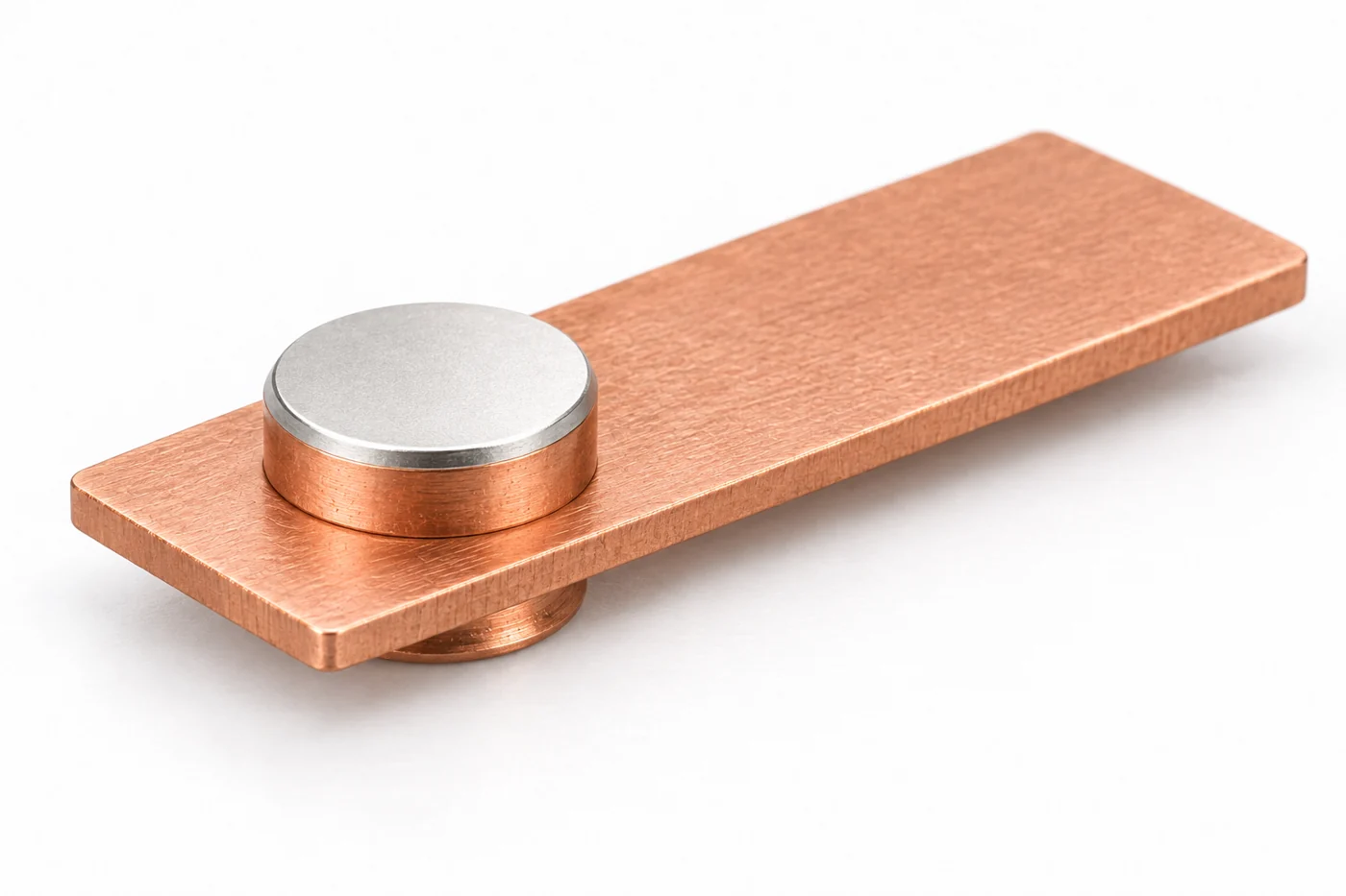
양산 검사는 승인된 공정이 유지되는지 감시하고, 설계 검증은 그 조립체가 요구 기능을 충족하는지 확인합니다. 두 역할은 연결되지만 서로 대신하지는 않습니다. 소재 상태, 중공 깊이, 공구 형상이나 표면처리 순서가 바뀌면 어떤 검증 항목에 영향을 주는지 평가하고 필요한 범위를 다시 확인합니다. 이어지는 사진은 완성품을 뒤집어 은색 작업면이 위로 보이도록 배치한 모습입니다.
06도면 사양과 제작 의뢰
도면과 검사 사양
제작 도면에는 접점 단품의 성형 전 상태와 캐리어에 리벳팅한 뒤의 상태를 구분해 표시합니다. 축 길이와 중공 깊이만으로는 완성 접점 높이, 체결부 여유 공간과 허용 유격을 알 수 없습니다. 조립도는 어떤 면을 기준으로 측정하고 어느 형상이 사용 기능을 결정하는지 보여 주어야 합니다.
작업면의 높이와 기울기는 캐리어의 실제 장착 기준에 연결합니다. 단품 머리 두께가 합격이어도 캐리어가 휘거나 머리가 덜 안착하면 상대 접점과 만나는 위치가 달라집니다. 따라서 기능에 중요한 치수는 완성 조립체에서 확인할 수 있는 기준과 측정 상태로 지정합니다.
필수 치수와 보호 영역
| 사양 묶음 | 기재할 내용 | 빠졌을 때의 문제 |
|---|---|---|
| 단품 형상 | 머리·축·중공의 치수와 단면 | 중공 깊이·관통 여부 해석 차이 |
| 재료 구성 | 접점재·축 소재·공급 상태·재료 경계 | 소재명만 같은 대체품 발생 |
| 캐리어 | 소재·두께·홀·버·안착면 | 삽입·돌출량·밀착 조건 불일치 |
| 성형 후 상태 | 체결부 윤곽·높이·기울기·유격 | 외관은 유사하나 기능이 다른 조립 |
| 작업면 보호 | 접촉 영역·허용 흠집·변형 제한 | 받침 자국과 유효면적 감소 |
| 검사·승인 | 지지·하중 방향·저항 구간·판정 | 공급자와 사용자 시험값 불일치 |
공차는 모든 치수를 똑같이 좁히는 방식보다 기능에 따라 배분하는 편이 합리적입니다. 중공 편심, 돌출 길이와 접점 높이처럼 체결과 접촉에 직접 연결되는 항목을 우선 검토합니다. 표면의 비기능 영역까지 일괄적으로 엄격하게 지정하면 검사와 공구 관리 부담이 늘어도 실제 기능 개선은 작을 수 있습니다.
복합 접점에서는 체결 뒤에도 작업면에 필요한 접점재 영역이 남는지 확인할 수 있어야 합니다. 경계의 위치와 허용 손상, 필요하면 단면 검사 방법을 사양에 연결합니다. 색상 차이나 사진 외관만으로 접점재의 실제 두께와 접합 건전성을 대신 판정하지 않습니다.
승인 기준의 공유
공급자와 사용자가 같은 시편을 측정해도 지지와 검출 위치가 다르면 다른 수치를 얻을 수 있습니다. 초기 승인 단계에서 측정 기준면, 힘을 가하는 방향과 속도, 저항 검출 위치와 온도를 맞춥니다. 합격품과 불합격품의 경계 형상을 함께 확인하면 문장만 있는 외관 기준보다 해석 차이를 줄일 수 있습니다.
도면 변경에는 단품 치수뿐 아니라 검사 방법과 공정 순서의 변경도 포함됩니다. 변경한 이유와 영향을 받는 기능, 적용 시점을 남기면 이전 승인 조건과 새 조건을 구분할 수 있습니다. 샘플을 기준으로 개발하더라도 최종 승인에는 측정 가능한 도면과 검사 사양이 필요합니다.
제작 의뢰와 비용 검토
튜블라 전기접점의 제작 의뢰는 부품 형상과 사용 기능을 함께 전달할 때 구체화됩니다. 필요한 범위가 접점 단품인지, 캐리어 포함 조립체인지, 리벳팅 조건 검토까지인지 먼저 정합니다. 이후 접점재와 축의 구성, 중공 단면과 조립 기준, 요구 검사를 연결하면 검토 대상이 분명해집니다.
견적에서 중공 구조의 이점을 소재 사용량 하나로 판단하지 않습니다. 중공부를 만드는 공정, 공구와 지그, 성형 불량의 위험, 접점재 사용량과 검사 부담이 함께 비용을 만듭니다. 끝단 성형이 쉬워져도 중공 치수 관리와 청정도 요구가 늘면 전체 비용의 변화는 달라질 수 있습니다.
비교 견적의 같은 조건
| 전달 자료 | 검토 목적 | 확인할 범위 |
|---|---|---|
| 단품도·조립도 또는 샘플 | 형상과 기능의 재구성 | 기준면·중공 단면·측정 신뢰도 |
| 소재·표면 요구 | 전기 성능과 성형성 연결 | 접점재·축 상태·마감·청정도 |
| 캐리어와 체결 정보 | 리벳팅 가능성 판단 | 홀·두께·지지·공구 접근 |
| 사용 조건 | 검증 범위 설정 | 통전·개폐·기계 하중·환경 |
| 검사와 승인 기준 | 비교 가능한 품질 범위 | 단면·유지력·저항·시험 책임 |
| 공급 범위·변경 계획 | 공정·공구·개발 범위 판단 | 단품·조립체·시제품·반복 생산 |
공법을 비교할 때에는 같은 완성 형상과 기능 기준을 사용합니다. 낮은 단품 가격에 캐리어 조립과 전기 검사가 빠져 있으면 조립체 공급 견적과 직접 비교하기 어렵습니다. 개발 공구, 초기 검증과 반복 생산의 관리 범위를 나누어 확인하면 가격 차이가 어디에서 생기는지 설명할 수 있습니다.
도면 없이 실물만 있는 경우에는 샘플의 사용 이력과 변형 여부부터 확인합니다. 이미 리벳팅된 끝단은 성형 전 길이와 구멍 깊이를 그대로 보여 주지 않으므로, 분해품 한 개에서 원래 치수를 단정하면 안 됩니다. 여러 관찰 방향과 단면, 필요한 기능을 함께 검토해 제조 가능한 기준으로 다시 정의해야 합니다.
ID METAL 제작 검토
ID METAL의 전기접점과 프레스 부품 안내를 함께 보면 접점 단품과 캐리어를 연결해 검토할 수 있습니다. 문의 시에는 공개 가능한 도면과 기능 요구, 희망 공급 범위를 정리하고 실제 적용 공정과 검사 가능 범위는 제작 협의에서 확인합니다. 특정 리벳팅 설비나 검사 항목의 적용 여부는 부품 요구를 검토한 뒤 정할 사항입니다.
제작 검토 자료는 제품문의·개발의뢰로 전달할 수 있습니다. 중공 끝단의 성형성, 작업면 보호, 캐리어 밀착과 전류 전달을 같은 조립 요구로 묶으면 필요한 도면 보완과 시제품 검증 항목을 구체적으로 정할 수 있습니다. 그 결과를 승인 기준으로 남겨야 이후 소재나 공구가 바뀌어도 같은 기능을 비교할 수 있습니다.
English Edition · Tubular Contact Riveting
A tubular electrical contact is attached to a carrier by spreading the hollow tail opposite its head. The retaining feature must be formed while preserving the working face that meets the opposing contact. Cavity dimensions, material formability, tool support and assembly conditions therefore require a combined review. Quality depends on retention, joint resistance and contact height as well as the appearance of the formed tail.
The interactive 3D shows the head supported below while the hollow tail above is spread and pressed into a retaining shape. The photographs, rotatable and zoomable sectional and forming-comparison 3D models, and chapters distinguish semi-tubular geometry from material architecture, then connect dimensions and process settings to defect analysis, inspection, qualification and manufacturing drawings.
Hollow-tail deformation
Separate the working face from the retaining feature and explain bore depth, wall thickness and protrusion.
Materials and riveting conditions
Connect material architecture, tool motion, support, force and displacement to finished-assembly quality.
From inspection to manufacturing inquiry
Translate sections, retention, resistance and service qualification into drawings and approval criteria.
01Structure and function of hollow-tail contacts
The structure of a tubular electrical contact
A tubular electrical contact is a contact component that can be attached to a carrier by riveting the hollow end of its shank. The working face on the head meets the opposing contact and carries current, while the opposite shank end forms the retaining feature that keeps the contact in the assembly. The electrical working surface and the region intentionally plastically deformed for fastening therefore require distinct design treatment within the same part.
The geometry discussed here has one head and one coaxial cylindrical shank. The bore at the shank end is blind: it terminates at a defined depth instead of passing through the head, and this article describes it as a semi-tubular contact-rivet geometry. Classification of tubular and semi-tubular parts can vary between manufacturing references. Through-bore status should therefore be established from the section and bore depth, rather than inferred from the name.
Blind and through bores
Material remains between the bore bottom and the head, preserving the electrical working face. A separate through-tube or eyelet structure requires its own review of the remaining cross-section, forming tools and current path. The geometries are not interchangeable simply because an opening is visible at the end of each.
A blind bore and a blind rivet installed by pulling from one side are different concepts. Here the contact is inserted into a preformed carrier hole and formed using support at the head and a tool at the tail. Tool access and support therefore require examination of space on both sides of the assembly.
The cavity defines where material can move during fastening. As a punch acts on the end, the cylindrical wall can spread and curl outward to produce a retaining feature wider than the carrier hole. The presence of a bore does not establish a fixed reduction in forming force or a fixed improvement in contact life. Wall thickness, material condition, protrusion and tool geometry must be considered together.
The inverted assembly orientation
In the interactive 3D, the contact head is placed below the carrier and the hollow tail points upward. A punch approaching from above forms the hollow tail, while an anvil supports the reaction at the head below. The widened feature created at the top of the model is the riveted retaining head, not the electrical working head.
The stages distinguish the part before insertion, seating in the carrier, spreading of the tail and the completed joint after tool withdrawal. The working face and contact-material boundary should remain intact through the operation; growth of the retaining head should not be achieved by crushing and changing the working face. The model illustrates the location of deformation and does not provide calculated force or stress results.
Forming the hollow rivet tail
INTERACTIVE 3DInsert the shank through the carrier hole. The lower nest supports the original contact head.
Retention and the current path
An inserted contact is retained with the carrier sheet between the original head and the newly formed retaining feature. Retaining-head diameter alone is insufficient: seating of the original head, contact with the sheet, shank tilt and residual play also matter. A visibly wide flare does not establish a stable assembly if a gap remains beneath the original head.
Service loads may act in axial tension, in-plane shear, rotation or bending. The relevant directions depend on whether the contact moves, whether the carrier acts as a spring and which loads occur during assembly. A single push-out value therefore cannot represent every aspect of retention.
Mating faces and joint interfaces
The current path can include the mating working faces, the contact body, the contact-to-carrier joint and the carrier itself. Resistance at the mating faces and resistance in the riveted joint are different measurement targets. If the resistance of the whole assembly rises, measurements over separate sections help distinguish surface contamination from a defective attachment.
Metal surfaces first meet at microscopic asperities even when they appear flat. Pressure, surface films and cleanliness affect the small areas through which current actually flows. A mechanically captive assembly can therefore have an inadequate electrical joint. Conversely, low initial resistance does not establish long-term retention or stability after thermal cycling.
| Evaluation target | Function assessed | Associated checks |
|---|---|---|
| Axial retention | Resistance to contact withdrawal | Load direction, support arrangement and failure location |
| Rotation and play | Position and orientation | Torque, tilt and gap beneath the head |
| Joint resistance | Current transfer into the carrier | Voltage-sense positions, test current and temperature |
| Working-face condition | Contact with the opposing face | Height, curvature, marks and contact-material boundary |
The link between resistance and heat
For a given section with constant resistance, doubling current produces four times the electrical loss. This relationship explains why a small joint-resistance change matters at high carrying current. Temperature rise also depends on heat removal and ambient conditions, however. Four times the calculated loss does not imply four times the temperature rise.
In practice, retention, joint resistance and working-face geometry are checked separately and then evaluated together against the same process settings. Improvement in one measure does not justify a setting that damages another function. The product photographs in this article were created to explain geometry and manufacturing principles; they are not photographs of delivered products.
02Material architecture and dimensional design
Contact materials and shank materials
Tubular describes a hollow geometry, not a contact-material composition. A hollow shank can be used in a contact made from one material or in a composite contact whose working-face material differs from its shank material. Material architecture and hollow-shank geometry should therefore be specified separately on the drawing.
In a composite contact, the contact-material layer is a metallurgically joined region at the working face. Calling it silver plating solely because it looks silver, or interpreting it as a separate washer, changes the manufacturing requirement. Plating is a separate surface-finish specification; its location and thickness must not be confused with the composite-material interface.
Electrical performance and formability
The working-face material is assessed against the actual switching conditions, including contact resistance, arc erosion, welding and material transfer. The shank and retaining feature require both current-carrying ability and sufficient formability to spread without cracking. Allocating materials to these separate roles can adjust the quantity of contact material used, but it adds requirements for interface integrity and manufacturing consistency.
Actual composite-contact product families include silver, silver-alloy or silver-metal-oxide contact material joined to a copper body. These structures place the required material at the working face and use the copper-side tail for attachment, but silver and copper colors do not identify exact composition or layer thickness. Confirm material specification and interface position from the drawing or material specification.
The same nominal material can behave differently during tail forming because of its supply condition and previous forming history. Regions hardened by cold work, heat-treatment condition and lot variation can affect forming force and cracking. A material substitution therefore requires comparison of hardness, condition and forming results with the approved part, rather than a composition match alone.
| Category | Separate drawing information | Process result to examine |
|---|---|---|
| Hollow geometry | Bore diameter, depth and wall thickness | Symmetry of spreading and deformation near the bore bottom |
| Contact material | Material specification and effective region | Working-face condition and suitability for service |
| Shank material | Material, supply condition and hardness requirements | Forming force, cracking and retained geometry |
| Composite interface | Interface location and remaining contact-material requirements | Separation, interface damage and section condition |
| Surface finish | Plating presence, coverage, thickness and cleanliness | Cracking, contamination and joint-interface condition |
Surface condition and finishing sequence
When finishing precedes forming, tool contact and large tail deformation can damage a coating or move residues into the joint. Finishing after forming requires assessment of cleaning and drying in cavities and joint gaps, retained process solution and coverage of the required regions. The preferred sequence is determined through joint resistance and cleanliness as well as appearance.
Heat treatment or lubrication may make forming easier while changing other functions. Thermal history can affect carrier spring properties and the interface in a composite contact, and lubricant residues require control at mating and joint surfaces. Managing the approved material, finish and cleaning sequence as one process specification helps establish repeatability.
Dimensions of the hollow tail and carrier
The rivetability of a tubular electrical contact cannot be determined from shank outside diameter alone. Shank length, bore diameter and depth, carrier thickness and hole size, and the seating surface beneath the head must work together. The length of tail remaining beyond the carrier is particularly important because it determines the material available to form the retaining feature.
Insufficient protrusion can leave too little material to form a retaining feature wide enough to capture the carrier. Excess protrusion can allow the wall to fold or collapse sideways before it spreads in a controlled way. The appropriate length depends on material, wall thickness, tool contact geometry and the intended formed shape; a ratio from a general rivet catalog should not be copied directly into a contact drawing.
Wall thickness and bore termination
For concentric cylindrical geometry, wall thickness is half the difference between outside and inside diameters. Both diameters can lie within their tolerances while eccentricity leaves one side thin and the other thick. Diameter checks therefore need to be accompanied by an assessment of eccentricity or minimum wall thickness when evaluating symmetrical spreading.
Blind-bore depth determines both the length of deformable wall and the material remaining below it. If the bore is too shallow, the punch may encounter resistance from the thicker region before producing the intended tail shape. Increasing depth requires a review of the remaining section toward the head, supporting stiffness and the relationship to any composite-material interface.
| Dimension or feature | Effect of variation | Verification method |
|---|---|---|
| Shank length and carrier thickness | Changes preforming protrusion | Measure the assembly with the head seated |
| Bore and outside diameters | Changes wall thickness and deformation resistance | Compare diameters, sections and minimum wall thickness |
| Bore depth and bottom profile | Changes the deformation region and remaining section | Depth measurement and section examination |
| Carrier hole and burr | Changes insertion, tilt and seating | Check hole dimensions and burr direction and height |
| Seating surface beneath the head | Changes joint gaps and alignment | Check geometry, flatness and the assembled gap |
| Formed-head diameter and height | Changes capture and surrounding clearance | Compare the formed shape with available space |
Tolerance combinations and effective clearance
Protrusion decreases when the carrier is near its maximum thickness and the shank is near its minimum length. The opposite combination increases protrusion, so a process established only with nominal prototypes may fail on production parts near tolerance limits. Calculate combinations of shank length, sheet thickness and seating gap, then verify forming with specimens close to the relevant limiting combinations.
Too little clearance between hole and shank can cause scratching or incomplete seating during insertion; too much can destabilize shank position and support of the retaining feature. Burrs, chamfers and local sheet distortion also change the actual interface. Set insertion clearance to satisfy both part dimensions and assembly function, and connect the hole-making process and measurement references to the drawing.
What changes across the formed section
INTERACTIVE 3DThe blind recess stops before the original head. The projecting tail provides material for forming.
03Manufacturing sequence and forming tools
Component manufacture and assembly sequence
Manufacturing review begins with the required supply condition as well as the finished contact geometry. Loose contacts and contacts attached to carriers require different drawings, process responsibilities and inspections. If loose contacts are riveted in a separate operation, the information linking contact manufacture to final riveting conditions must also be defined.
A contact route can be reviewed through material preparation, head and shank formation, cavity formation, any finishing and cleaning, and inspection. Whether the cavity is formed or separately machined depends on geometry, material, tool life and production conditions. Composite contacts add a contact-material joining step and interface-quality controls. Cold heading to manufacture the contact head and riveting to attach the completed contact to the carrier are different operations.
From loose parts to assemblies
Carrier manufacture establishes hole position and size, burr direction, sheet thickness and flatness. If the carrier is subsequently bent, the riveting stage must be chosen relative to bending. Riveting first changes access during later operations, while bending first can restrict contact support and punch access.
Assembly control covers orientation, insertion, head seating, carrier support and tail forming in sequence. Damage to the cavity or impact marks on the working face during feeding can change the result even with unchanged machine settings. Feeding arrangements should therefore include guides that protect the working face and tail as well as measures against incorrect orientation.
In-process cleanliness and traceability
Before riveting, examine debris around the hole and residues beneath the head. A joint formed over particles or a substantial residue film can have the correct initial height while having a different metal-to-metal interface. After cleaning, control liquid retained in the cavity and recontamination, and connect drying, storage and the interval before assembly.
Linking material, contact and carrier lots to riveting conditions makes it possible to compare where an abnormality began. Distinguishing and retaining setup specimens, stable-production specimens and specimens taken just after tool replacement also helps track changes. Traceability means preserving the links needed to reproduce a defect mechanism, rather than simply accumulating records.
Process selection considers finished-assembly yield and qualification effort alongside the speed of each operation. A shape that is easy to manufacture individually can raise total cost through feeding orientation problems or restricted assembly access. Reviewing part design and riveting together early helps reduce the risk of changing the hole or shank length after production begins.
Riveting methods and tool support
Riveting produces permanent plastic deformation by applying a tool to the contact tail. Methods include axial pressing and local forming with a tool inclined or moving along a defined path. Even when they target a similar retaining-head shape, the changing contact area, forming time and support conditions can differ.
During flaring, the tail wall bends outward while the circumference of the opening increases. Concentrated deformation at the edge can thin the wall and lead to cracking. Curling describes an end rolled into a curved retaining shape, which differs from simple flaring and flattening. The article’s 3D shows an example in which the hollow tail spreads outward and is then pressed into a retaining shape.
During axial forming, the punch lead-in and forming surface align the hollow tail and guide material outward. When the tool engages the tail broadly, axial alignment and anvil stiffness are especially important. Premature contact with the bore bottom or engagement of only one side can produce compression toward the head or asymmetric deformation instead of the intended spreading.
Differences in incremental forming
In orbital riveting, an inclined tool moves in a circular path and shifts the contact region. Radial riveting forms the material incrementally along a repeating rosette-like path; the exact motion and applicable tooling should be checked for the equipment. Radial spreading of material alone does not identify a radial riveting machine. Compare the forces and results of the two methods using the actual contact geometry, material and support conditions.
| Method | Primary review points | Results to verify |
|---|---|---|
| Axial press forming | Punch profile, concentricity and anvil stiffness | Symmetric formed head, head deformation and force–displacement |
| Orbital forming | Tool inclination, contact path and time | Tail curl, local deformation and surrounding interference |
| Radial forming | Equipment-specific motion, tool access and support | Formed geometry, tilt and repeatability |
| Common considerations | Material, protrusion, carrier and surface condition | Retention, working face and joint resistance |
Method selection begins with tool access and the deformation the carrier can tolerate. The target retaining shape, cycle and inspectability are then compared using specimens of the actual material. Sufficient machine force capacity alone does not establish that a thin contact-material layer and the carrier can be joined without damage.
Supporting the head without damaging the working face
The anvil must support the forming reaction while protecting the functional geometry of the original head. Using the same anvil for flat and curved working faces changes local pressure and can create marks or indentation. Define the support area appropriate to the head profile, tool cleanliness and the permitted marking of the contact material together.
Carrier support requires separate attention. Supporting only the contact head while leaving a thin sheet unsupported can bend the sheet during forming or change final contact height. Align the tool and anvil axes, carrier datum and contact height within one assembly reference, then evaluate residual deformation after tool withdrawal.
04Process settings and defect analysis
Force, displacement and the process window
The process window is the range that produces the intended retaining feature while preserving the working face and carrier. Higher force does not always produce a better joint, and equal travel does not always produce the same result. Material condition, protrusion and elastic deformation in the machine and fixture interact.
Indicated travel can include part seating and machine or fixture deflection as well as actual tail deformation. The displayed machine value should therefore not be interpreted directly as the compression of the finished retaining feature. Define the initial tool-contact reference and final position, and distinguish the unloaded datum from assembly behavior under load.
The force–displacement signal
A force–displacement record can show whether tool engagement, material deformation and final consolidation proceed consistently from cycle to cycle. An earlier-than-expected rise in force, for example, provides a reason to examine protrusion, incomplete seating, tool position or material condition. The curve alone should not be used to diagnose a particular defect; compare it with dimensions and section results.
| Controlled variable | Where its effect may appear | Associated quality characteristic |
|---|---|---|
| Protrusion and cavity dimensions | Initial contact and deformation region | Formed-head diameter, height and cracking |
| Final travel and force limit | Consolidation and termination | Play, working-face indentation and carrier bending |
| Speed and forming time | Overall deformation history | Surface condition and geometric repeatability |
| Tool alignment and wear | Contact position and side-to-side geometry | Eccentricity, tilt and asymmetric curling |
| Support stiffness and seating | Datum and force transfer | Contact height and gap beneath the head |
Monitoring limits should not be set only by drawing an envelope around a few acceptable traces. Compare deliberate variations in dimensions, material and seating with defective specimens to determine which signals distinguish functional deterioration. Limits that are too broad can miss defects, while limits that are too narrow can reject variation that remains functionally acceptable.
Process approval and production monitoring
Initial review compares settings across material condition and key dimensional variation to find a region satisfying appearance, sections, retention and resistance together. Repeated production within that region then establishes measurement repeatability and the influence of tool wear. This connects machine settings to verified quality results.
Production force–displacement monitoring does not directly measure every hidden crack or electrical property. Link it to periodic sectioning, functional tests and tool inspection to confirm that the signal remains meaningful. Changes in material supply condition, tool geometry or carrier thickness require an impact review before existing monitoring limits are reused.
Forming defects and cause tracing
Spreading the tail does not by itself complete a sound riveted joint. The review must cover circumferential uniformity, seating of the head against the carrier, cracking and play. Defect records should include changes in the working face and carrier as well as the formed tail.
Tail cracking can occur when deformation exceeds the material’s capacity or becomes locally concentrated. Thin walls, end damage or burrs, material condition and tool alignment should be reviewed together; reducing force is not always a sufficient remedy. If lower force reduces cracking but introduces play or inadequate retention, the process problem remains.
Defect shapes and the review sequence
| Observation | First comparison | Further checks |
|---|---|---|
| Tail cracking | Wall thickness, material condition and end damage | Crack depth in section and remaining connected material |
| One-sided spreading | Bore eccentricity, punch alignment and head seating | Sections on both sides and contact tilt |
| Wall folding or buckling | Excess protrusion, inadequate support and tool engagement | Folded walls and internal gaps |
| Play or a small formed head | Protrusion, final position and hole size | Retention, rotation and gap beneath the head |
| Working-face indentation | Anvil profile, debris and excessive forming | Contact height, curvature and contact-material damage |
| Carrier bending | Support location, sheet thickness and force transfer | Flatness and assembled contact position |
| Increased resistance | Joint contamination, seating and surface condition | Section voltage drops, temperature and cross-section |
An asymmetric retaining feature is not caused only by tool misalignment. Bore eccentricity or contact tilt caused by a carrier-hole burr can produce a similar appearance. Comparing the loose part, seated assembly and finished section against the same datum axis helps distinguish tooling from component causes.
A folded wall can produce an outside diameter resembling that of a satisfactory retaining feature. Gaps between folded layers and nonuniform support can nevertheless change retention and electrical stability. This is why initial process approval should include sections of parts that pass external visual inspection.
Analysis that preserves the evidence
Repressing a defective part by hand or cleaning it before examination can remove evidence of the original gap or residue. First preserve photographs of the as-found condition, the location of discovery, material and carrier lots, and forming records. Proceed through nondestructive checks, electrical measurement and any required destructive analysis so that original causes can be distinguished from rework effects.
Reriveting applies force to a tail that has already deformed and work-hardened. Improved appearance can conceal additional cracking or working-face deformation, so a reworked part should not automatically be treated as equivalent to a normal part. Any permitted rework requires separately approved scope, number of operations, inspection and traceability.
Compare the amount of tail forming
INTERACTIVE 3DAn example of a retaining head seated evenly above the carrier. Acceptance follows the approved drawing and test criteria.
05Assembly inspection and service qualification
Dimensional, section and electrical inspection
The inspection plan separates parts before forming from assemblies after forming. Before forming, check the cavity, shank and carrier hole; afterward, check the retaining feature, head orientation, carrier deformation and play. Controlling only one final outside diameter makes it difficult to distinguish component variation from assembly-process variation.
Sectioning can reveal internal folds and cracks, gaps beneath the head, and changes at the bore bottom or material interface. Where eccentricity is suspected, record the section orientation and compare sections in different directions. Examine specimen preparation as well, so that cutting or polishing damage is not mistaken for a service or forming crack.
Conditions for retention measurements
Push-out and pull tests depend on the direction of loading and where the carrier is supported. If the carrier bends during testing, the measurement may characterize sheet deformation before contact withdrawal. Record the failure location—such as withdrawal, cracking or carrier tearing—alongside force and displacement to identify the weak part of the design.
When evaluating rotational resistance, distinguish actual contact rotation from slip in the test fixture. With a lever arrangement, force, lever arm and load direction all enter the torque interpretation. Values from different methods or support conditions cannot be compared directly to judge process improvement.
| Inspection | Measurement reference | Interpretation limit |
|---|---|---|
| Visual and dimensional | Datums, contact height and formed outline | Does not alone establish internal integrity or resistance |
| Cross-section | Section direction, preparation and observation position | One section does not represent the entire circumference |
| Retention and rotation | Load direction, support, test speed and actual failure | Do not directly compare different fixture arrangements |
| Four-wire resistance | Current and sense positions, current and temperature | Separate included bulk resistance from the joint contribution |
| Temperature under current | Ambient, mounting, current and stabilization | Initial resistance alone does not establish long-term temperature |
The measurement section in a four-wire test
A four-wire measurement separates the connections carrying test current from those sensing the small voltage drop. Fixing voltage-sense positions on each side of the joint reduces lead and connection effects when comparing small resistances. If a substantial length of contact body or carrier lies between the sense points, its bulk resistance is included. The entire reading should not then be called pure joint resistance.
Test current and voltage are selected for the evaluation purpose. A low-level test examining surface-film effects provides different information from voltage-drop and heating measurements at service current. Fix specimen temperature, current-application time and measurement order, and account for the possibility that a preceding high-current test changes the surface condition.
A resistance acceptance limit cannot be defined as one value independent of measurement method and circuit. Agree the criterion by linking approved-specimen distributions, permissible voltage drop and temperature, and functional requirements after aging. Measurement repeatability must also be adequate relative to the decision band before small numerical differences are interpreted as real process differences.
Qualification of the finished assembly
An assembly passing initial retention and resistance checks still experiences temperature changes, repeated motion and current in service. Creep, time-dependent deformation under load, and stress relaxation, a reduction of stress under constrained strain, can alter pressure in the joint depending on material, temperature and exposure time. Differential thermal expansion, small relative movements and surface-film changes also require consideration. Qualification requirements come from the actual mounting environment and electrical and mechanical loads.
After thermal or current cycling, compare changes in resistance, play and contact position as well as appearance. An assembly whose resistance continues to rise requires different consideration from one that remains stable, even if its initial value was low. Compare resistance at the same reference temperature or apply an appropriate correction so that temperature differences do not obscure the result.
Joint tests and switching tests
A strong riveted joint does not automatically establish electrical endurance at the working face. Switching life depends on contact material, contact force, bounce, switched load and arcing conditions. Conversely, severe working-face damage after switching still requires a separate examination of the riveted joint to distinguish causes.
| Qualification stage | Conditions to reproduce | Before-and-after comparison |
|---|---|---|
| Mechanical function | Actual support, motion and load directions | Play, rotation, height and retention |
| Current and heat | Mounting, current, ambient and cooling | Voltage drop, temperature and resistance change |
| Environment and repetition | Temperature, vibration and humidity relevant to service | Corrosion, cracking, joint condition and function |
| Actual-load switching | Actual circuit, drive and switching sequence | Face damage, welding, bounce and joint condition |
| Change qualification | Material, tool, dimension and process changes | Previously approved characteristics affected by the change |
Test conditions include current duration and rest periods, mounting orientation and heat-removal paths as well as current magnitude. A carrier clamped to a large metal fixture may lose heat more effectively than in the product and show a smaller temperature rise. Record installation conditions and measurement positions so that fixture convenience does not substitute for the service environment.
Acceptance criteria and change control
Defining acceptance and test-stop criteria before qualification reduces selective interpretation of favorable results. Immediate functional failures such as cracking or withdrawal should be assessed separately from gradual changes in resistance or height. Sectioning selected specimens afterward connects external measurement changes with the internal joint condition.
Production inspection monitors whether the approved process remains controlled; design qualification establishes whether the assembly fulfills its required function. The two are connected but do not replace each other. When material condition, bore depth, tool geometry or finishing sequence changes, assess which qualification characteristics are affected and repeat the relevant verification. The following photograph shows the completed assembly turned over so that the silver-colored working face points upward.
06Drawing specifications and manufacturing inquiries
Drawings and inspection specifications
Manufacturing drawings should distinguish the contact before forming from the contact after riveting to the carrier. Shank length and bore depth alone do not define final contact height, space for the retaining feature or permissible play. The assembly drawing should identify measurement datums and the features that determine service function.
Working-face height and tilt should be related to the carrier’s actual mounting datum. Even with acceptable loose-part head thickness, carrier bending or incomplete seating can change where the opposing contact is met. Functionally important dimensions should therefore be specified with datums and measurement conditions usable on the finished assembly.
Essential dimensions and protected regions
| Specification group | Information to include | Problem if omitted |
|---|---|---|
| Loose-part geometry | Head, shank and cavity dimensions and section | Different interpretations of depth and through status |
| Material architecture | Contact and shank materials, supply condition and interface | Substitutes sharing only a nominal material name |
| Carrier | Material, thickness, hole, burr and seating surface | Inconsistent insertion, protrusion and seating |
| As-formed condition | Retaining outline, height, tilt and play | Assemblies with similar appearance but different function |
| Working-face protection | Contact region and permissible marks and deformation | Anvil marks and reduced effective working area |
| Inspection and approval | Support, load direction, resistance section and acceptance | Supplier and user results that do not agree |
Tolerances are better allocated by function than tightened equally on every dimension. Review features directly linked to riveting and contact function first, such as cavity eccentricity, protrusion and contact height. Applying uniformly strict requirements to nonfunctional surface regions can increase inspection and tool-control effort with little functional benefit.
For a composite contact, the specification should permit verification that the required contact-material region remains at the working face after riveting. Connect interface location, permissible damage and, where required, sectioning methods to the specification. Color differences or photographic appearance should not replace evaluation of actual contact-material thickness and interface integrity.
Shared approval criteria
A supplier and user can obtain different values from the same specimen when support and sensing positions differ. During initial approval, align datum surfaces, loading direction and speed, resistance-sense locations and temperature. Reviewing boundary examples of acceptable and unacceptable shapes together reduces interpretation differences compared with written appearance criteria alone.
Drawing changes should cover inspection methods and process sequence as well as part dimensions. Recording the reason, affected functions and implementation point distinguishes the previous approval from the new condition. Even when development begins from a physical sample, final approval requires measurable drawings and inspection specifications.
Manufacturing inquiries and cost review
A tubular electrical-contact inquiry becomes specific when part geometry and service function are supplied together. First define whether the scope is loose contacts, carrier assemblies or a review of riveting conditions as well. Then connect the contact and shank materials, cavity section, assembly references and required inspections to make the review scope clear.
The value of a hollow structure should not be judged from material usage alone. Cavity manufacture, tooling and fixtures, forming-defect risk, contact-material quantity and inspection effort all contribute to cost. Even if tail forming becomes easier, tighter cavity control and cleanliness requirements can change the total cost outcome.
Comparable quotation conditions
| Information supplied | Review purpose | Scope to establish |
|---|---|---|
| Part and assembly drawings or a sample | Reconstruct geometry and function | Datums, cavity section and measurement confidence |
| Material and surface requirements | Connect electrical behavior and formability | Contact material, shank condition, finish and cleanliness |
| Carrier and fastening information | Assess rivetability | Hole, thickness, support and tool access |
| Service conditions | Define qualification scope | Carrying and switching current, mechanical loads and environment |
| Inspection and approval criteria | Establish comparable quality requirements | Sections, retention, resistance and test responsibilities |
| Supply scope and change plans | Define process, tooling and development work | Loose parts, assemblies, prototypes and repeat production |
Compare processes against the same final geometry and functional criteria. A low loose-part price excluding carrier assembly and electrical inspection is not directly comparable with an assembly-supply quotation. Separating development tooling, initial qualification and repeat-production controls makes the source of a price difference understandable.
When only a physical sample is available, first establish its service history and whether it has deformed. A riveted tail does not directly reveal the original shank length or bore depth, so original dimensions should not be inferred conclusively from one disassembled part. Use multiple views, sections and required functions to reconstruct a manufacturable specification.
Manufacturing review with ID METAL
ID METAL’s electrical-contact and pressed-component pages provide a starting point for reviewing the contact and carrier together. An inquiry should identify drawings cleared for sharing, functional requirements and the desired supply scope; the applicable process and inspection scope are confirmed during manufacturing review. The use of particular riveting equipment or inspection items is determined after the part requirements are examined.
Manufacturing-review information can be submitted through product inquiries and development requests. Treating hollow-tail formability, working-face protection, carrier seating and current transfer as one assembly requirement makes drawing revisions and prototype-verification tasks specific. Recording the results as approval criteria allows the same functions to be compared when materials or tools subsequently change.
추가 정보
검색엔진용 요약
튜블라 전기접점은 머리 반대쪽의 중공 끝단을 벌려 캐리어에 고정하며, 접촉 작업면과 체결부의 기능을 나누어 설계합니다. 중공 깊이·벽 두께·돌출량과 소재 상태, 공구 지지·하중·변위를 함께 관리하고, 완성 조립체의 유지력·저항·접점 위치를 검사한 뒤 실제 통전·환경 조건으로 검증해야 합니다.
핵심 포인트 정리
- 튜블라는 중공 형상이며, 복합 접점재 구성과 표면 도금은 별도 사양입니다.
- 명칭만으로 관통 여부를 판단하지 않고 단면과 중공 깊이를 확인합니다.
- 중공 끝단을 성형하는 동안 기존 머리의 작업면과 캐리어를 보호합니다.
- 돌출량·벽 두께·편심·소재 상태와 공구 지지를 함께 검토합니다.
- 유지력·회전·접합부 저항은 서로 다른 기능이며 시험 조건을 고정해야 합니다.
- 양산 감시와 사용 조건 검증을 연결하고 소재·공구·공정 변경을 관리합니다.
FAQ
튜블라 전기접점은 속이 끝까지 뚫려 있나요?
이 글의 대상은 축 끝의 구멍이 일정 깊이에서 끝나고 접점 머리까지 관통하지 않는 반중공 형상입니다. 튜블라와 세미튜블라의 명칭은 제조 자료마다 분류가 다를 수 있으므로 단면과 구멍 깊이, 머리 쪽 잔여 단면으로 실제 구조를 확인해야 합니다.
리벳팅할 때 어느 부분이 변형되나요?
캐리어 밖으로 나온 중공 끝단을 바깥으로 벌리거나 공구 형상에 따라 말아 체결부를 만듭니다. 전류를 연결하는 기존 머리의 작업면은 보호해야 합니다. 본문의 3D는 머리를 아래에서 받치고 위쪽 끝단을 벌려 눌러 고정하는 방향으로 보여 줍니다.
튜블라와 복합 접점, 은도금은 같은 의미인가요?
튜블라는 축의 중공 형상이고, 복합 접점은 작업면 재료와 몸체 재료의 구성입니다. 은도금은 별도의 표면처리 사양입니다. 복합 접점에도 중공 축을 적용할 수 있으며 세 항목은 도면에서 각각 지정해야 합니다.
리벳팅 하중과 돌출 길이는 어떻게 정하나요?
실제 소재 상태, 중공 내·외경과 깊이, 캐리어 두께와 홀, 공구 형상과 지지를 함께 검토합니다. 치수 한계 조합의 시편에서 체결부 형상·유지력·저항·작업면 변화를 확인해 공정 범위를 정합니다. 일반 리벳의 비율이나 장비 하중을 접점의 공통 조건으로 적용하지 않습니다.
끝단이 넓게 퍼졌으면 합격인가요?
외경만으로는 머리 아래 간극, 내부 접힘·균열과 접합부 저항을 판단할 수 없습니다. 체결부의 대칭성과 높이, 접점 기울기와 캐리어 변형을 보고 필요한 단면·유지력·전기 검사와 연결해야 합니다.
유지력이 좋으면 전기저항도 낮은가요?
유지력과 전기적 접합 상태는 다른 기능입니다. 금속 표면막과 실제 접촉 영역이 저항에 영향을 주므로 유지력이 좋아도 저항을 별도로 확인합니다. 4선식 측정에서는 검출 위치와 온도를 고정하고 접점·캐리어의 벌크 저항이 포함되는 범위를 구분합니다.
제작 검토에 필요한 자료는 무엇인가요?
단품도와 조립도 또는 샘플, 소재·표면 요구, 캐리어 홀과 두께, 사용 조건과 검사 기준을 준비합니다. 단품 또는 조립체 공급 범위와 변경 계획도 함께 정리합니다. 샘플에서 출발하더라도 성형 전 치수와 완성 조립체의 기능 기준은 별도로 재구성해야 합니다.
관련 주제 확장 설명
중공 치수와 공차 누적
축 길이와 캐리어 두께의 조합이 실제 돌출량을 바꿉니다. 중공의 편심은 같은 지름에서도 최소 벽 두께를 달라지게 하므로, 평균 치수뿐 아니라 조립 한계 조건의 형상과 성형 결과를 함께 확인해야 합니다.
작업면 보호와 캐리어 지지
받침은 성형 반력을 전달하면서 접점 작업면의 곡률과 높이를 유지해야 합니다. 캐리어의 지지 위치와 홀의 버까지 함께 검토하면 작업면 눌림, 접점 기울기와 판재 휨의 원인을 구분하기 쉽습니다.
공정 감시와 장기 안정성
하중–변위 감시는 반복 생산의 이상을 찾는 수단입니다. 단면과 기능 결과에 연결한 판정 범위를 사용하고, 통전·온도·환경 노출 전후의 저항과 유지 기능을 비교해 초기 합격 이후의 변화를 확인해야 합니다.
내부 링크
재료 구성과 표면 마감의 구분은 전기접점 도금 선택, 전기적 손상은 접점 용착과 발열에서 이어서 살펴볼 수 있습니다. 캐리어 홀의 버와 절단 상태는 프레스 금형 클리어런스와 절단 품질과 연결해 검토합니다.
부품과 공급 범위는 전기접점 및 프레스 부품 안내를 바탕으로 정리할 수 있습니다. 품질방침과 요구 검사 범위를 함께 확인하고, 도면·소재·조립 조건은 제품문의·개발의뢰로 전달해 주세요.