
프레스 금형 클리어런스:
절단면·버·금형 수명 관리 기준
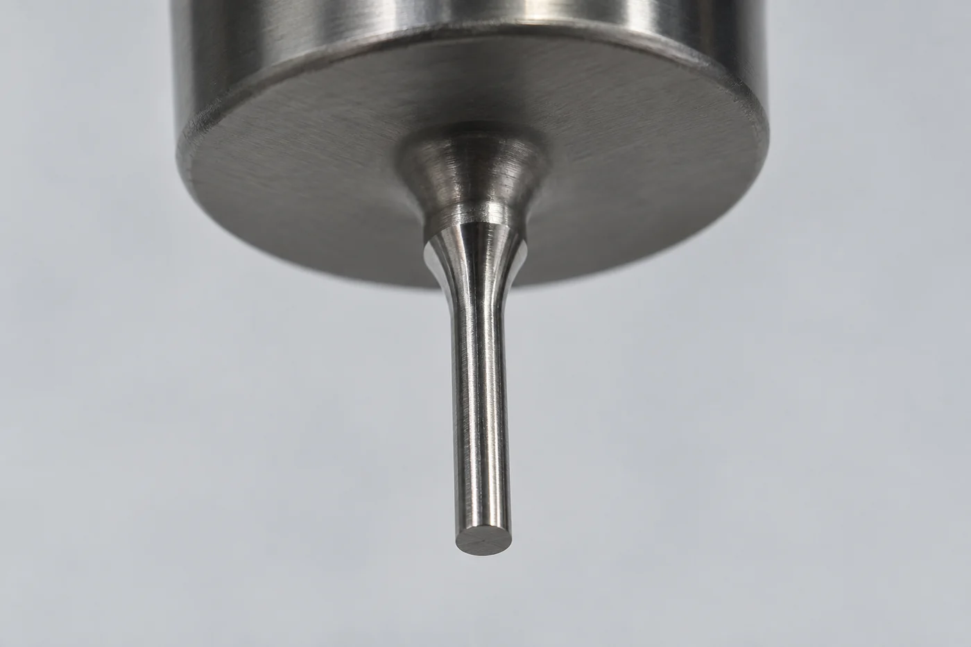
프레스 금형 클리어런스는 펀치와 다이 절삭날 사이의 간극입니다. 소재가 변형되고 분리되는 경로를 바꾸므로 절단면·버·치수뿐 아니라 금형 하중과 후속 성형의 균열에도 영향을 줍니다.
적정 간극은 제품 기능과 반복 생산을 함께 만족하는 운전 범위입니다. 같은 소재와 두께도 형상·날 상태·정렬에 따라 결과가 달라집니다. 버가 높다는 이유만으로 간극을 줄이거나 프레스 톤수를 높이기 전에, 어느 위치에서 무엇이 달라졌는지 확인해야 합니다.
기준부터 통일
편측·양측 표기를 구분하고, 간극 길이와 실제 판 두께를 함께 기록합니다.
기능으로 판단
매끈한 전단면의 길이만 보지 않습니다. 버·치수·하중과 다음 공정의 결과를 함께 비교합니다.
수명 범위로 승인
새 날의 첫 제품부터 재연마 직전까지 검토합니다. 도면 치수·버 방향·후속 변형·마모를 연결합니다.
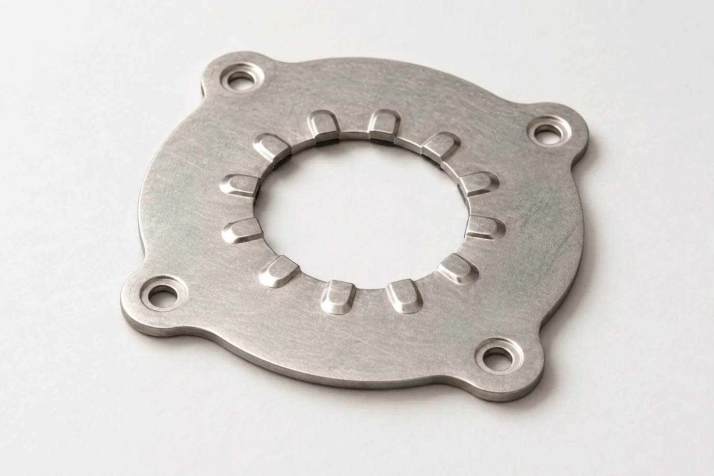
01간극 정의와 절단면
편측·양측 클리어런스와 계산 기준
원형 피어싱의 양측 클리어런스는 다이 지름에서 펀치 지름을 뺀 값입니다. 이 값의 절반이 반경 방향 한쪽의 간극, 즉 편측 클리어런스입니다.
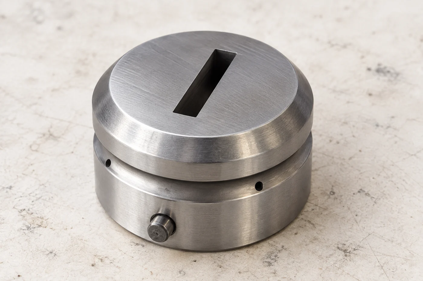
비율을 비교하기 전에 편측·양측을 맞춥니다
‘클리어런스 10%’가 편측 기준이면 한쪽 간극은 판 두께의 10%입니다. 양측 합계 기준이면 한쪽은 5%이므로 실제 간극이 두 배 차이 납니다. 제조사 선정표와 금형 도면을 비교할 때 먼저 이 정의를 확인합니다.
비원형 윤곽에서는 대응하는 절삭날 사이의 국부 간극을 윤곽에 수직한 방향으로 확인합니다. 외접원의 지름 차이로 대신할 수 없습니다.
| 구분 | 계산 기준 | 계산 예 |
|---|---|---|
| 판 두께 | 클리어런스 비율의 기준 | 1.00 mm |
| 펀치·다이 지름 | 원형 피어싱 절삭날 치수 | 펀치 10.00 mm · 다이 10.16 mm |
| 양측 클리어런스 | 다이 지름 − 펀치 지름 | 0.16 mm · 판 두께의 16% |
| 편측 클리어런스 | 지름 차이 ÷ 2 | 0.08 mm = 80 μm · 판 두께의 8% |
실제 두께와 조립 상태까지 기록합니다
표의 숫자는 표기와 단위를 설명하는 계산 예이며, 특정 소재의 권장 간극이 아닙니다. 같은 금형에 두께 0.95 mm와 1.05 mm 판을 넣으면 편측 간극은 0.08 mm로 같지만 비율은 각각 약 8.42%와 7.62%가 됩니다. 공칭 두께만 기록하면 투입 소재의 차이를 놓칠 수 있습니다.
설계 간극과 운전 중 실제 간극도 구분합니다. 제작 공차, 날 마모·소재 부착, 조립 정렬과 가압 중 변형이 국부 간극을 바꿉니다. 펀치와 다이가 각각 도면 치수에 맞아도 조립된 윤곽 전체의 간극이 균일하다는 뜻은 아닙니다.
‘편측 0.08 mm, 기준 두께 1.00 mm, 8%’처럼 길이와 비율을 함께 남깁니다. 펀치·다이의 측정 위치와 측정일, 재연마 상태를 연결하면 수정 전후를 같은 기준으로 비교할 수 있습니다.
절단면 네 영역과 균열 경로
일반 타발에서는 펀치 접촉 후 탄성 변형이 일어나고, 하중이 커지면 절삭날 주변이 소성 변형합니다. 이어 펀치와 다이 쪽에서 발생한 균열이 연결되며 제품과 스크랩이 분리됩니다.
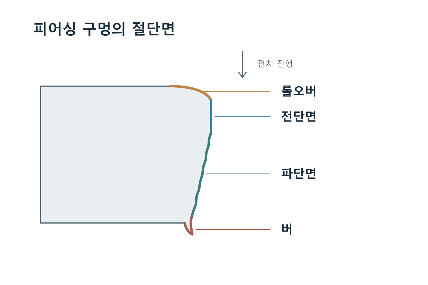
관찰 대상과 펀치 방향부터 표시합니다
- 다이 롤·롤오버: 피어싱 후 남은 판재의 구멍에서 펀치 진입면이 둥글게 처진 부분입니다.
- 전단면: 그 아래의 비교적 매끈한 부분입니다.
- 파단면: 균열 전파로 형성된 부분입니다.
- 버: 펀치 출구 쪽에서 판 표면 밖으로 돌출된 부분입니다.
위 순서는 피어싱 후 남은 판재를 펀치 진입면부터 읽는 기준입니다. 분리된 슬러그나 블랭킹 제품의 외곽에서는 방향이 반대입니다. 관찰 대상과 펀치 방향을 표시해야 같은 사진을 거꾸로 해석하지 않습니다.
롤오버는 모서리가 눌리며 소재가 흐른 결과입니다. 파단면의 기울기는 두 절삭날에서 시작된 변형과 균열 경로를 반영합니다. 따라서 구멍 입구·출구의 지름이 다르거나 외곽이 두께 방향으로 기울어질 수 있으며, 실제 조립에 쓰이는 구간에 따라 기능도 달라집니다.
전단면 길이와 광택만으로 판정하지 않습니다
전단면이 길다고 절단 품질 전체가 좋은 것은 아닙니다. 균열이 적절히 연결되지 않으면 2차 전단으로 두 번째 매끈한 띠가 생길 수 있습니다. 이를 좋은 전단면으로 판단하면 추가 하중과 국부 변형을 놓칩니다.
버는 원래 판 표면 밖으로 나온 높이뿐 아니라 뿌리 형상과 연속성도 확인합니다. 길고 얇은 버와 짧고 단단한 버는 손상·탈락 위험과 제거 방법이 다를 수 있습니다. 정면 사진과 함께 측면 관찰 및 필요한 위치의 단면을 확인합니다.
사진의 명암은 조명과 반사각에도 영향을 받습니다. 현미경으로 전단면·파단면 경계를 확인하고 표면 형상 측정이나 단면과 대조합니다. 이렇게 확인한 절단면을 생산 이력과 연결하면 금형 상태를 진단하는 자료가 됩니다.
02품질 진단과 선정 조건
간극 과소·과대와 버의 진단
버가 높다는 사실만으로 간극이 크거나 작다고 판정할 수는 없습니다. 절단면 형상과 하중, 버가 생긴 위치를 함께 확인해야 원인을 좁힐 수 있습니다.
작은 간극과 큰 간극의 경향을 구분합니다
작은 간극은 절삭날 사이 소재의 구속과 균열 연결 방식을 바꿉니다. 조건에 따라 2차 전단과 강한 마찰이 생겨 타발력·스트리핑력이 커질 수 있습니다. 긴 전단면과 함께 펀치 측면의 마찰 흔적과 국부 마모를 확인합니다.
큰 간극에서는 소재가 더 쉽게 휘고 회전합니다. 롤오버, 파단면 기울기와 입구·출구 치수 차이가 늘어날 수 있고, 지나치면 큰 버와 불안정한 절단면이 생길 수 있습니다. 다만 간극이 커질수록 버도 계속 커진다는 관계를 모든 소재에 적용할 수는 없습니다.
Dayton의 고속 피어싱 자료는 공정에 맞게 간극을 넓힌 특정 영역에서 버와 후퇴 마찰에 따른 마모가 줄어들 수 있다고 설명합니다. 이 이점을 사용하려면 구멍 치수, 롤오버, 파단면 경사와 슬러그 상승을 함께 제어해야 합니다. 큰 간극 자체를 권장하는 설명은 아닙니다.
발생 위치와 날 상태로 원인을 확인합니다
| 관찰 결과 | 검토할 원인 | 다음 확인 |
|---|---|---|
| 두 번째 전단 띠 · 높은 복귀 하중 | 작은 간극 · 강한 마찰 · 소재 부착 | 단면의 2차 전단 · 펀치 측면 · 실제 간극 |
| 큰 롤오버 · 기울어진 파단면 | 큰 간극 · 지지 부족 · 변형 | 윤곽별 입구·출구 치수 · 홀드다운 상태 |
| 둘레 한쪽에 집중된 버 | 편심 · 정렬·가이드 문제 · 국부 날 손상 | 둘레 방향 버 지도 · 조립·가압 상태의 정렬 |
| 생산 후 버·긁힘 증가 | 마모 · 치핑 · 응착 · 윤활 변화 | 날 상태 · 생산수 · 소재 로트 · 윤활 이력 |
| 외관은 양호하나 후속 성형 균열 | 전단 영향부의 가공경화·미세 손상 | 실제 버 방향의 성형 시험 · 단면 관찰 |
비교 시험에서는 날 상태와 윤활을 맞추고 같은 위치를 같은 방법으로 측정합니다. 새 날과 마모된 날의 결과를 섞으면 간극 효과를 잘못 읽기 쉽습니다. 날끝의 둥글어짐과 미세 치핑도 국부 변형과 버 형성을 바꿉니다.
한쪽 버가 높으면 평균 간극만 바꾸지 말고 둘레 분포를 확인합니다. 한쪽은 좁고 반대쪽은 넓은 상태에서 다이 전체를 확대하면 양쪽 증상이 다르게 변합니다. 원형 구멍은 여러 둘레 방향을, 슬롯은 양 측면과 양 끝을 따로 비교합니다.
수정은 원인 가설과 확인 결과를 연결해 진행합니다. 반복되는 높은 버 위치에서 날 치핑이 확인되면, 먼저 손상 원인을 조사하고 날 상태를 복원합니다. 수정 뒤에는 버와 함께 치수·하중·다음 공정 결과를 다시 비교합니다.
소재·두께·형상별 간극 검토
재질명만으로 최종 간극을 정할 수는 없습니다. 소재 공급 상태와 실제 두께, 제품 윤곽, 공구 구조 및 후속 기능을 함께 검토합니다.
제조사 수치는 적용 조건과 함께 읽습니다
같은 합금도 열처리·조질·냉간가공 정도에 따라 강도와 연성이 달라집니다. 성적서의 강도 범위, 경도 또는 공급 상태를 실제 투입 두께와 연결해 기록해야 소재 변경 후 결과를 설명할 수 있습니다.
연성이 큰 소재는 분리 전 변형량이 커 롤오버와 전단면 형성이 달라질 수 있습니다. 고강도 소재는 날에 더 큰 응력·충격을 주며, 조직과 국부 연성은 절단 후 균열 민감도에 영향을 줍니다. 알루미늄과 일부 스테인리스 등에서 생길 수 있는 소재 부착도 유효 날 형상과 마찰을 바꾸므로 재질별 윤활·공구 대책을 검토합니다.
MISUMI는 연강 SPC의 직선·완만한 곡선에서 수명을 고려한 편측 간극 약 6~8%, 전단면 길이 약 30%를 설명합니다. 이는 모든 소재·형상의 합격기준이 아닙니다. 같은 자료에서도 코너의 소재 유동 차이가 전단면과 마모를 바꿀 수 있다고 설명합니다. 제조사 표는 소재·두께·금형 계열·품질 목표를 확인한 뒤 시험의 출발조건으로 사용합니다.
작은 구멍과 코너는 별도로 검토합니다
- 작은 구멍: 구멍 지름과 판 두께의 비를 확인합니다. 같은 편측 간극에서도 가는 펀치는 단면과 측면 지지가 작아 좌굴·파손·복귀 저항을 세밀하게 검토해야 합니다. 외곽의 조건을 그대로 적용하지 않습니다.
- 슬롯 끝·내측 코너·좁은 연결부: 변형 집중과 절삭날의 국부 강성을 확인합니다. 직선부에서 양호한 조건도 이 부위에는 맞지 않을 수 있으므로 날끝 반경, 코너 형상, 주변 스크랩 폭과 소재 지지 면적을 함께 봅니다.
압연 방향과 절단선 방향의 관계도 기록합니다. 소재의 방향성이 크거나 다음 공정에서 가장자리를 늘린다면, 방향이 다른 시편을 섞어 비교할 때 변동 원인을 놓칠 수 있습니다. 코일 폭·길이 방향의 채취 위치까지 남기면 로트 비교가 명확해집니다.
한 제품에서도 주요 구멍, 외곽과 작은 코너의 품질 요구는 다를 수 있습니다. 필요한 기능에 따라 공정을 나누거나 별도 마무리 가공을 적용하는 편이 합리적일 수 있습니다.
03기능 요구와 도면 기준
절단면 기능과 후속 성형성
절단면 평가는 그 면이 실제로 하는 일에서 출발합니다. 단순 외곽, 핀 맞춤 구멍, 밀봉면 가까운 모서리와 늘림 성형할 플랜지 가장자리는 요구가 다릅니다.
버를 제거해도 성형 손상은 남을 수 있습니다
기능에 따라 전단면 비율, 버 높이와 입구 지름의 우선순위를 정합니다. 핀 맞춤 구멍에서는 확장률보다 유효 접촉 길이, 진원도와 두께 방향 형상이 중요할 수 있습니다. 반대로 크게 늘리는 가장자리에는 매끈한 띠가 짧더라도 손상이 작은 절단 조건이 유리할 수 있습니다.
후속 성형에서는 눈에 보이는 버 외에 가공경화와 미세 손상을 확인합니다. 전단 영향부는 절단 중 이미 큰 소성 변형을 받아, 다시 늘릴 때 균열 시작점이 될 수 있습니다. 버 제거 후에도 내부 손상이 남을 수 있으므로 디버링만으로 성형성이 회복된다고 단정하지 않습니다.
드로잉 불량과 성형 조건을 함께 검토하면 소재 유입 문제와 절단 가장자리 문제를 구분하는 데 도움이 됩니다.
구멍 확장률은 시험 조건과 함께 해석합니다
구멍 확장 시험은 특정 소재와 절단 조건의 가장자리 늘림 능력을 비교합니다. 최초 지름 10 mm가 지정한 균열 판정 시점에 15 mm가 되면 지름 증가율은 (15 − 10) ÷ 10 × 100 = 50%입니다. 이 계산 예로 실제 제품의 허용 플랜지 높이나 늘림률을 직접 정할 수는 없습니다.
결과는 구멍 가공법, 초기 지름, 펀치 형상, 버 방향과 균열 판정 방법에 영향을 받습니다. 다른 조건의 확장률을 소재 고유의 상수처럼 비교하지 않습니다. 표준 비교 시험과 양산 재현 시험의 목적을 나누고, 성적서에 적용 규격의 판과 시편 준비 조건을 기록합니다.
원추형 펀치 시험에서는 버가 펀치 접촉 쪽인지 자유롭게 늘어나는 바깥쪽인지에 따라 결과가 달라질 수 있습니다. 이를 모든 굽힘·플랜징의 단일 방향 규칙으로 적용하지 말고 실제 접촉면과 인장측을 확인합니다.
승인할 때는 다음 공정에서 균열이 시작되는 위치와 시점도 기록합니다. 성형 완료 후 큰 균열만 찾으면 초기 미세 균열을 놓칠 수 있습니다. 확대·단면 관찰이 필요한 기능 부위를 지정하고 양산에 적용할 판정 방법으로 연결합니다.
제품 치수와 버 방향의 도면 지정
피어싱은 구멍이 남은 판재가 제품이고, 떼어낸 슬러그가 스크랩입니다. 블랭킹은 떼어낸 외곽 형상이 제품이고 주변 스트립이 스크랩입니다.
제품 치수의 기준 날과 측정 높이를 정합니다
| 항목 | 일반적인 기준 | 도면·검사에 추가할 내용 |
|---|---|---|
| 피어싱 구멍 | 펀치 치수 기준 | 입구·출구 또는 기능 높이의 치수 · 위치·진원도 |
| 블랭킹 외곽 | 다이 치수 기준 | 측정 면 · 외곽 윤곽도 · 두께 방향 기울기 |
| 피어싱 제품의 버 | 보통 펀치 진행의 출구 쪽 | 완성품 A면·B면 · 허용 방향 |
| 블랭킹 제품의 버 | 보통 펀치 접촉 쪽 | 취출·뒤집기 후 최종 조립 방향 |
| 모서리 마무리 | 버 제거와 모따기·라운드 구분 | 허용 재료 제거량 · 기능면 보호 범위 |
표는 일반적인 양의 간극 공정의 기준입니다. 실제 제품 치수가 펀치·다이 치수와 정확히 같다는 뜻은 아닙니다. 탄성회복, 날 마모와 두께 방향 절단면 형상이 측정값에 영향을 줍니다.
검사에서는 측정 높이를 정하고 접촉식 측정자가 롤오버·버에 닿는지, 영상 측정이 어느 윤곽을 읽는지 확인합니다. 끼워맞춤 부위는 통과 여부를 보는 게이지와 기능 길이의 실제 치수 측정을 목적에 맞게 나누어 적용합니다.
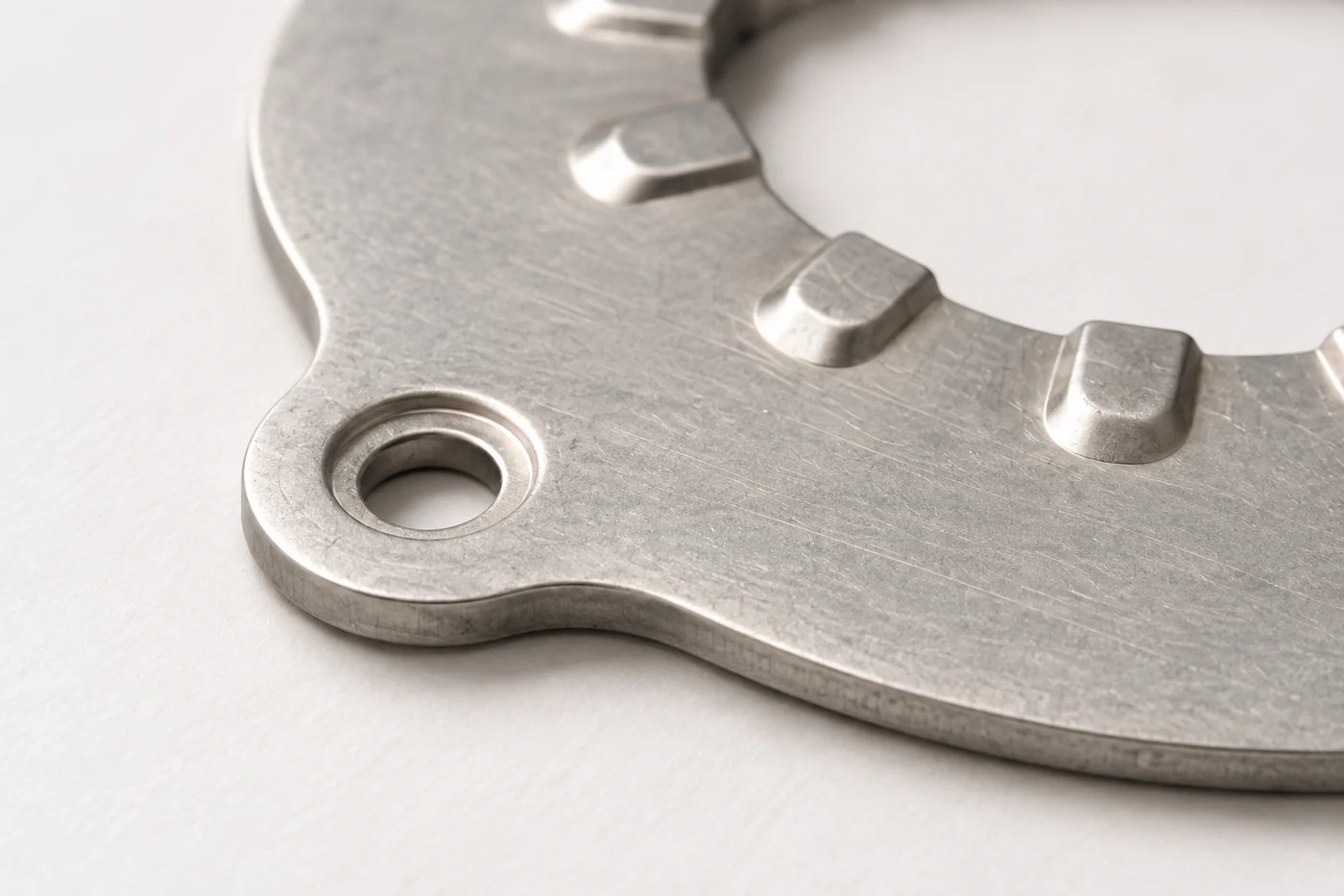
버 방향과 금형 수정 기준을 완성품 도면에 연결합니다
버 방향을 프레스의 ‘위·아래’로만 지정하면 뒤집기나 후속 공정에서 혼동할 수 있습니다. 제품 기준면을 정해 ‘B면 방향 버 허용’처럼 표시합니다. 역방향 피어싱이나 복합 공정은 절단선별 실제 방향을 확인합니다.
‘버 없을 것’만으로는 공급자와 구매자의 판정이 달라질 수 있습니다. 허용 높이, 측정 위치, 검사 수량과 기준면을 정하고 손 접촉·이물 탈락 관련 기능 요구를 별도로 적습니다. 미세 버 제거 후가공이 필요하면 모서리 형상과 중요 치수에 미칠 영향도 승인합니다.
금형 수정은 제품에서 유지해야 할 치수를 기준으로 계획합니다. 간극 변경 시 펀치와 다이 중 수정할 쪽을 명확히 해야 구멍·외곽 치수의 의도치 않은 변화를 줄일 수 있습니다. 승인값에는 목표 치수, 마모에 따른 치수 이동 방향과 재연마 후 복원 방법을 함께 포함합니다.
04정렬과 금형 수명
금형 정렬과 가압 중 간극 변화
정지 상태의 간극이 가압 중에도 그대로 유지되는 것은 아닙니다. 중심 오차, 가이드 유격, 받침·체결 상태가 국부 간극을 바꿉니다. 넓은 금형에서는 슬라이드와 볼스터의 처짐도 확인해야 합니다.
평균 간극이 같아도 양쪽 절단 조건은 달라집니다
| 원형 공구의 기하 예 | 간극 |
|---|---|
| 설계 편측 간극 | 0.08 mm |
| 중심 오차 0.03 mm가 생긴 쪽 | 0.08 − 0.03 = 0.05 mm |
| 반대쪽 | 0.08 + 0.03 = 0.11 mm |
평균은 0.08 mm여도 양쪽은 서로 다른 조건에서 잘립니다. 위 계산은 변형 없는 원형 공구의 예입니다. 실제 금형에서는 형상과 가압 변형을 추가로 확인해야 합니다.
프로그레시브 금형은 스테이션마다 작동 시점이 다릅니다. 큰 타발·성형 하중이 한쪽에 모이면 외형이 대칭이어도 하중 중심이 이동합니다. 한쪽 버는 피드 위치, 스테이션별 하중, 가압 중 정렬을 함께 확인하는 신호입니다.
스트리퍼나 홀드다운은 소재가 들리거나 휘는 정도를 제어합니다. 지지와 누름이 불충분하면 설계 간극이 적절해도 소재가 예상과 다른 자세로 절단될 수 있습니다. 반대로 누름력을 임의로 높이면 금형과 프레스에 추가 하중을 줄 수 있으므로 구조와 반력 경로를 먼저 검토합니다.
받침에서 실제 가압 조건까지 순서대로 확인합니다
- 받침·체결 상태와 이물을 확인합니다.
- 펀치·다이 장착과 가이드 상태를 확인합니다.
- 소재 이송·지지와 실제 가압 조건을 대조합니다.
간극 측정과 절삭날 검사는 장비를 정지하고 정해진 절차로 에너지를 차단한 상태에서 수행합니다. 동적 거동은 적합하게 설치된 센서와 관리된 시험 결과로 검토합니다.
날 마모·응착과 재연마 기준
절단면 악화를 모두 간극 확대로 설명할 수는 없습니다. 날 끝의 둥글어짐, 미세 치핑과 응착은 서로 다른 흔적을 남깁니다. 평균 버만 보면 한 코너에서 시작된 손상을 놓칠 수 있습니다.
| 관찰 대상 | 제품에서 확인할 흔적 | 함께 남길 기록 |
|---|---|---|
| 날 마모·둥글어짐 | 분리 전 눌림·끌림 증가, 버와 변형 | 날 사진과 위치별 버 |
| 미세 치핑 | 특정 위치에서 먼저 드러나는 날 손상 | 손상 위치와 해당 절단면 |
| 소재 응착 | 다음 제품의 긁힘, 국부 간극 감소 | 공구 부착물과 제품 긁힘 위치 |
하중·윤활·배출을 함께 대조합니다
타발력과 복귀 하중도 함께 기록합니다. 복귀 때 소재가 펀치를 강하게 붙잡으면 스트리핑에 필요한 힘이 커질 수 있고, 급격한 파단은 설비와 금형에 저장된 탄성 에너지를 풀어 충격을 만들 수 있습니다. 최대 타발력 하나만으로 마모나 응착을 진단하지 말고, 소재 두께·강도와 윤활 변화도 대조해야 합니다.
윤활 조건은 도포량뿐 아니라 공급 위치, 반복성, 소재·코팅과의 적합성으로 관리합니다. 공구강과 열처리, 표면처리는 마모·응착·파손 사이의 균형을 바꾸지만 잘못된 정렬을 해결해 주지는 않습니다. 코팅만 바꾸거나 더 단단한 재료만 선택하기 전에 손상이 마모인지, 치핑인지, 피로 파손인지 구분합니다.
슬러그가 펀치에 따라 올라오는 슬러그 풀링과 배출 정체도 별도 점검 대상입니다. 간극, 슬러그 형상, 윤활에 의한 부착, 다이 랜드와 배출 구조가 상호작용하므로 모든 문제를 같은 방법으로 해결할 수는 없습니다. 금형 제조사의 구조별 대책과 감지 기능을 검토하고, 재타발로 제품이나 날이 손상되지 않도록 관리합니다.
경보 기준과 정비 기준을 나누어 관리합니다
- 추세를 기록합니다. 중요 위치의 최대 버, 치수 이동, 날 손상과 하중 변화를 함께 봅니다. 고정 타수 하나보다 품질 한계와 추세를 연결해 재연마 시점을 정합니다.
- 수명 구간을 비교합니다. 새 날·중간 수명·정비 직전 데이터를 남겨 검사 주기와 예상 수명을 조정합니다.
- 재연마 후 승인 상태를 복원합니다. 공구 높이, 절입·스트리핑, 다이 랜드·릴리프, 보정 부품과 간섭을 확인합니다. 재조립 간극과 첫 제품의 치수·버도 다시 점검합니다.
05측정과 양산 승인
절단면 측정과 위치별 검사
같은 위치를 같은 방법으로 측정해야 변화가 보입니다. 완성품 기준면과 펀치 진입 방향을 표시하고 외곽·구멍·코너의 검사 위치를 도면에 지정합니다. 시료는 디버링 전에 보존해 원래 버와 절단 흔적을 남깁니다.
| 측정 항목 | 확인 방법 | 판단에 필요한 조건 |
|---|---|---|
| 버 높이·연속성 | 측면 광학 관찰, 적합한 형상 측정 | 원래 판 표면 기준, 위치별 최대값과 반복 측정 |
| 롤오버·전단면·파단면 | 확대 관찰과 필요한 위치의 단면 | 영역 경계, 높이·비율, 2차 전단 구분 |
| 구멍·외곽 치수 | 영상·접촉 측정, 기능 게이지 | 입구·출구·기능 높이, 버 접촉 여부 |
| 미세 균열·전단 영향부 | 단면 현미경, 필요 시 경도 분포 | 시편 준비 손상 방지, 방향·위치·측정 조건 |
| 후속 기능 | 구멍 확장·실제 성형·조립 시험 | 버 방향, 하중 경로, 균열·끼워맞춤 판정 |
기준면과 위치별 분포를 고정합니다
버 높이는 원래 판 표면을 기준으로 그 바깥까지 돌출된 높이로 정의합니다. 롤오버나 제품 휨이 있는 면을 잘못 기준으로 잡으면 값이 달라집니다. 접촉식 측정은 얇은 버를 누를 수 있고 광학 측정은 반사와 초점의 영향을 받으므로, 대상 형상에 맞는 방법을 선정하고 반복성을 확인합니다.
전단면 비율은 해당 위치의 실제 두께와 영역 높이를 함께 기록합니다. 둘레 중 가장 양호한 부분만 촬영하거나 평균값만 제시하면 국부 불량이 가려질 수 있습니다. 직선·코너·슬롯 끝처럼 변형 조건이 다른 위치를 나누고 최대값과 분포를 함께 봅니다.
시편 준비와 측정 반복성을 먼저 검증합니다
단면 시편은 절단·마운팅·연마 과정에서 버가 떨어지거나 모서리가 둥글어질 수 있습니다. 시편 준비 전 외관을 남기고, 관심 부위가 변형되지 않도록 준비 방법을 정해야 합니다. 경도 분포는 가공경화의 단서를 주지만 하중 조건과 압흔 간격에 영향을 받으므로, 경도 수치 하나를 제품 균열의 합격 기준으로 대체하지 않습니다.
계측기의 표시 분해능이 작다고 같은 수준의 측정 정확도가 확보되는 것은 아닙니다. 교정 상태와 측정자의 반복성, 고정 방법, 윤곽 인식 설정을 확인하고 요구 공차에 비해 측정 변동이 충분히 작은지 검토합니다. 검사가 경계값을 구분하지 못하면 금형 조건을 바꾸기 전에 측정 체계를 개선해야 합니다.
제품 식별값 하나로 검사 기록을 연결합니다. 소재 로트·실측 두께, 생산 시점·누적 타수, 금형·펀치 식별값, 윤활·속도를 함께 기록합니다. 같은 제품 번호에 위치별 사진과 치수·버 데이터를 연결하면 소재 변경, 마모와 정렬 문제를 구분하기 쉽습니다. 이 기록은 양산 변화의 지속적인 비교 기준이 됩니다.
간극 비교 시험과 양산 승인
합격 기준은 시험 전에 정합니다. 버 감소, 구멍 치수 유지, 후속 성형 균열 개선은 측정 우선순위가 다릅니다. 시험 후 기준을 바꾸면 보기 좋은 시편에 맞춰 조건을 선택할 수 있습니다.
후보 비교에서 수명 검증까지 네 단계로 진행합니다
- 후보 범위를 정합니다. 해당 소재·공구에 적용 가능한 제조사 자료, 공정 이력과 금형 설계를 근거로 선택합니다. 재질과 목표가 정해지지 않은 상태에서 공통 비율 세 개를 기본값으로 쓰지 않습니다.
- 조건을 고정해 비교합니다. 같은 소재 로트, 날 상태, 윤활·속도를 사용합니다. 가능하면 제품과 해당 슬러그를 짝지어 보존합니다. 버 분포·절단면·치수·타발 및 복귀 하중·후속 기능을 측정하고 합격 여부와 목표별 여유를 구분합니다. 낮은 버라도 마찰이 높거나 치수가 불안정하면 유리한 조건이 아닙니다.
- 실제 운전 범위로 넓힙니다. 후보를 좁힌 뒤 두께·강도 범위, 생산속도와 연속 운전 시간을 검증합니다. 여러 조건을 무작위로 바꾸지 않고 비교 목적에 맞게 조합합니다. 차가운 초기와 안정 운전을 구분해 시간 변동을 확인합니다.
- 마모와 로트 변화까지 확인합니다. 적절한 연속 시험이나 신뢰할 수 있는 수명 자료로 품질 변화를 확인합니다. 새 날의 통과만으로 승인하지 않습니다. 로트가 달라져도 버·치수·후속 성형이 허용 범위에 남는 운전 범위를 정합니다.
승인 기록은 변경 검증의 출발점입니다
승인서에는 공구·소재 식별, 실제 간극·두께, 속도·윤활, 검사 위치·방법, 합격 기준·정비 조건을 연결해 남깁니다. 시험 수량과 반복수는 제품 위험도, 관측 변동과 고객 요구에 맞춥니다. 몇 개의 양품만으로 공정능력을 주장하지 않으며, 통계 평가 전에는 공정 안정성과 데이터 조건을 확인합니다.
소재 공급처나 조질, 날 코팅, 펀치 형상, 프레스와 윤활을 바꾸면 기존 승인과의 차이를 검토합니다. 변경이 절단 기구와 기능에 미치는 영향에 따라 필요한 검증 범위를 정합니다. 사소해 보이는 변경을 기록하지 않으면 다음 불량에서 원인과 시점을 연결하기 어려워집니다.
06공정 선택과 발주 사양
셰이빙·파인블랭킹과 공정 선택
필요한 기능면부터 정한 뒤 공정을 선택합니다. 넓은 접촉면, 엄격한 직각도나 제한된 파단면은 일반 타발의 간극 조정만으로 확보하기 어려울 수 있습니다. 간극을 계속 줄이면 마찰·하중·공구 손상이 커질 수 있습니다.
| 공정·조건 | 품질을 만드는 방식 | 검토할 전제 |
|---|---|---|
| 셰이빙 | 먼저 타발한 면의 얇은 여유를 추가 절삭해 면과 치수 개선 | 첫 공정의 치수·위치, 여유량과 균일성, 지지 조건. 작은 여유나 초기 면 변형은 마무리를 불안정하게 만들 수 있습니다. |
| 파인블랭킹 | 소재 구속, 카운터펀치·대향력, 날 형상으로 절단 영역 응력 제어 | 매우 작은 간극만으로 구현되지 않습니다. 일반 다이를 좁히는 것만으로 같은 품질과 수명을 기대할 수 없습니다. |
| 음의 클리어런스 | 펀치가 다이 개구보다 큰 특수 조건에서 소재 흐름·압축 상태 활용 | 분리 과정과 공구 간섭을 고려한 구조가 필요합니다. 기존 일반 금형의 간극을 단순히 0 아래로 줄이는 설정이 아닙니다. |
연구 조건과 양산 실증을 구분해 읽습니다
2009년 실험은 3.0 mm A1050-O·A5052-H34 판재, 1 mm/s의 지정 조건을 비교했습니다. 음의 간극 시험은 충돌을 피하려고 두께의 90% 침입에서 제한한 반블랭킹 상태를 포함합니다. 큰 음의 간극에서 파단면 억제와 후반 하중 증가가 관찰되었습니다.
이 결과는 압축 응력과 파단의 관계를 설명합니다. 완전히 분리된 무버 제품의 양산 실증이나 다른 강종의 권장 간극표로 해석해서는 안 됩니다.
정밀도가 필요한 범위와 총 공정비를 비교합니다
선택은 필요한 면의 기능 범위와 총 공정비를 함께 비교합니다. 모든 외곽이 아니라 특정 구멍만 정밀하다면 리밍 등 해당 부위의 후가공이 적합할 수 있고, 전단면 전체와 대량 생산성이 중요하면 전용 정밀 타발 공정이 검토 대상이 됩니다. 디버링, 셰이빙과 파인블랭킹은 서로 다른 문제를 해결하므로 같은 대안으로 묶어 비교하지 않습니다.
공정 변경에는 추가 설비·금형 비용뿐 아니라 이송, 세척과 칩·스크랩 관리, 치수 재검사도 포함합니다. 최종 단가를 비교할 때는 후공정을 추가해 얻는 품질 여유와 일반 타발에서 반복되는 정비·선별 비용을 같은 생산량과 검사 기준으로 평가해야 합니다.
발주 사양과 양산 관리 기준
구매자는 기능과 판정 기준을, 제작자는 공정과 검증 방법을 명확히 합니다. 근거 없는 간극 비율을 도면에 고정하면 소재·날 상태가 변할 때 품질을 유지할 조정 여지가 줄어듭니다.
| 발주·승인 항목 | 준비할 정보 | 연결할 판단 |
|---|---|---|
| 소재와 생산 조건 | 규격·조질, 두께·강도 범위, 표면 상태, 생산량 | 후보 간극과 공구·윤활, 검증 로트 |
| 제품 기능 | 조립면, 접촉 길이, 후속 성형, 버 허용 방향 | 관리할 절단면과 치수 우선순위 |
| 도면 판정 | 치수 기준면, 버 높이·위치, 모서리 요구 | 측정 방법·검사 위치·합격 기준 |
| 금형과 설비 | 공구 식별·재연마, 정렬·지지, 이송·배출 | 실제 간극과 하중, 유지보수 조건 |
| 양산 이관 | 승인 범위, 검사 주기, 경보·정비 기준, 변경 절차 | 마모·소재 변동에도 기능을 유지하는 관리 |
견적은 유지보수와 후공정까지 같은 범위로 비교합니다
견적 비교에는 금형비와 1회 타발 비용 외에 재연마, 공구 교체, 정지 시간과 검사·선별, 디버링 및 불량 손실을 포함합니다. 초기 버가 조금 낮은 조건이 공구 수명을 짧게 만들면 전체 비용이 늘 수 있습니다. 반대로 후공정을 줄일 수 있을 만큼 기능면이 안정된다면 초기 금형 투자가 더 합리적일 수 있습니다.
양산 이관 시 관리점을 세 가지로 정리합니다
- 중요 위치를 지정합니다. 평균과 최악 위치를 나누어 관리합니다. 평균 버가 양호해도 체결 구멍 한쪽 버가 조립을 막으면 기능 불합격입니다. 도면 중요 부위와 시험에서 먼저 악화된 위치를 우선 관리합니다.
- 이상 발생 조건을 남깁니다. 소재·윤활·이송과 중요 위치의 품질 추세를 확인합니다. 이상 위치·시간·조건을 기록한 뒤 원인을 분리합니다.
- 정비 후 승인 상태를 확인합니다. 재연마·공구 교체 후 치수와 절단면이 승인 상태로 돌아왔는지 확인해 초기 승인, 반복 생산과 유지보수에 같은 기준을 적용합니다.
English Technical Overview
Press die clearance is the gap between the cutting edges of the punch and die. It changes how sheet material deforms and separates. This affects cut edges, burrs, dimensions, tooling loads and cracking in later forming.
A suitable clearance is an operating range that supports both part function and repeatable production. The same material and thickness can behave differently as geometry, edge condition or alignment changes. Before reducing clearance or increasing press tonnage to address a high burr, establish what changed and where.
Align the definitions
Distinguish single-side from total clearance. Record the physical gap together with actual sheet thickness.
Judge the function
Burnished-zone length alone is insufficient. Compare burrs, dimensions, loads and downstream results together.
Approve the life range
Review parts from fresh tooling through to resharpening. Connect drawing dimensions, burr direction, downstream deformation and wear.
01Clearance and cut-edge fundamentals
Single-side and total clearance
In circular piercing, total clearance is the die diameter minus the punch diameter. Half this value is the radial gap on one side, or single-side clearance.
Match clearance conventions before comparing percentages
“10% clearance” means a gap of 10% of sheet thickness on each side if the convention is single-side. If it means the total, each side is 5%. The physical gap differs by a factor of two, so check the convention before comparing a manufacturer’s table with a tooling drawing.
For a non-circular profile, measure the local gap between corresponding cutting edges normal to the profile. The difference between circumscribed diameters is not a substitute.
| Item | Calculation basis | Example |
|---|---|---|
| Sheet thickness | Reference for the clearance ratio | 1.00 mm |
| Punch and die diameters | Circular piercing edge dimensions | Punch 10.00 mm · die 10.16 mm |
| Total clearance | Die diameter − punch diameter | 0.16 mm · 16% of thickness |
| Single-side clearance | Diametral difference ÷ 2 | 0.08 mm = 80 μm · 8% of thickness |
Record actual thickness and assembled condition
The table illustrates conventions and units; it does not recommend a gap for a particular material. With the same tooling, 0.95 mm and 1.05 mm sheets still have a 0.08 mm gap per side. Their clearance ratios are approximately 8.42% and 7.62%. Nominal thickness alone can conceal this difference.
Design clearance also differs from the effective gap during operation. Manufacturing tolerances, wear, material pickup, assembly alignment and deflection under load change the local gap. Individually compliant punch and die dimensions do not guarantee uniform clearance around the assembled profile.
Record both dimension and ratio: “0.08 mm per side, 1.00 mm reference thickness, 8%.” Include punch and die measurement locations, the date and resharpening condition to compare tooling changes consistently.
Four cut-edge zones and crack paths
In conventional blanking, punch contact first causes elastic deformation, followed by plastic deformation near the cutting edges as load rises. Cracks then grow from the punch and die sides and join, separating the part from the scrap.
Identify the component and punch direction first
- Rollover: the rounded entry edge of a pierced hole in the retained sheet.
- Burnished or shear zone: the relatively smooth band below it.
- Fracture zone: the region formed by crack propagation.
- Burr: the projection beyond the sheet surface at the punch exit.
This sequence runs from the punch entry face of the retained sheet after piercing. It is reversed on the outside edge of the separated slug or blanked product. Mark the component and punch direction to avoid reading the same photograph backwards.
Rollover reflects material flow as the edge is pressed down. Fracture-zone inclination reflects deformation and crack paths from the two cutting edges. Entry and exit diameters can therefore differ, and an outside profile can slope through its thickness. Function depends on which section engages the mating part.
Look beyond burnish length and brightness
A long burnished band does not establish overall cutting quality. If cracks fail to join appropriately, secondary shearing can create a second smooth band. Treating it as an improvement can overlook extra loading and local deformation.
Check burr height above the original sheet surface, root shape and continuity. Long thin burrs and short stiff burrs can differ in damage or detachment risk and removal method. Supplement face-on photographs with side views and sections at relevant locations.
Lighting and reflection angle also change photographic brightness. Confirm burnish and fracture boundaries microscopically, then compare them with surface profiles or sections. Linking these observations to production history makes the edge a useful record of tooling condition.
02Quality diagnosis and selection
Diagnosing small and large clearance
A high burr alone does not establish whether clearance is too large or too small. Edge shape, loads and burr location must be assessed together to narrow down the cause.
Distinguish the effects of small and large clearance
Small clearance changes material constraint and crack connection between the cutting edges. Secondary shearing and strong friction can increase cutting or stripping loads. Check a long burnished band alongside rubbing marks and local punch wear.
Large clearance permits more bending and rotation. Rollover, fracture inclination and entry-to-exit dimensional differences may increase. Excessive clearance can produce large burrs and an unstable edge. However, burr height does not increase continuously with clearance for every material.
Dayton’s high-speed piercing guidance describes a particular engineered-clearance region where a wider gap can reduce burrs and withdrawal-related wear. Using that benefit requires control of hole dimensions, rollover, fracture inclination and slug pulling. It is not an unconditional recommendation for large clearance.
Use defect location and edge condition to verify the cause
| Observation | Possible causes | Next check |
|---|---|---|
| Second burnished band · high withdrawal load | Small gap · friction · material pickup | Secondary shearing in sections · punch sidewall · actual gap |
| Large rollover · inclined fracture face | Large gap · insufficient support · deformation | Entry and exit dimensions around the profile · hold-down condition |
| Burr concentrated on one side | Eccentricity · alignment or guiding problems · local edge damage | Circumferential burr map · assembled and loaded alignment |
| Burrs and scratches increase during production | Wear · chipping · adhesion · lubrication changes | Edge condition · stroke count · material lot · lubrication history |
| Acceptable appearance but forming cracks | Work hardening or microdamage in the shear-affected zone | Forming with actual burr orientation · cross-sections |
Match cutting-edge condition and lubrication in comparison trials. Measure the same locations with the same method. Mixing sharp and worn tooling can obscure clearance effects because edge rounding and microchipping also change deformation and burr formation.
For a one-sided burr, examine its distribution before changing average clearance. If one side is narrow and the other wide, enlarging the whole die affects them differently. Compare several directions around a circular hole, or both sides and both ends of a slot.
Link each correction to a verified causal hypothesis. If recurring high burrs coincide with tool-edge chipping, investigate the damage and restore the edge first. After correction, compare dimensions, loads and downstream results as well as burrs.
Material, thickness and geometry effects
A material designation alone cannot determine the final clearance. Review supply condition, actual thickness, part profile, tooling structure and downstream function together.
Read manufacturer values with their stated conditions
Heat treatment, temper and cold work change strength and ductility within the same alloy. Link the certified strength range, hardness or supply condition to measured incoming thickness. This record helps explain results after a material change.
Ductile sheet deforms further before separation, changing rollover and burnish. High-strength sheet can impose greater stress and shock on the edges. Microstructure and local ductility affect later edge cracking. Pickup on aluminium or some stainless steels changes effective edge geometry and friction, so review material-specific lubrication and tooling measures.
For straight or gently curved edges in SPC mild steel, MISUMI describes a life-oriented single-side clearance of about 6–8% and a burnished length of about 30%. These are not universal acceptance limits. Its guidance also notes that corner flow changes burnish and wear. Check material, thickness, tooling family and quality objective before using a manufacturer’s table as a trial starting point.
Review small holes and corners separately
- Small holes: check the hole-diameter-to-thickness ratio. Even at the same clearance per side, slender punches have smaller sections and less lateral support. Review buckling, breakage and withdrawal resistance closely. Do not automatically reuse the outside-profile setting.
- Slot ends, internal corners and narrow connecting features: check concentrated deformation and local edge stiffness. A straight-edge setting may not suit these regions. Consider edge radius, corner geometry, surrounding scrap width and material restraint area.
Record rolling direction relative to the cut. Pooling differently oriented samples can hide variation when anisotropy is strong or the next operation stretches the edge. Sampling positions across and along the coil also clarify comparisons between lots.
Major holes, outside profiles and small corners can have different requirements within one part. Their functions may justify separate operations or dedicated finishing.
03Part function and drawing requirements
Cut-edge function and downstream formability
Start edge evaluation with the function the edge performs. A simple outside edge, a locating hole, an edge near a seal and a flange edge to be stretched have different requirements.
Forming damage can remain after deburring
Function sets the priority among burnish proportion, burr height and entry diameter. A locating hole may depend more on engagement length, roundness and its through-thickness profile than on expansion capacity. A heavily stretched edge may perform better with less damage, even if its smooth band is shorter.
Downstream forming requires checks of work hardening and microdamage as well as visible burrs. The shear-affected zone has already undergone substantial plastic strain and can initiate cracks when stretched again. Deburring may leave internal damage, so it cannot be assumed to restore forming capacity.
Reviewing drawing defects and forming conditions alongside edge preparation helps distinguish material-flow problems from cut-edge problems.
Interpret hole expansion with its test conditions
A hole expansion test compares edge stretchability for a specific material and cutting condition. If a 10 mm hole reaches 15 mm at the specified crack criterion, the diameter increase is (15 − 10) ÷ 10 × 100 = 50%. This example does not directly specify allowable flange height or stretching in a production part.
Results depend on hole preparation, initial diameter, punch geometry, burr orientation and crack detection. Values from different conditions are not an intrinsic material constant. Distinguish standardized comparisons from trials reproducing production. Record the standard edition and specimen preparation in the report.
With a conical punch, results can differ when the burr faces the punch or the freely expanding outer side. This does not establish one burr-direction rule for all bending and flanging. Check the actual contact face and tensile side.
Approval should record where and when cracks start in the next operation. Looking only for large cracks after forming can miss early microcracks. Specify functional areas needing magnified or sectional inspection, then connect them to a practical production acceptance method.
Drawing dimensions and burr direction
In piercing, the sheet with the hole is the product and the removed slug is scrap. In blanking, the separated outline is the product and the surrounding strip is scrap.
Define the reference cutting edge and measurement height
| Item | General reference | Additional drawing or inspection details |
|---|---|---|
| Pierced hole | Punch dimensions | Entry, exit or functional-height dimension · position · roundness |
| Blanked outline | Die dimensions | Measurement face · profile tolerance · through-thickness slope |
| Burr on a pierced product | Usually the punch exit side | Finished faces A and B · permitted direction |
| Burr on a blanked product | Usually the punch contact side | Final assembly direction after removal or turnover |
| Edge finishing | Distinguish deburring, chamfering and rounding | Permitted material removal · protected functional surfaces |
The table describes conventional positive-clearance operations. Finished dimensions need not exactly match punch or die dimensions. Elastic recovery, edge wear and the through-thickness cut profile affect the result.
Specify measurement height. Check whether a contact probe touches rollover or burrs, and which contour an optical system detects. For mating features, assign appropriate roles to pass-through gauges and actual dimensional measurements over the engagement length.
Link burr direction and tooling changes to the finished drawing
Press “top” and “bottom” can become ambiguous after turnover or later operations. Use part datums, such as “burr permitted toward face B.” Verify each cut’s actual direction for reverse piercing or combined operations.
“No burrs” alone can produce different supplier and buyer decisions. Define allowable height, measurement locations, sample quantity and the reference surface. Add requirements for handling or particle detachment where relevant. If small burrs require finishing, approve its effects on edge shape and critical dimensions.
Plan tooling changes around the product dimension to be maintained. State whether the punch or die will change when adjusting clearance. This reduces unintended changes to holes or outside profiles. Approval should include the target dimension, its drift direction with wear and restoration after resharpening.
04Alignment and tool life
Alignment and clearance under load
The stationary gap does not necessarily remain unchanged under load. Centre offset, guide play, die support and clamping alter local clearance. Wide dies also require attention to slide and bolster deflection.
The same average can conceal unequal cutting conditions
| Circular-tool geometry example | Clearance |
|---|---|
| Designed single-side clearance | 0.08 mm |
| Side narrowed by a 0.03 mm centre offset | 0.08 − 0.03 = 0.05 mm |
| Opposite side | 0.08 + 0.03 = 0.11 mm |
The average remains 0.08 mm, but the two sides cut under different conditions. This example assumes rigid circular tooling. Actual dies require further assessment of geometry and deformation under load.
Progressive-die stations engage at different points in the stroke. Concentrated cutting or forming loads can move the load centre even in a symmetrical die. A one-sided burr calls for checks of feed position, station loads and alignment under load.
Strippers and hold-downs control sheet lifting and bending. Inadequate support or restraint can change the sheet’s cutting position despite an appropriate design gap. Arbitrarily increasing hold-down force can add load to the die and press, so check the structure and reaction path first.
Inspect from die support through to operating loads
- Check die support, clamping and debris.
- Inspect punch and die mounting, then guide condition.
- Compare feeding, material support and actual loading conditions.
Measure clearance and inspect cutting edges with the machine stopped and energy isolated under the applicable procedure. Assess dynamic behaviour using suitably installed sensors and controlled trial results.
The rated tonnage point, energy and eccentric loading discussed in press tonnage selection are directly relevant. Nominal force reserve does not guarantee alignment under load, and suitability of the available equipment must be checked against die size, load distribution and operating conditions. Separating structural causes before changing clearance reduces unnecessary tooling modifications.
Wear, adhesion and resharpening criteria
Increasing clearance does not explain every decline in edge quality. Edge rounding, microchipping and adhesion leave different evidence. Average burr height can conceal damage that begins at one corner.
| Observation | Evidence on the part | Records to connect |
|---|---|---|
| Wear or edge rounding | More compression or dragging before separation; burrs and deformation | Edge photographs and burrs by location |
| Microchipping | Local cutting-edge damage | Damaged location and its corresponding cut edge |
| Material adhesion | Scratches on subsequent parts; locally reduced gap | Tool deposits and scratch locations |
Compare loads, lubrication and discharge
Record cutting and withdrawal loads together. Strong sheet grip on the returning punch can increase stripping force, while abrupt fracture can release stored elastic energy from the die and machine as shock. Peak cutting force alone cannot diagnose wear or adhesion; compare incoming thickness, strength and lubrication changes as well.
Control lubrication by application location, repeatability and compatibility with the material and coating, not only quantity. Tool steel, heat treatment and surface treatment change the balance among wear, adhesion and fracture, but do not correct misalignment. Before changing a coating or selecting a harder material, distinguish abrasive wear, chipping and fatigue failure.
Slug pulling, in which scrap rises with the punch, and obstructed discharge require separate checks. Clearance, slug geometry, lubricant-related adhesion, die land and discharge design interact, so a single remedy does not suit every problem. Review design-specific measures and detection with the tooling supplier to prevent recutting from damaging parts or cutting edges.
Separate warning levels from maintenance limits
- Record trends. Review maximum burrs at critical locations, dimensional drift, edge damage and load changes together. Link resharpening to quality limits and trends rather than one fixed stroke count.
- Compare life stages. Keep fresh-tool, mid-life and pre-maintenance records to adjust inspection intervals and expected life.
- Restore the approved condition after sharpening. Check tool height, penetration, stripping, die land and relief, adjustment components and interference. Recheck assembled clearance and first-part dimensions and burrs.
05Measurement and production approval
Cut-edge measurement and location-based inspection
Changes become visible when the same locations are measured by the same method. Mark the finished-part reference face and punch entry direction. Identify profile, hole and corner inspection positions on the drawing, and preserve specimens before deburring to retain the original cutting evidence.
| Characteristic | Method | Conditions needed for interpretation |
|---|---|---|
| Burr height and continuity | Side-view optical inspection; suitable profile measurement | Original sheet-surface reference; local maxima and repeat measurements |
| Rollover, burnish and fracture zones | Magnified inspection and selected cross-sections | Zone boundaries, heights and proportions; secondary shear identified separately |
| Hole and outside dimensions | Optical or contact measurement; functional gauges | Entry, exit or functional height; contact with burrs |
| Microcracks and shear-affected zone | Section microscopy and hardness profiles where needed | Avoided preparation damage; orientation, location and test conditions |
| Downstream function | Hole expansion, actual forming or assembly trials | Burr direction, loading path and crack or fit criteria |
Fix the reference and track the distribution by location
Define burr height as the projection beyond the original sheet surface. Using a rolled-over or distorted surface as the wrong reference changes the result. Contact measurement can compress a thin burr, while optical methods are affected by reflection and focus. Select a method appropriate to the geometry and verify repeatability.
Record actual local thickness along with burnished-zone height when reporting its proportion. Photographing only the best circumferential location or reporting only averages can conceal local defects. Separate straight edges, corners and slot ends, and review maxima together with the distribution.
Verify specimen preparation and measurement repeatability
Section cutting, mounting and polishing can detach burrs or round the edge. Record the appearance before preparation and select a method that preserves the region of interest. Hardness profiles provide evidence of work hardening but depend on test load and indentation spacing; one hardness value cannot replace a product crack-acceptance criterion.
A fine display resolution does not establish equivalent measurement accuracy. Check calibration, operator repeatability, fixturing and optical contour settings, and establish whether measurement variation is sufficiently small relative to the required tolerance. If inspection cannot distinguish borderline results, improve the measurement system before changing the die condition.
Connect inspection records through one part identifier. Record material lot and actual thickness, production time and accumulated strokes, die and punch identities, lubrication and speed. Linking local photographs and dimensional and burr data helps distinguish material changes, wear and alignment problems. The records provide an ongoing reference for production changes.
Clearance trials and production approval
Define acceptance criteria before testing. Burr reduction, hole-size stability and resistance to downstream cracking require different measurement priorities. Changing criteria afterwards risks selecting a condition merely because one specimen looks attractive.
Move from candidate comparison to life validation in four stages
- Select a candidate range. Use manufacturer guidance applicable to the material and tooling, process history and die design. Do not adopt three universal percentages before the material and quality objectives are known.
- Compare under fixed conditions. Use the same material lot, edge condition, lubrication and speed. Retain each part with its slug where practical. Measure burr distribution, edge profile, dimensions, cutting and withdrawal loads, and downstream function. Record compliance separately from margin to each objective. A low burr is not an advantage if friction is high or dimensions are unstable.
- Extend to the operating range. After narrowing candidates, validate the thickness and strength range, production speed and continuous running duration. Plan combinations for the comparison rather than changing factors arbitrarily. Separate cold startup from stable operation to identify variation over time.
- Verify wear and material-lot changes. Use an appropriate continuous trial or reliable life data to assess quality change. Fresh-tool acceptance alone is insufficient. Establish a range in which burrs, dimensions and downstream forming remain acceptable across lots.
Use the approval record as the basis for change validation
The approval record should connect tool and material identity, actual clearance and thickness, speed and lubrication, inspection locations and methods, acceptance criteria and maintenance conditions. Set quantities and repetitions from product risk, observed variation and customer requirements. A few acceptable parts do not establish process capability. Check stability and data conditions before statistical assessment.
Review the existing approval whenever the material supplier or temper, tool coating, punch geometry, press or lubricant changes. Set the revalidation scope according to the change’s effect on cutting mechanisms and function. Unrecorded changes that appear minor make subsequent defects harder to connect to a cause and time.
06Process selection and purchasing
Shaving, fineblanking and process selection
Define the required functional surface before choosing a process. A large bearing surface, tight squareness or a restricted fracture zone can exceed what clearance adjustment in conventional blanking can achieve. Continually reducing the gap can increase friction, loads and tool damage.
| Process or condition | How quality is achieved | Conditions to examine |
|---|---|---|
| Shaving | Removes a thin allowance from a previously blanked edge to improve profile and dimensions | First-operation dimensions and position, allowance size and uniformity, and support. Too little allowance or initial distortion can prevent consistent finishing. |
| Fineblanking | Controls cutting-zone stress through restraint, counterpunch or opposing force, and edge geometry | An extremely small gap alone is insufficient. Narrowing a conventional die does not establish equivalent quality or tool life. |
| Negative clearance | Uses a punch larger than the die opening in a special arrangement that controls flow and compression | The design must account for separation and tool interference. It is not simply a below-zero setting in an existing conventional die. |
Distinguish experimental conditions from production evidence
A 2009 experiment compared 3.0 mm A1050-O and A5052-H34 sheet at 1 mm/s in specified tooling. Negative-clearance tests included a half-blanked condition limited to 90% thickness penetration to prevent collision. Large negative clearance suppressed the fracture zone and increased late-stage load.
The result helps explain the relationship between compression and fracture. It does not demonstrate production of fully separated, burr-free parts or provide recommended clearances for other grades.
Compare the extent of precision with total process cost
Compare the functional extent of the required surface with total process cost. If only selected holes require precision, a local finishing operation such as reaming may be appropriate; if the complete cut surface and high-volume output matter, a dedicated precision blanking process merits review. Deburring, shaving and fineblanking address different problems and should not be treated as interchangeable alternatives.
A process change includes feeding, cleaning, chip or scrap management and dimensional reinspection as well as added equipment and tooling cost. Compare the quality margin gained by finishing with recurring maintenance and sorting costs in conventional blanking, using the same production volume and inspection criteria.
Purchasing specifications and production control
The buyer defines function and acceptance; the toolmaker defines the process and validation method. Fixing an unsupported clearance percentage on the drawing can restrict adjustments needed when material or edge condition changes.
| Purchasing and approval item | Information to prepare | Decision supported |
|---|---|---|
| Material and production | Specification and temper, thickness and strength ranges, surface condition, volume | Candidate clearance, tooling and lubrication, validation lots |
| Part function | Mating surfaces, engagement length, downstream forming, permitted burr direction | Priority edges and dimensions |
| Drawing acceptance | Dimensional reference face, burr height and locations, edge requirements | Measurement method, locations and acceptance limits |
| Tooling and equipment | Tool identity and resharpening, alignment and support, feeding and discharge | Effective clearance, loading and maintenance conditions |
| Production release | Approved range, inspection intervals, warning and maintenance criteria, change procedure | Maintaining function through wear and material variation |
Compare quotations on the same maintenance and finishing basis
Cost comparisons should include resharpening, tool replacement, downtime, inspection and sorting, deburring and scrap losses as well as die cost and cost per stroke. A condition producing slightly lower initial burrs can raise total cost if it shortens tool life. Conversely, an initial tooling investment can be justified if a stable functional surface eliminates a finishing operation.
Define three control points for production handover
- Identify critical locations. Control average behaviour separately from the worst relevant location. A good average burr does not establish function if a burr on one side of a fastening hole prevents assembly. Prioritise critical drawing features and the locations that deteriorated first in trials.
- Record abnormal conditions. Track material, lubrication, feeding and quality trends at critical locations. Record the abnormality’s position, time and conditions before separating causes.
- Verify the approved state after maintenance. Confirm that dimensions and edge quality return to the approved condition after resharpening or replacement. Apply consistent criteria to initial approval, repeated production and maintenance.
For an ID METAL press processing review, prepare the finished drawing, material supply condition, actual thickness range, burr direction and downstream-operation details. Sharing them in a manufacturing inquiry allows dimensions, edge quality and process cost to be assessed on a common basis. Approve the final condition from defined product function and results verified with the actual tooling and material.
추가 정보
주제 요약
프레스 금형 클리어런스는 펀치와 다이 절삭날 사이의 간극입니다. 편측·양측 표기와 실제 판 두께를 먼저 맞춘 뒤 절단면·버·치수·하중·후속 성형을 함께 비교해야 합니다. 새 날의 외관만으로 결정하지 말고 정렬, 소재 변동과 마모를 포함한 운전 범위를 승인하는 것이 핵심입니다.
핵심 포인트
- 간극은 편측·양측 기준을 명시하고 길이와 두께 대비 비율을 함께 기록합니다.
- 전단면이 길수록 좋은 조건이라는 판단과 버가 간극에 비례한다는 판단은 모두 피합니다.
- 피어싱 구멍과 블랭킹 외곽은 치수 기준 공구와 제품 버 방향을 구분합니다.
- 한쪽 버는 평균 간극보다 정렬·국부 마모·가압 변형을 먼저 확인해야 할 신호일 수 있습니다.
- 절단 가장자리를 다시 늘리는 제품은 버 외에 전단 영향부의 손상과 실제 성형성을 확인합니다.
- 최종 승인에는 새 날부터 정비 전까지의 품질 추세와 소재·공구 변경 절차를 포함합니다.
FAQ
클리어런스 10%는 편측 기준입니까?
자료마다 다를 수 있습니다. 편측 10%와 양측 합계 10%는 실제 간극이 두 배 차이 납니다. 원형 금형은 다이 지름과 펀치 지름의 차이가 양측 간극이며, 그 절반이 편측 간극입니다.
버가 높으면 간극을 바로 줄여야 합니까?
먼저 위치별 버와 날 상태, 정렬을 확인해야 합니다. 큰 간극뿐 아니라 마모·치핑·응착과 편심도 버에 영향을 줍니다. 원인을 분리한 뒤 간극을 수정하고 치수와 하중까지 다시 확인합니다.
전단면이 길면 더 좋은 절단면입니까?
항상 그렇지는 않습니다. 2차 전단이나 높은 마찰 때문에 매끈한 띠가 길어질 수 있으며, 후속 성형에서는 가공경화와 미세 손상이 더 중요할 수 있습니다. 기능면의 접촉 길이·치수·균열 기준으로 판단합니다.
피어싱과 블랭킹은 버 방향이 같습니까?
일반적인 양의 간극 공정에서는 다릅니다. 피어싱 제품은 보통 펀치 출구 쪽, 블랭킹으로 떼어낸 제품은 펀치 접촉 쪽에 버가 생깁니다. 완성품의 기준면으로 방향을 지정하고 역방향·복합 공정은 따로 확인합니다.
디버링을 하면 후속 성형 균열도 해결됩니까?
버를 없애도 전단 영향부의 가공경화와 내부 손상이 남을 수 있습니다. 실제 버 방향과 성형 조건으로 기능을 확인하고, 필요하면 절단 조건이나 가장자리 마무리 방법을 함께 검토해야 합니다.
간극 검토를 의뢰할 때 어떤 자료가 필요합니까?
완성품 도면, 소재 규격·조질과 두께 범위, 중요 치수, 버 높이·방향, 후속 성형·조립 조건을 준비합니다. 기존 금형이면 펀치·다이 치수, 날 상태와 생산 이력, 위치별 불량 사진을 함께 전달하면 진단에 도움이 됩니다.
관련 주제
버 높이와 측정 기준면
버 높이는 원래 판 표면 바깥으로 돌출된 높이로 정의해야 합니다. 측정 위치와 최대값, 접촉·광학 방식의 반복성을 함께 지정하면 공급자와 구매자가 같은 기준으로 판정할 수 있습니다.
후속 성형과 구멍 확장 시험
확장률은 소재뿐 아니라 절단 조건, 구멍 크기, 펀치 형상과 버 방향에 영향을 받습니다. 서로 다른 시험 결과를 직접 비교하지 말고, 표준 비교 시험과 실제 제품 검증의 역할을 나누어 사용합니다.
재연마와 변경 관리
날 마모와 치핑·응착을 구분하고 중요 위치의 버·치수·하중을 함께 추적합니다. 재연마 뒤에는 공구 높이·절입·스트리핑과 조립 간극을 확인하며, 소재·코팅·윤활 변경은 승인 조건과 대조합니다.
내부 링크
절단 조건과 장비 하중을 함께 검토할 때는 프레스 톤수 선정을, 타발 뒤 성형에서 균열이 발생할 때는 딥드로잉 균열과 주름을 참고하실 수 있습니다. 소재 조질과 스프링 특성을 함께 검토하는 동합금 부품은 인청동·베릴륨동·황동 비교와 연결해 살펴볼 수 있습니다.
실제 가공 검토는 정밀 프레스 부품과 설비 라인업을 바탕으로 제품 도면, 소재 상태, 버 허용면과 후공정 요구를 함께 확인하는 순서로 진행합니다. 관련 도면과 검사 조건은 개발의뢰를 통해 전달하실 수 있습니다.