
딥드로잉 균열과 주름: 프레스 성형 불량의 원인과 대책
딥드로잉 공정에서 주름을 누르려고 블랭크 홀더 하중을 높이면 벽이 갈라지고, 균열을 줄이려고 하중을 낮추면 플랜지에 주름이 생길 수 있습니다. 판재를 다이 안으로 끌어들이는 힘과 소재 유입을 제어하는 저항이 균형을 이루지 못하면 두 불량이 번갈아 나타납니다. 해법은 결함이 시작된 위치와 시점을 찾고, 소재가 실제로 얼마나 들어왔으며 어느 부분이 얇아졌는지 확인하는 데서 출발합니다.
안정적인 프레스 성형 조건은 한 번 완성품을 얻은 설정값보다 넓어야 합니다. 판 두께와 재료 특성, 윤활 상태, 금형 온도가 정상적인 생산 범위에서 달라져도 균열·주름·치수 불량이 발생하지 않는 여유가 필요합니다. 블랭크, 금형, 재료와 검사 기준을 함께 검토해야 이 여유를 설계하고 유지할 수 있습니다.
소재 유입과 변형 영역
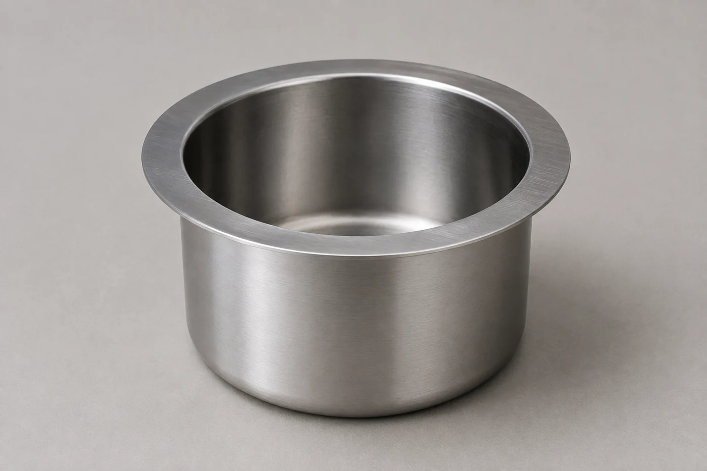
딥드로잉은 평평한 판재인 블랭크를 펀치와 다이로 컵이나 상자 형태로 만드는 성형 방식입니다. 펀치가 내려가면 바깥쪽 플랜지의 소재가 다이 입구를 지나 벽으로 들어옵니다. 바닥을 계속 늘려 깊이를 확보하는 성형과 달리, 필요한 벽 면적을 외곽에서 공급하는 흐름이 핵심입니다.
플랜지는 반경 방향으로 당겨지는 동시에 원주 방향으로 압축됩니다. 큰 원 둘레에 있던 소재가 더 작은 둘레로 이동하기 때문에 둘레 길이가 줄어야 하기 때문입니다. 이 압축을 판재가 평평한 상태에서 받아들이지 못하면 두께 방향으로 솟아오르며 좌굴하고, 그 결과 플랜지 주름이 형성됩니다.
벽은 펀치가 가하는 힘을 플랜지에 전달하는 통로입니다. 소재를 끌어오는 데 필요한 힘이 커지면 벽과 바닥의 연결부에 인장 부담이 집중될 수 있습니다. 여기에서 국부적으로 얇아지는 네킹이 발생하면 하중을 견디는 단면이 더 작아져 변형이 집중되고, 결국 찢어짐으로 이어질 수 있습니다.
다이 어깨에서는 판재가 평면에서 곡면으로 굽혀진 뒤 다시 벽 방향으로 펴집니다. 따라서 이 부위의 저항에는 마찰뿐 아니라 굽힘과 펴짐에 필요한 힘도 포함됩니다. 평평한 펀치 바닥 위에서는 상대적으로 변형이 작을 수 있지만, 돔형 바닥이나 돌출 형상이 있으면 그 영역의 늘어나는 변형까지 함께 검토해야 합니다.
사각 제품에서는 코너와 직선 벽의 흐름이 다릅니다. 코너의 플랜지는 원통 컵과 비슷하게 둘레가 줄어드는 변형을 겪는 반면, 직선 구간에서는 다이 어깨를 넘어 굽혀지고 펴지는 흐름이 큰 비중을 차지합니다. 전체 둘레에 같은 구속을 주어도 코너에서 소재가 남거나 특정 벽에서 공급이 부족해질 수 있습니다.
공정 검토는 블랭크 안착, 홀더 접촉, 초기 굽힘, 본격적인 유입, 하사점 부근의 형상 완성, 이형과 트리밍 순서로 나누면 명확해집니다. 각 단계에서 새로 생기는 접촉과 변형을 구분하면 최초 원인을 찾기 쉽습니다. 완성품의 가장 큰 주름이나 가장 긴 균열이 반드시 처음 불량이 발생한 위치를 뜻하지는 않습니다.
균열·주름·이어링의 구별
결함 이름을 정확히 나누어야 대책도 맞출 수 있습니다. 벽이 얇아진 뒤 찢어진 균열과 절단면에서 바로 시작된 균열은 같은 인장 불량으로 묶기 어렵습니다. 플랜지의 좌굴 주름과 컵 가장자리 높이가 방향에 따라 달라지는 이어링도 서로 다른 현상입니다.
먼저 균열 주변의 두께와 단면, 시작점의 표면 상태를 함께 확인합니다. 넓은 구간의 두께가 줄어들다가 좁은 띠에 변형이 집중되었다면 소재 유입 부족과 네킹을 우선 검토합니다. 반대로 절단면이나 작은 굽힘 반경에서 뚜렷한 네킹 없이 갈라졌다면 절단 손상, 국부 변형 능력과 굽힘 조건이 더 직접적인 단서가 됩니다.
| 결함 유형 | 주요 관찰 특징 | 우선 구분할 항목 |
|---|---|---|
| 벽·바닥 연결부 균열 | 얇아진 띠나 단면 감소와 함께 찢어짐 | 유입 부족, 구속 과다, 늘어나는 변형의 집중 |
| 절단면·굽힘부 균열 | 가장자리나 작은 반경에서 시작하며 네킹이 작을 수 있음 | 절단 손상, 방향성, 국부 성형성 |
| 플랜지 주름 | 홀더 아래 외곽 판재가 두께 방향으로 반복 좌굴 | 원주 압축, 지지 상태, 홀더 접촉 |
| 벽 주름 | 벽에 남은 파형이나 접힌 자국 | 플랜지 주름의 유입인지 벽에서의 새 좌굴인지 |
| 이어링 | 컵 입구의 높이가 둘레 방향으로 주기적으로 달라짐 | 재료의 평면 이방성과 블랭크 방향 |
벽에 보이는 주름은 발생 경로를 추가로 확인해야 합니다. 플랜지에서 만들어진 파형이 다이 안으로 끌려 들어와 남았을 수도 있고, 지지가 부족한 벽 구간에서 소재가 압축되어 새로 발생했을 수도 있습니다. 홀더 아래에서 시작된 주름인지 확인하지 않은 채 벽 형상만 수정하면 최초 원인이 남을 수 있습니다.
이어링은 압연 방향에 따른 소성 변형 차이로 소재가 고르게 유입되지 않아 나타날 수 있습니다. 이 경우에는 홀더 하중을 높여 가장자리 높이를 억지로 맞추기보다 방향별 물성, 블랭크 배치와 트리밍 여유를 검토합니다. 다만 한쪽만 높거나 비대칭이 심하면 중심 어긋남과 접촉 불균일도 함께 배제해야 합니다.
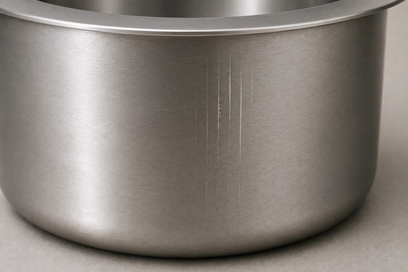
표면의 선형 자국도 별도로 분류합니다. 금형에 달라붙은 소재가 긁고 지나간 스코어링, 페라이트계 스테인리스의 압연 방향 리징·로핑은 외관상 물결처럼 보일 수 있지만 거시적인 플랜지 좌굴과는 다릅니다. 세척 후 확대 관찰과 단면·형상 측정을 함께 사용하면 실제 파형, 긁힘, 재료 표면 특성을 구별하는 데 도움이 됩니다.
블랭크 홀더 하중과 공정창
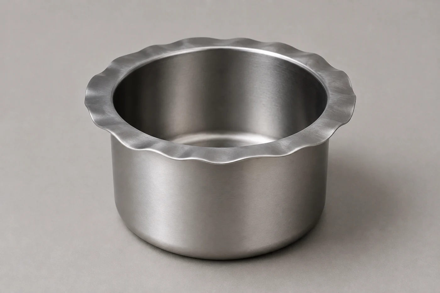
블랭크 홀더는 플랜지를 지지하면서 다이 안으로 들어가는 소재의 흐름을 제어합니다. 홀더 하중이 부족하면 원주 압축을 받는 판재가 들뜨고 주름이 자라기 쉽습니다. 하중을 높이면 좌굴을 억제할 수 있지만 접촉면의 마찰 저항도 커져, 벽을 만드는 데 필요한 소재 공급이 부족해질 수 있습니다.
주름이 발생하지 않는 최소 구속과 균열이 시작되는 최대 구속 사이가 실무적으로 검토할 공정창입니다. 이 범위는 홀더 하중 하나로 고정되지 않으며 블랭크 크기, 판 두께, 금형 반경, 윤활과 재료 특성이 함께 결정합니다. 예를 들어 윤활 조건을 바꾸면 같은 홀더 하중에서도 유입 저항이 달라지므로 기존 하중 설정만 그대로 유지해서는 결과를 보장하기 어렵습니다.
하중과 압력은 구분해서 기록해야 합니다. 홀더 총하중은 N 또는 kN으로 표현하며, 소재 접촉면의 평균 압력은 그 하중을 실제 접촉 면적으로 나눈 값입니다. 성형 중 플랜지 면적이 줄면 총하중이 일정해도 평균 압력이 달라질 수 있으며, 유압 회로의 압력 표시값이 곧 소재에 작용하는 균일한 압력을 의미하지도 않습니다.
홀더의 접촉 상태는 총하중만큼 중요합니다. 금형의 평행도, 패드와 지지점의 배치, 탄성 변형, 판 두께 차이 때문에 한쪽에서 먼저 닿거나 특정 구역에 하중이 몰릴 수 있습니다. 한쪽 코너에서는 주름이 생기고 반대편 벽에서는 균열이 발생한다면 전체 하중을 일괄 변경하기 전에 방향별 유입량과 접촉 분포를 확인하는 편이 원인을 좁히는 데 효과적입니다.
스트로크에 따라 홀더 하중을 바꾸거나 다점 쿠션으로 구역별 하중을 조정하면 소재 유입을 더 세밀하게 제어할 수 있습니다. 다만 초기에는 높이고 후기에는 낮추는 식의 일정한 패턴이 모든 제품에 맞는 것은 아닙니다. 주름이 시작되는 스트로크와 벽의 감육이 빠르게 증가하는 구간을 먼저 파악하고, 실제 쿠션의 응답과 하중 유지 능력에 맞추어 하중 경로를 설계해야 합니다.
조건 시험에서는 주름 유무뿐 아니라 최소 두께, 유입량과 균열 위치를 함께 비교합니다. 한 설정에서 불량이 사라졌더라도 인접 조건에서 바로 반대 불량이 생기면 양산 여유가 작다는 뜻입니다. 정상적인 소재·윤활 변동을 포함해 허용 영역을 확인하고, 두 한계가 겹쳐 여유가 없으면 블랭크와 금형 또는 성형 단계의 변경으로 검토 범위를 넓혀야 합니다.
블랭크 형상과 드로잉비
블랭크 크기는 제품의 완성 높이만 보고 정하기 어렵습니다. 바닥과 벽에 필요한 면적 외에도 실제 코너 반경, 남겨 둘 플랜지, 이어링과 트리밍 여유를 포함해야 합니다. 블랭크를 크게 하면 공급 가능한 소재는 늘지만, 끌어와야 할 플랜지도 커져 인장 하중과 원주 압축의 부담이 함께 달라집니다.
면적 보존은 초기 크기를 가늠하는 유용한 출발점입니다. 다음 계산은 평균 지름 50 mm, 벽 높이 40 mm인 바닥이 있는 원통 컵을 가정하고 두께 변화와 코너 반경, 트리밍 여유를 생략한 예시입니다. 계산된 블랭크 지름은 실제 금형에 투입할 치수를 확정한 결과가 아닙니다.
| 계산 항목 | 예시 결과 | 기하학적 의미 |
|---|---|---|
| 바닥 면적 | 약 1,963.5 mm² | 평균 지름 50 mm인 원의 면적 |
| 벽 면적 | 약 6,283.2 mm² | 평균 둘레에 벽 높이 40 mm를 곱한 면적 |
| 합계 면적 | 약 8,246.7 mm² | 바닥과 벽에 필요한 면적의 합 |
| 등면적 원형 블랭크 | 지름 약 102.5 mm | 두께 변화·반경·트림 여유를 제외한 초기 추정 |
평균 지름은 판 두께 가운데 면을 기준으로 한 기하학적 치수이며 펀치 지름과 같지 않을 수 있습니다. 실제 전개에서는 곡면과 남는 플랜지, 성형 중 두께 분포를 반영하고 시험품의 가장자리 위치로 보정합니다. 트리밍 여유를 과도하게 남기면 재료비가 증가하고, 반대로 지나치게 줄이면 높이 부족이나 특정 방향의 소재 공급 부족이 발생할 수 있습니다.
드로잉비와 국부 소재 공급
드로잉비는 원형 블랭크 지름을 펀치 지름으로 나눈 값입니다. 한계 드로잉비인 LDR은 정해진 시험 조건에서 파단 없이 성형할 수 있었던 최대 블랭크에 대한 비율이므로 현재 제품의 드로잉비와 구별해야 합니다. 어느 재료의 시험 LDR보다 계산값이 작다는 이유만으로 실제 제품의 모든 코너와 벽이 안전하다고 판단할 수는 없습니다.
시험 LDR에는 판 두께, 재료 상태, 윤활, 홀더 하중과 금형 반경이 영향을 줍니다. 특히 사각 컵, 높이가 다른 벽, 비대칭 플랜지에서는 국부적인 유입 경로가 전체 지름비보다 중요해질 수 있습니다. 이런 형상은 원통 컵 지표로 소재를 1차 비교하되, 실제 형상에 대한 유입량과 두께 분포로 공정 가능성을 판단해야 합니다.
블랭크 외곽은 방향별 소재 공급을 조절하는 설계 변수이기도 합니다. 주름이 생기는 코너의 여유 면적과 균열이 생기는 벽의 공급 경로를 함께 검토하면 홀더 하중만 바꿀 때보다 넓은 공정창을 확보할 가능성이 있습니다. 변경 전후에는 동일한 기준점에서 남은 플랜지와 유입량을 비교하고, 블랭크 방향·중심 위치와 트리밍 기준을 도면에 연결해 관리합니다.
재료의 r값·n값과 방향성
재료의 인장강도와 연신율만으로 딥드로잉 적합성을 판단하면 중요한 차이를 놓칠 수 있습니다. 컵 벽이 얇아지는 것을 견디는 능력, 변형을 넓게 분산하는 능력, 절단면이 늘어날 때 갈라지지 않는 능력은 서로 다릅니다. 제품에서 어떤 변형이 지배적인지 먼저 정해야 필요한 재료 특성과 시험 항목을 선택할 수 있습니다.
r값은 인장시험 중 폭 방향의 진소성 변형률을 두께 방향의 진소성 변형률로 나눈 값입니다. 평균 r값이 높으면 일반적으로 두께가 변하는 방향보다 판면 안에서 변형하려는 경향이 커져 컵 드로잉에 유리합니다. 그러나 실제 벽의 두께는 방향별 강도와 유입 조건의 영향도 받으므로 r값 하나로 최종 감육 위치를 확정하지는 않습니다.
압연 방향을 기준으로 0°·45°·90°에서 측정한 r값은 평균적인 두께 변화 저항과 평면 안의 방향 차이를 구분하는 데 사용합니다. 평균 r값이 충분히 높아도 방향 차이가 크면 이어링과 트리밍 손실이 문제가 될 수 있습니다. 세 방향으로 계산한 평면 이방성 지표가 작더라도 복잡한 제품의 모든 방향에서 흐름이 완전히 같다는 의미는 아닙니다.
n값은 소성 변형이 진행될 때 재료가 얼마나 가공경화하는지를 나타냅니다. 먼저 많이 늘어난 부분이 더 강해지면 후속 변형이 주변으로 분산되어 급격한 국부 감육을 늦추는 데 도움이 됩니다. 따라서 바닥이 늘어나는 형상이나 돌출부가 있는 제품에서는 n값과 성형한계도 중요하며, r값이 우수하다는 이유로 이 검토를 생략하기 어렵습니다.
물성 시험과 재료 대체
r값과 n값은 측정 방향과 평가 변형 구간을 함께 봐야 비교할 수 있습니다. 같은 강종명이라도 공급 상태와 제조 이력에 따라 가공경화 거동이 다를 수 있고, 이미 전 공정에서 변형된 재료는 초기 소재와 같지 않습니다. 특히 알루미늄은 합금 번호와 조질, 스테인리스는 강종과 냉간가공 상태를 분리해서 확인해야 합니다.
재료군의 차이도 성형 방식에 맞추어 해석합니다. 오스테나이트계 스테인리스의 늘어나는 성형 능력과 페라이트계의 순수 드로잉 특성은 같은 기준으로 순위를 매기기 어렵습니다. 고강도 소재에서는 프레스 하중과 스프링백뿐 아니라 작은 반경·절단면의 국부 파단 가능성을 함께 검토하며, 표면 품질이 중요한 부품은 리징과 같은 재료 특성도 구매 조건에 포함합니다.
입고 성적서에 r값·n값이나 성형한계곡선이 항상 포함되는 것은 아닙니다. 요구 성형 깊이와 형상의 위험에 맞추어 추가 자료 또는 시험을 협의하고, 시험편 방향·두께·평가 구간을 확인합니다. 재료 대체를 승인할 때는 강도와 연신율의 합격 여부에 더해 실제 유입량, 최소 두께와 결함 위치가 기존 승인 조건에서 유지되는지 검증해야 합니다.
펀치·다이 반경과 편측 간극
다이 어깨 반경은 판재가 플랜지에서 벽으로 넘어가는 경로를 만듭니다. 반경이 작아지면 굽힘과 펴짐이 급해져 필요한 하중과 국부 변형의 부담이 커질 수 있습니다. 펀치 반경은 바닥과 벽의 연결 형상을 만들기 때문에, 이 부위에서 재료가 받는 인장과 굽힘을 함께 검토해야 합니다.
반경을 크게 하는 조정에도 한계가 있습니다. 다이 입구 부근의 지지 조건과 접촉 영역이 달라져 소재가 과도하게 유입되거나 지지되지 않는 구간에서 주름이 생길 수 있습니다. 요구되는 제품 반경과 바닥 형상까지 바뀔 수 있으므로, 작은 반경의 균열을 줄이는 효과와 전체 유입 균형을 함께 평가합니다.
금형 간극은 편측 값인지 지름 차이인지 먼저 명확히 해야 합니다. 원통 금형에서는 다이 내경과 펀치 외경의 차이를 절반으로 나눈 값이 편측 간극입니다. 도면과 검사 성적서에서 이 정의가 다르면 실제보다 두 배 크거나 작은 간극으로 이해할 수 있으므로, 측정 위치와 공차까지 같은 기준으로 기록합니다.
간극은 최초 판 두께만 기준으로 판단하기 어렵습니다. 플랜지는 원주 압축으로 두꺼워질 수 있으며, 그 소재가 벽으로 들어올 때 간극보다 두꺼우면 두께를 눌러 줄이는 아이어닝이 발생합니다. 의도하지 않은 아이어닝은 하중과 접촉 상태를 바꾸므로, 드로잉 자체의 저항 증가와 구분해야 합니다.
실험 사례에서는 AA5754-O 알루미늄 1.0 mm 판재와 지름 60 mm 블랭크를 사용하고, 홀더 하중 6 kN·펀치 속도 1.1 mm/s의 상온 윤활 조건을 적용했습니다. 실제 편측 간극은 1.15 mm였지만 플랜지 최대 두께가 1.3 mm까지 증가해 후반에 아이어닝이 발생했습니다. 이 결과는 특정 컵 금형의 관찰이며, 1.15 mm를 다른 소재와 제품의 권장 간극으로 사용할 근거는 아닙니다.
현장에서는 펀치와 다이의 실제 치수, 모서리 반경, 동심도와 마모 상태를 확인하고 두꺼워지는 영역의 측정값을 대조합니다. 코팅·연마·수리 이후에는 표면 상태뿐 아니라 형상과 간극도 달라질 수 있습니다. 한쪽 벽만 얇아지거나 특정 방향에 긁힘이 반복되면 공칭 간극 전체를 바꾸기 전에 편심과 국부 접촉을 확인해야 합니다.
최종 제품에 작은 코너 반경이나 균일한 벽 두께가 필요하다면, 초기 드로잉과 후속 형상 정리의 역할을 나누는 방안을 검토할 수 있습니다. 다만 후속 공정에서도 남은 성형 능력과 두께 분포를 확인해야 하며, 아이어닝을 의도적으로 적용할 경우에는 목표 두께와 하중·윤활 조건을 별도로 설정해야 합니다.
윤활·속도·온도의 상호작용
윤활은 긁힘을 줄이는 보조 작업을 넘어 소재 유입을 결정하는 공정 변수입니다. 홀더와 다이 쪽의 마찰이 바뀌면 같은 하중에서도 플랜지가 들어오는 양이 달라집니다. 펀치와의 접촉 역시 변형 분포에 영향을 주기 때문에, 전체 면을 같은 방식으로 더 미끄럽게 만드는 조정이 항상 유리하지는 않습니다.
윤활제를 비교할 때는 제품명뿐 아니라 도포량과 분포, 희석액의 관리 상태, 판재 표면과 금형 상태를 함께 맞추어야 합니다. 손으로 충분히 바른 시험품과 자동 도포 장치로 생산한 제품은 같은 윤활 조건으로 보기 어렵습니다. 필요한 구역의 윤활 부족과 한쪽으로 치우친 도포를 구분하려면 표면의 실제 분포와 방향별 유입량을 연결해서 확인합니다.
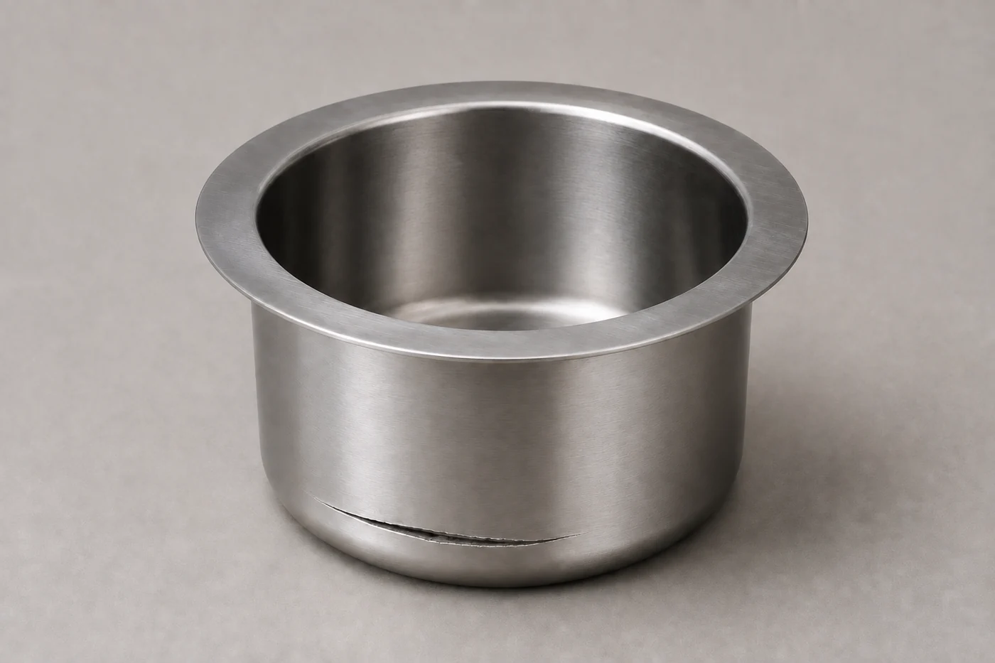
접촉 압력이 높은 다이 어깨에서는 윤활막이 부족해지거나 금형에 소재가 달라붙는 갤링이 발생할 수 있습니다. 부착된 소재가 이후 제품을 긁으면 표면 손상과 마찰 증가가 함께 진행되어, 처음에는 양품이던 조건에서도 벽의 감육이나 균열이 나타날 수 있습니다. 따라서 반복되는 긁힘의 위치, 금형 부착물과 하중 변화는 같은 시간축에서 비교하는 것이 좋습니다.
생산 속도를 높이면 변형 속도와 접촉 시간이 바뀌고, 반복 성형으로 판재와 금형의 온도가 올라갈 수 있습니다. 온도는 윤활제의 점도와 막 유지 능력, 재료의 변형 거동에 영향을 주므로 저속 시험의 결과를 목표 생산 속도에 그대로 적용하기 어렵습니다. 반대로 속도를 낮춘다고 모든 균열이 줄어드는 것도 아니며, 실제 불량과 연결된 온도·마찰·변형 변화가 무엇인지 확인해야 합니다.
조건 검증에는 냉간 시동 직후와 연속 생산으로 온도가 안정된 구간을 모두 포함합니다. 프레스 속도, 금형 또는 제품의 측정 온도, 윤활 공급 상태, 하중 이력과 결함 발생 순서를 함께 기록하면 열에 따른 변화를 구분하기 쉽습니다. 특정 생산 매수 뒤에 불량이 늘어난다면 재료 로트 변화와 함께 윤활 고갈, 오염·부착과 열 축적을 우선 비교합니다.
윤활 선정은 후공정과도 연결됩니다. 성형에는 적합해도 세척 잔류물이 접착·용접·도장 또는 도금에 영향을 주면 전체 공정 비용이 늘어날 수 있습니다. 소재·표면처리와의 적합성, 보관 후 제거 가능성, 재도포 주기와 관리 방법을 확인하고, 변경 승인은 성형 외관뿐 아니라 관련 후공정의 결과까지 포함해 판단합니다.
다단 드로잉과 공정 설계
주름을 막는 조건에서 균열이 나고, 균열을 막는 조건에서는 주름이 남는다면 한 단계의 조정만으로 확보할 수 있는 여유가 부족할 수 있습니다. 이때는 초기 드로잉의 깊이와 형상, 재드로잉, 최종 형상 정리의 역할을 나누어 검토합니다. 목적은 각 단계에서 필요한 소재 유입과 국부 변형을 감당할 수 있는 범위로 배분하는 것입니다.
재드로잉은 이미 만든 컵의 지름과 깊이를 다시 바꾸는 공정입니다. 이전 단계에서 발생한 가공경화, 두께 차이와 방향성은 다음 단계의 출발 조건으로 남습니다. 전체 형상을 여러 번으로 나누었다고 매번 새 판재와 같은 성형 능력이 생기는 것은 아니므로, 공정 사이의 형상뿐 아니라 물성·두께·변형 이력을 함께 전달해야 합니다.
처음에는 소재를 충분히 유입시키고 후속 공정에서 코너와 치수를 정리하는 방식이 도움이 될 수 있습니다. 그러나 예비 형상에 소재가 잘못 배분되면 다음 공정에서 접힘이나 과도한 늘어남이 새로 발생할 수 있습니다. 최종 제품만 검토하지 말고 중간 컵의 깊이, 지름, 가장자리 높이와 벽 두께를 승인 항목으로 정해야 합니다.
아이어닝은 벽 두께를 줄이는 기능을 가진 공정이므로 일반 드로잉과 목적을 구분합니다. 목표 두께를 일정하게 만들거나 벽을 더 길게 만드는 데 활용할 수 있지만, 그만큼 두께 방향 압축과 접촉 저항을 견디는 금형·윤활 조건이 필요합니다. 금형 간극이 좁아 우연히 발생한 아이어닝을 제품 두께 관리 공정으로 간주해서는 안 됩니다.
중간 열처리는 재료의 조질과 요구 성능에 맞추어 별도로 검토할 선택지입니다. 가공경화를 완화하는 효과만 보고 적용하면 최종 강도, 표면 산화와 세척, 치수 변화 또는 소재에 따른 열처리 반응을 놓칠 수 있습니다. 합금·강종별로 허용되는 조건과 후속 공정의 영향을 검증해야 하며, 한 재료의 어닐링 온도와 시간을 다른 재료에 옮겨 쓰지 않습니다.
공정 해석에서도 각 단계의 변형 이력이 중요합니다. 일반적인 변형률 기반 성형한계곡선은 비례적인 면내 변형률 경로를 전제로 하므로, 재드로잉이나 굽힘·펴짐이 반복되는 위치의 위험을 단순히 한 곡선과 비교하는 데 한계가 있습니다. 이력을 반영할 수 있는 재료 모델과 적절한 파단·네킹 판정 방법을 사용하고, 중간 및 최종 시험품으로 결과를 확인해야 합니다.
단계를 늘리면 금형, 이송과 검사 부담이 증가합니다. 반면 한 단계에서 지나치게 좁은 조건을 유지하는 데 드는 불량·재조정 비용을 줄일 가능성도 있습니다. 선택 기준은 정해진 생산 수량 하나가 아니라 요구 형상, 공정 여유, 재료 이용률, 후공정 품질과 실제 설비에서의 반복성입니다.
불량 위치별 진단과 조건 조정
원인 분석은 불량품만 따로 보는 것보다 직전·직후 양품과 함께 비교할 때 효과적입니다. 소재 로트와 블랭크 방향, 중심 위치, 윤활 상태, 발생 시점이 같았는지 먼저 정리합니다. 결함 위치는 제품 기준면과 압연 방향에 연결해 표시하고, 하사점 이전에 생긴 것인지 이형·트리밍 과정에서 발생한 것인지 구분합니다.
균열에는 형태와 두께의 증거가 필요합니다. 바닥 연결부에 얇은 띠가 생겼다면 같은 방향의 유입량이 줄었는지 확인하고, 절단면에서 시작했다면 버와 미세 균열, 절단 공구 상태와 변형 방향을 대조합니다. 이미 찢어진 부분만 측정하면 파단 직전의 두께를 알기 어려우므로 인접 양품과 중간 스트로크별 시험품이 원인 확인에 도움이 됩니다.
| 반복되는 현상 | 확인할 증거 | 조정 방향과 확인 사항 |
|---|---|---|
| 한쪽 플랜지 주름·반대쪽 벽 균열 | 방향별 유입량, 중심 위치, 홀더 접촉 | 편심·하중 편차를 보정하고 두 결함을 동시에 재평가 |
| 바닥 코너의 감육·찢어짐 | 코너 두께 분포, 실제 반경, 소재 공급량 | 유입 저항과 형상 부담을 검토하며 플랜지 주름도 확인 |
| 벽의 접힘과 후반 하중 상승 | 플랜지 주름의 시작 시점, 후육, 실제 간극 | 주름 유입과 아이어닝을 구분해 최초 발생 원인을 조정 |
| 절단 가장자리의 균열 | 절단면 손상, 버 방향, 네킹 유무 | 절단 품질·국부 성형성·굽힘 조건을 함께 검토 |
| 생산이 진행될수록 긁힘·균열 증가 | 온도, 윤활 공급, 금형 부착물, 하중 추이 | 열·마찰 변화와 소재 로트 변화를 분리해 검증 |
유입량·하중과 조정 기준
다이 안으로 들어간 양인 유입량은 소재 흐름을 직접 비교하는 지표입니다. 블랭크 외곽의 기준 위치를 정하고, 동일한 스트로크에서 남은 가장자리 위치가 얼마나 이동했는지 방향별로 기록합니다. 블랭크 크기나 측정 기준이 달라진 시험을 그대로 비교하면 실제 흐름의 차이와 초기 형상의 차이가 섞이므로 기준을 통일해야 합니다.
하중 곡선은 원인을 찾는 단서로 사용합니다. 후반 하중이 높아졌다고 바로 홀더 과하중으로 판단할 수는 없으며, 두꺼워진 소재의 아이어닝이나 주름의 접힘, 갤링도 곡선을 바꿀 수 있습니다. 최대 하중 숫자 하나보다 상승이 시작된 스트로크를 형상·두께·유입량과 맞추어 보는 것이 중요합니다.
조건 조정은 먼저 불량이 특정 방향과 위치에 고정되는지, 전체 둘레에서 나타나는지 구분한 뒤 진행합니다. 중심 어긋남이나 국부 마모를 확인하지 않은 상태에서 전체 홀더 하중과 윤활을 바꾸면 다른 구역의 양품 조건까지 움직일 수 있습니다. 초기에는 주요 변수를 분리해 영향을 확인하고, 이후에는 홀더 하중·윤활·블랭크의 상호작용을 포함한 시험 조합으로 허용 범위를 정리합니다.
조정 전후의 합격 기준도 같아야 합니다. 눈에 띄는 균열이 사라져도 최소 두께가 부족하거나 트리밍 뒤 높이가 모자라면 해결된 조건으로 승인할 수 없습니다. 반대로 기능과 후공정에 영향을 주지 않는 위치의 외관 요구를 과도하게 강화하면 불필요하게 공정창을 좁힐 수 있으므로, 도면의 기능 요구와 외관 판정을 분명히 구분합니다.
두께·유입량 검사와 양산 승인
완성품의 외관만으로 딥드로잉 품질을 승인하기 어렵습니다. 바닥에서 펀치 반경을 지나 벽과 가장자리로 이어지는 두께 분포, 방향별 유입량, 균열·주름과 최종 형상을 함께 확인해야 합니다. 가장 얇은 위치가 항상 측정하기 쉬운 입구에 있지는 않으므로, 해석과 시험으로 찾은 위험 위치를 검사 계획에 포함합니다.
두께 측정은 제품 형상에 맞는 방법을 사용합니다. 양면 접근이 가능한 부위는 적합한 접촉 측정으로 확인하고, 작은 반경이나 접근이 어려운 위치는 절단 시편 또는 검증된 광학 측정 등을 검토합니다. 측정 방향·위치·간격과 측정력을 정하고, 감육이 급해지는 구간에서는 점 사이의 최저값을 놓치지 않도록 간격을 세분화해야 합니다.
| 관리 항목 | 측정·기록 내용 | 판정에 연결할 요구 |
|---|---|---|
| 두께 분포 | 초기 두께와 위치별 최종 두께, 최소 위치, 방향 | 도면의 최소 잔여 두께와 기능 요구 |
| 유입량 | 동일 스트로크의 방향별 가장자리 이동량 | 승인된 흐름의 범위와 좌우·코너 균형 |
| 하중 이력 | 펀치·홀더의 실제 하중과 스트로크, 반복 변화 | 승인 곡선의 범위와 이상 발생 구간 |
| 결함·표면 | 균열 시작점, 주름 높이·위치, 긁힘과 부착 | 기능면·외관면별 허용 기준 |
| 최종 형상 | 이형 후 높이·원형도·윤곽, 트리밍 후 치수 | 조립 기준과 자유 상태 또는 지정 지지 상태 |
| 재료·생산 조건 | 로트, 방향, 속도, 온도, 윤활과 공정 이력 | 승인 조건의 적용 범위와 변경 관리 |
감육률은 초기 측정 두께에 비해 얼마나 얇아졌는지 나타내는 결과값입니다. 특정 감육률 이하라는 이유만으로 합격을 정하기보다 하중 지지, 밀봉, 부식 여유와 조립 기능에서 필요한 최소 두께를 먼저 정해야 합니다. 측정 반복성과 위치 재현성이 부족하면 공정 변동과 측정 오차를 구분할 수 없으므로, 경계값에 가까운 판정일수록 측정 방법의 적합성을 확인합니다.
성형한계와 양산 검증
성형한계곡선인 FLC와 변형률 분포를 겹쳐 보는 FLD는 네킹 위험을 찾는 데 유용합니다. 그러나 작은 반경과 절단면의 국부 파단, 주름 좌굴까지 하나의 곡선으로 판정할 수는 없습니다. 격자나 DIC로 측정한 표면 변형률에는 굽힘과 공간 해상도의 영향도 있으므로, 해당 두께·재료 상태의 곡선과 적절한 측정·해석 조건을 함께 확인해야 합니다.
성형 해석은 최대 하중 하나가 맞는지만 비교해서 승인하지 않습니다. 방향별 유입량, 두께 분포, 이어링과 결함의 위치·발생 시점까지 시험품과 대조하고, 마찰·물성·접촉·격자 크기를 바꾸었을 때 판단이 얼마나 달라지는지 확인합니다. 특히 주름은 대칭을 강제한 모델에서 억제될 수 있으므로 실제로 가능한 좌굴 형태를 해석 모델이 허용하는지도 검토해야 합니다.
양산 승인은 목표 속도와 정상적인 윤활 공급, 냉간 시동 및 온도 안정 구간, 예상되는 소재 로트 변동을 포함해 진행합니다. 도면에는 재질·조질·두께 공차, 반경과 기준면, 최소 잔여 두께, 주름·균열·외관 판정, 트리밍 후 치수와 측정 상태를 연결해야 합니다. 승인된 하중·유입량 범위에서 벗어났을 때 확인할 항목과 재료·금형·윤활 변경 시 재검증할 범위도 함께 정합니다.
제작 협의에는 최종 도면뿐 아니라 사용 기능, 후공정과 검사 기준을 함께 전달하는 것이 도움이 됩니다. 프레스 가공 검토에서는 초기 블랭크부터 성형·트리밍까지의 역할을 연결하고, 제작 문의에는 균열과 주름의 위치, 두께 측정값과 발생 조건을 포함하면 원인 검토에 필요한 정보를 구체화할 수 있습니다. 성형 조건의 완성도는 결함을 잠시 없앤 결과보다, 필요한 기능과 치수를 반복해서 만족하는 범위로 판단해야 합니다.
English Technical Overview
In deep drawing, increasing blankholder force to suppress wrinkles can split the wall. Lowering the force to reduce cracking can then produce flange wrinkles. Both defects can alternate when the force pulling the sheet into the die and the resistance controlling its entry are out of balance. Diagnosis begins by locating the first defect and when it appears, then checking actual material draw-in and the regions that have thinned.
A stable stamping process needs more latitude than a setting that produces one complete part. It needs enough margin to prevent cracking, wrinkling and dimensional defects across normal production variation in sheet gauge, material properties, lubrication and tool temperature. The blank, tooling, material and inspection criteria must be considered together to establish and maintain that margin.
Material Draw-In and Deformation Regions
Deep drawing forms a flat sheet blank into a cup or box using a punch and die. As the punch descends, material from the outer flange passes through the die entry and becomes the wall. The essential mechanism is supplying wall area from the surrounding sheet, rather than obtaining all the depth by continually stretching the bottom.
The flange is pulled radially while being compressed circumferentially. Material originally lying on a larger circumference must accommodate a smaller circumference as it moves inward. If the sheet cannot accommodate this compression while remaining flat, it buckles out of plane and forms flange wrinkles.
The wall transmits force from the punch to the flange. A higher force requirement for drawing in material can concentrate tensile demand near the wall-to-bottom transition. Localized thinning, or necking, reduces the load-bearing section, further concentrates deformation and can eventually produce a tear.
At the die shoulder, the sheet bends from a flat region around a curved surface and then straightens into the wall. Resistance here therefore includes the force needed for bending and straightening as well as friction. Deformation over a flat punch bottom may be relatively small. A domed bottom or raised feature also requires the stretching in that region to be evaluated.
Material flow differs between the corners and straight walls of a rectangular part. Corner flanges undergo circumferential contraction similar to a cylindrical cup. Along straight sections, bending and straightening over the die shoulder account for a substantial part of the flow. Equal restraint around the perimeter can therefore leave excess material at a corner while starving a particular wall.
Process review becomes clearer when divided into blank placement, holder contact, initial bending, sustained draw-in, final shape formation near bottom dead center, and ejection and trimming. Identifying the contact and deformation introduced at each stage helps locate the initiating cause. The largest wrinkle or longest crack on the finished part does not necessarily identify where the defect began.
Distinguishing Cracks, Wrinkles and Earing
Accurate classification guides the remedy. A wall crack following thinning and one starting at a cut edge can represent different failures. Flange buckling also differs from earing, where rim height varies with direction.
First examine the thickness, section and surface condition around the crack origin. If a broad region has thinned before deformation concentrates into a narrow band, investigate restricted material supply and necking. If a cut edge or tight bend cracks with little visible necking, cutting damage, local deformation capacity and bending conditions provide more direct clues.
| Defect type | Main observable features | First distinctions to establish |
|---|---|---|
| Wall-to-bottom transition crack | Tearing accompanied by a thin band or reduced section | Insufficient draw-in, excessive restraint, concentrated stretching |
| Cut-edge or bend crack | Starts at an edge or small radius; necking may be limited | Cutting damage, directionality, local formability |
| Flange wrinkles | Repeated out-of-plane buckling beneath the holder | Circumferential compression, support and holder contact |
| Wall wrinkles | Waves or fold marks remaining in the wall | Imported flange wrinkles versus new buckling in the wall |
| Earing | Periodic variation in cup rim height around the perimeter | Material planar anisotropy and blank orientation |
Wrinkles visible in the wall require further investigation of their origin. Waves formed in the flange may have been pulled through the die and left in the wall. Alternatively, compressive loading may create new wrinkles in an insufficiently supported wall region. Modifying only the wall geometry can leave the initiating cause unresolved if wrinkling began beneath the holder.
Earing can arise because directional differences in plastic deformation produce uneven material flow relative to the rolling direction. Evaluate directional properties, blank orientation and trim allowance rather than relying on increased holder force to equalize the rim. However, strongly asymmetric height variation also requires checks for off-center placement and uneven contact.
Classify linear surface marks separately as well. Scoring from material adhering to the die and rolling-direction ridging or roping in ferritic stainless steel can resemble waves. They differ from macroscopic flange buckling. Magnified examination after cleaning, combined with section and profile measurements, helps distinguish actual waves, scratches and material-related surface features.
Blankholder Force and the Process Window
The blankholder supports the flange while controlling material entering the die. Insufficient force allows sheet under circumferential compression to lift and develop wrinkles. More force can suppress buckling, but it also increases frictional resistance at the contact surfaces and can restrict the material needed to form the wall.
The process window lies between the minimum restraint preventing wrinkles and the maximum before cracking. Blank size, gauge, tool radii, lubrication and material properties determine this range with holder force. Changing lubrication changes flow resistance at the same force, so retaining the setting does not ensure the same result.
Record force and pressure separately. Total holder force is expressed in N or kN. Average pressure on the sheet is that force divided by the actual contact area. As the flange area decreases during forming, average pressure can change even at constant total force. Hydraulic circuit pressure is also not equivalent to uniform pressure acting on the sheet.
Holder contact is as important as total force. Tool parallelism, pad and support layout, elastic deflection and gauge variation can cause one side to contact first or concentrate loading in a particular area. If one corner wrinkles while the opposite wall splits, comparing directional draw-in and contact distribution helps narrow the cause before changing the overall force.
Force can be varied with stroke, or a multipoint cushion can adjust loading by region, to provide finer control of material flow. However, a fixed pattern such as high force early and low force late does not suit every part. Identify when wrinkles begin and when wall thinning accelerates. Then design the force trajectory around those observations and the actual cushion response and force-maintaining capability.
Trials should compare minimum thickness, draw-in and crack location alongside the presence of wrinkles. If a defect disappears at one setting but the opposite defect occurs immediately at a neighboring setting, production margin is limited. Establish the acceptable region with normal material and lubrication variation included. If the limits overlap and leave no margin, extend the review to blank design, tooling or the number of forming stages.
Blank Shape and Drawing Ratio
Blank size cannot be established from finished part height alone. In addition to the area required for the bottom and wall, it must account for actual corner radii, any retained flange, earing and trim allowance. A larger blank supplies more material, but also creates a larger flange to draw in, changing both tensile demand and circumferential compression.
Area conservation provides a useful initial estimate. The following example assumes a closed-bottom cylindrical cup with a mean diameter of 50 mm and a wall height of 40 mm. It omits thickness changes, corner radii and trim allowance. The calculated blank diameter does not establish the final size for the actual tooling.
| Calculation item | Example result | Geometric meaning |
|---|---|---|
| Bottom area | Approximately 1,963.5 mm² | Area of a circle with a 50 mm mean diameter |
| Wall area | Approximately 6,283.2 mm² | Mean circumference multiplied by the 40 mm wall height |
| Combined area | Approximately 8,246.7 mm² | Total area required for the bottom and wall |
| Equal-area circular blank | Approximately 102.5 mm diameter | Initial estimate excluding thickness changes, radii and trim allowance |
Mean diameter is a geometric dimension at the sheet mid-thickness and may differ from punch diameter. Actual blank development should include curved surfaces, any remaining flange and thickness redistribution, followed by correction using the edge positions of trial parts. Excessive trim allowance increases material cost. Too little can leave insufficient height or inadequate material supply in a particular direction.
Drawing Ratio and Local Material Supply
Drawing ratio is the circular blank diameter divided by the punch diameter. The limiting drawing ratio, or LDR, uses the largest blank successfully drawn without fracture under defined test conditions. It must therefore be distinguished from the drawing ratio of the current part. A calculated ratio below a material’s test LDR does not establish that every corner and wall of the actual product is safe.
Test LDR is influenced by gauge, material condition, lubrication, holder force and tool radii. Local flow paths can be more important than an overall diameter ratio for rectangular cups, unequal wall heights and asymmetric flanges. A cylindrical cup index can help with initial material comparisons, but feasibility should be judged from draw-in and thickness distribution in the actual geometry.
The blank outline is also a design variable for directional material supply. Reviewing excess area near a wrinkling corner together with the supply path to a splitting wall may provide a wider process window than adjusting holder force alone. Compare remaining flange and draw-in from the same reference points before and after a change. Link blank orientation, center position and trimming references to the drawing and control plan.
Material r-Value, n-Value and Directionality
Judging deep-drawing suitability from tensile strength and elongation alone can miss important differences. Resistance to wall thinning, the ability to distribute deformation and resistance to cracking at a stretched cut edge are different capabilities. Identify the dominant deformation modes in the part before selecting the required material properties and tests.
The r-value is the ratio of true plastic width strain to true plastic thickness strain during a tensile test. A higher mean r-value generally indicates a greater tendency to deform within the sheet plane rather than change thickness, which benefits cup drawing. However, directional strength and material-flow conditions also affect actual wall thickness. The r-value alone does not determine where maximum thinning will occur.
Values measured at 0°, 45° and 90° to the rolling direction help distinguish average resistance to thickness change from directional variation within the plane. Even with a sufficiently high mean r-value, substantial directional variation can cause earing and trim losses. A small planar anisotropy index calculated from three directions does not mean that material flow is identical in every direction of a complex part.
The n-value describes strain hardening as plastic deformation progresses. A region that stretches more initially becomes stronger, helping distribute subsequent deformation into surrounding material and delaying severe localized thinning. Consequently, parts with stretching bottoms or raised features also require consideration of n-value and forming limits. A favorable r-value does not remove that need.
Property Testing and Material Substitution
Compare r-values and n-values together with measurement direction and the strain interval used for evaluation. Even the same grade designation can exhibit different hardening behavior with supply condition and manufacturing history. Material deformed in an earlier operation also differs from the original sheet. In particular, verify both alloy designation and temper for aluminum, and both grade and cold-worked condition for stainless steel.
Material-family differences must also be interpreted in relation to the forming mode. Austenitic stainless steel’s stretching capability and ferritic stainless steel’s pure-drawing characteristics cannot be ranked on a single scale. For high-strength material, evaluate local fracture at tight radii and cut edges alongside press force and springback. Material-related features such as ridging should also be specified when surface quality matters.
Incoming material certificates do not always include r-value, n-value or a forming-limit curve. Agree on additional data or testing according to the risks associated with draw depth and geometry. Check specimen orientation, thickness and the evaluation interval. When approving a substitute material, verify that actual draw-in, minimum thickness and defect locations remain acceptable under the approved process conditions, in addition to checking strength and elongation.
Punch and Die Radii and Radial Clearance
The die shoulder guides material from flange to wall. A smaller radius intensifies bending and straightening, potentially increasing force and local deformation. The punch radius forms the wall-to-bottom transition, where tension and bending must be assessed together.
Increasing a radius changes die-entry support and contact, potentially allowing excess inflow or wrinkles in unsupported regions. It may also change the required product radius and bottom shape. Assess crack reduction at tight radii together with overall flow balance.
First establish whether a specified clearance is radial, on one side, or the diametral difference. For cylindrical tooling, radial clearance is half the difference between die bore diameter and punch outside diameter. Different definitions in drawings and inspection reports can result in a clearance being understood as twice or half its actual value. Use the same convention, measurement locations and tolerances throughout.
Initial gauge alone cannot determine clearance. Circumferential compression can thicken the flange. As material thicker than the gap enters the wall, ironing reduces its thickness. This unintended operation changes force and contact conditions; distinguish it from increased drawing resistance.
One experiment used 1.0 mm AA5754-O aluminum with a 60 mm blank, 6 kN holder force and a 1.1 mm/s punch speed under lubricated room-temperature conditions. Actual radial clearance was 1.15 mm, but maximum flange thickness reached 1.3 mm, producing ironing late in the stroke. This observation belongs to that particular cup tooling. It does not establish 1.15 mm as a recommended clearance for other materials or parts.
Check actual punch and die dimensions, corner radii, concentricity and wear against measured thickening. Coating, polishing and repair can change geometry and clearance as well as surface condition. If thinning affects one wall or scoring repeats directionally, investigate eccentricity and local contact before changing overall nominal clearance.
If the final product requires tight corner radii or uniform wall thickness, consider separating the functions of initial drawing and subsequent shape refinement. However, later operations still require assessment of remaining formability and thickness distribution. Intentional ironing needs separate targets for wall thickness, force and lubrication.
Interactions Between Lubrication, Speed and Temperature
Lubrication is a material-flow variable, not merely an auxiliary measure against scratching. Changes in friction at the holder and die alter flange draw-in even at the same force. Punch contact also influences deformation distribution, so making every surface more slippery in the same way does not always improve the process.
When comparing lubricants, control application amount and distribution, diluted-fluid condition, sheet surface and tool condition as well as product identity. A generously hand-lubricated trial part does not represent the same conditions as automatic application in production. Connect actual lubricant distribution with directional draw-in to distinguish inadequate lubrication in a necessary zone from an uneven application pattern.
At the highly loaded die shoulder, insufficient lubricant film can allow material to adhere to the tool, causing galling. Deposits that score subsequent parts can increase both surface damage and friction. Wall thinning or cracking may then develop under settings that initially produced acceptable parts. Compare recurring scratch locations, tool deposits and force changes on the same timeline.
Increasing production speed changes deformation rate and contact time. Repeated forming can also raise sheet and tool temperatures. Temperature affects lubricant viscosity, film retention and material deformation behavior, so low-speed results cannot simply be transferred to the target production rate. Slower operation does not reduce every crack either. Identify which changes in temperature, friction and deformation are associated with the actual defect.
Validation should cover both cold startup and the period after temperatures stabilize during continuous production. Record press speed, measured tool or part temperature, lubricant supply, force history and defect sequence together to distinguish thermal effects. If defects increase after a particular number of strokes, compare lubricant depletion, contamination or adhesion, and heat accumulation alongside material-lot changes.
Lubricant selection is also connected to downstream operations. A lubricant suitable for forming can increase overall cost if cleaning residues affect bonding, welding, painting or plating. Check compatibility with the material and finish, removability after storage, replenishment frequency and control methods. Approve changes using relevant downstream results as well as formed-part appearance.
Multiple Drawing Stages and Process Design
If wrinkle-preventing settings cause cracking and crack-preventing settings leave wrinkles, one forming stage may provide insufficient margin. Review how initial depth and shape, redrawing and final refinement can share material-flow and local-deformation demands within manageable limits at each stage.
Redrawing changes an existing cup’s diameter and depth. Earlier work hardening, thickness variation and directionality remain as starting conditions. Multiple operations do not restore fresh-sheet formability at each stage. Transfer material properties, thickness and deformation history between stages together with geometry.
Allowing sufficient initial draw-in before refining corners and dimensions may help. However, poor material distribution in the preform can introduce folds or excessive stretching during the next operation. Approve intermediate cup depth, diameter, rim height and wall thickness alongside final-product requirements.
Ironing has the specific function of reducing wall thickness and must be distinguished from ordinary drawing. It can be used to establish target thickness or extend the wall, but requires tooling and lubrication capable of accommodating through-thickness compression and contact resistance. Incidental ironing caused by insufficient clearance is not an established wall-thickness control operation.
Intermediate heat treatment is a separate option to evaluate against material temper and required performance. Considering only its ability to reduce work hardening can overlook final strength, surface oxidation and cleaning, dimensional changes and material-specific thermal response. Validate permissible conditions for the particular alloy or grade and their effects on subsequent operations. An annealing temperature and time established for one material should not be transferred to another.
Deformation history also matters in process simulation. Conventional strain-based forming-limit curves assume proportional in-plane strain paths. Comparing repeated redrawing or bending-and-straightening regions against a single curve therefore has limitations. Use a material model that can represent the history and an appropriate fracture or necking criterion, then verify results against intermediate and final trial parts.
Additional stages increase tooling, transfer and inspection demands but may reduce scrap and readjustment costs from a narrow single-stage process. Base the decision on geometry, process margin, material utilization, downstream quality and equipment repeatability, rather than a fixed production-volume threshold.
Location-Based Diagnosis and Process Adjustment
Diagnosis is more effective when failed parts are compared with acceptable parts made immediately before and after them. First establish whether material lot, blank orientation, center position, lubrication and production timing were consistent. Map defects to the part datums and rolling direction. Distinguish defects formed before bottom dead center from damage introduced during ejection or trimming.
Crack diagnosis requires evidence from both shape and thickness. If a thin band appears near the bottom transition, check whether draw-in decreased in that direction. If a crack begins at a cut edge, compare burrs, microcracks, cutting-tool condition and deformation direction. Measurements on an already torn area cannot readily establish its thickness immediately before fracture. Adjacent acceptable parts and specimens from intermediate strokes help identify the cause.
| Recurring observation | Evidence to check | Adjustment direction and verification |
|---|---|---|
| Flange wrinkles on one side and wall cracking on the other | Directional draw-in, center position and holder contact | Correct eccentricity or loading variation, then reassess both defects together |
| Thinning and tearing at the bottom corner | Corner thickness profile, actual radius and material supply | Review flow resistance and geometric demand while also checking flange wrinkles |
| Wall folds and a late force increase | Onset of flange wrinkles, thickening and actual clearance | Distinguish wrinkle entry from ironing and address the initiating cause |
| Cracking at a cut edge | Edge damage, burr orientation and presence of necking | Review cutting quality, local formability and bending conditions together |
| Scoring and cracking increase as production continues | Temperature, lubricant supply, tool deposits and force trend | Separate thermal and frictional changes from material-lot changes |
Draw-In, Force and Adjustment Criteria
Draw-in measures material movement into the die and directly supports flow comparisons. Establish reference positions on the blank perimeter and record edge movement by direction at the same stroke position. Comparing trials with different blank sizes or measurement references mixes differences in flow with differences in initial geometry. Keep those references consistent.
Use force curves as diagnostic evidence. A late force increase does not immediately establish excessive holder force. Ironing of thickened material, folded wrinkles and galling can also change the curve. Correlate the stroke where the increase begins with shape, thickness and draw-in instead of relying only on peak force.
Before adjusting conditions, distinguish defects fixed to a particular location and direction from those appearing around the entire perimeter. Changing overall holder force and lubrication before checking off-center placement or local wear can disturb acceptable conditions elsewhere. Initially separate major variables to identify their effects. Then establish the acceptable range using trial combinations that include interactions between holder force, lubrication and blank design.
Acceptance criteria must remain consistent before and after adjustment. Eliminating a visible crack does not justify approval if minimum thickness is inadequate or trimmed height falls short. Conversely, excessive cosmetic requirements in a region that does not affect function or downstream processing can unnecessarily narrow the process window. Clearly distinguish functional drawing requirements from appearance criteria.
Thickness and Draw-In Inspection and Production Approval
Finished-part appearance alone is insufficient for approving deep-drawing quality. Check the thickness profile from the bottom through the punch radius to the wall and rim, together with directional draw-in, cracks, wrinkles and final geometry. The thinnest location is not always at the easily accessible opening. Include risk locations identified through simulation and trials in the inspection plan.
Choose thickness measurement methods that suit the geometry. Use suitable contact measurements where both surfaces are accessible. For tight radii or inaccessible locations, consider sectioned specimens or validated optical measurement. Define measurement direction, location, spacing and force. Use closer spacing where thinning becomes steep so that a minimum between measurement points is not overlooked.
| Control item | Measurements and records | Requirement linked to acceptance |
|---|---|---|
| Thickness profile | Initial gauge, final local thickness, minimum location and orientation | Minimum remaining thickness and functional requirements on the drawing |
| Draw-in | Directional edge movement at the same stroke position | Approved flow range and balance between sides and corners |
| Force history | Actual punch and holder forces versus stroke and changes over repeated cycles | Approved curve range and the region where an anomaly begins |
| Defects and surfaces | Crack origins, wrinkle height and position, scoring and adhesion | Acceptance criteria for functional and cosmetic surfaces |
| Final geometry | Height, roundness and profile after ejection; dimensions after trimming | Assembly references and the free or specified support condition |
| Material and production conditions | Lot, direction, speed, temperature, lubrication and process history | Scope of approved conditions and change control |
Thinning percentage describes the reduction relative to measured initial gauge. Rather than accepting a part solely because it is below a particular percentage, establish minimum thickness from load support, sealing, corrosion allowance and assembly function. Poor measurement repeatability or positional reproducibility makes process variation difficult to distinguish from measurement error. Confirm method suitability, particularly when acceptance is close to a limit.
Forming Limits and Production Validation
An FLD that overlays measured strains on a forming-limit curve, or FLC, is useful for identifying necking risk. However, one curve cannot assess local fracture at tight radii or cut edges and wrinkling instability. Surface strains measured with a grid or DIC are also influenced by bending and spatial resolution. Check the curve for the relevant gauge and material condition together with suitable measurement and analysis conditions.
Do not approve a forming simulation solely because it matches peak force. Compare directional draw-in, thickness distribution, earing, defect location and onset against trial parts. Check how the assessment changes with friction, material properties, contact and mesh size. Symmetry constraints can suppress wrinkles in particular. Verify that the model permits buckling modes that can occur physically.
Production approval should include target speed, normal lubricant delivery, cold startup, stabilized temperature and expected material-lot variation. Connect grade, temper, gauge tolerance, radii and datums with minimum remaining thickness, wrinkle and crack criteria, surface requirements, trimmed dimensions and measurement state on the drawing. Also define checks for deviations from approved force and draw-in ranges, and the required revalidation after changes to material, tooling or lubrication.
Manufacturing discussions benefit from functional requirements, downstream operations and inspection criteria alongside the final drawing. A press-forming review should connect the roles of initial blank development, forming and trimming. A manufacturing inquiry that includes crack and wrinkle locations, thickness measurements and occurrence conditions provides concrete information for diagnosis. Process maturity should be judged by the range that repeatedly meets required function and dimensions, rather than by a temporary disappearance of defects.
추가 정보
검색엔진용 요약
딥드로잉 균열과 주름은 블랭크 홀더력 하나의 문제가 아니라 판재의 유입, 금형 반경·간극, 소재 방향성과 윤활이 맞물린 성형 불량입니다. 발생 위치와 시점, 방향별 유입량, 최소 잔존 두께와 하중–스트로크 기록을 연결하면 균열·좌굴·이어링을 구분하고, 금형 수정과 공정 분할의 우선순위를 정할 수 있습니다.
핵심 포인트 정리
- 불량 분류: 플랜지의 면외 주름, 림 높이 편차인 이어링, 벽부 박화 균열과 절단면 기점 균열을 구분합니다.
- 홀더 조건: 총 홀더력, 판재 접촉압력과 유압 회로 압력은 다르므로 단위와 힘의 전달 경로를 확인합니다.
- 금형 간극: 편측 간극을 기준으로 관리하고, 초기 판 두께뿐 아니라 성형 중 두꺼워진 플랜지·상부 벽의 통과 여부를 검토합니다.
- 소재 평가: 재질·조질·판 두께에 방향별 r값과 평가 변형률, n값과 평가 구간을 연결해 성형 모드를 판단합니다.
- 해석 검증: 최대 하중만 맞추지 않고 방향별 유입량, 두께 분포, 불량 위치와 발생 스트로크를 함께 대조합니다.
- 양산 승인: 저속 단발 결과와 구분해 목표 속도, 정상 도유, 금형 온도 안정화 및 소재 로트 변동에서 공정 여유를 확인합니다.
FAQ
딥드로잉 주름은 홀더력을 높이면 해결되나요?
플랜지가 눌리지 못해 생긴 좌굴에는 도움이 될 수 있지만, 홀더력을 높이면 마찰에 의한 유입 저항도 커집니다. 주름 감소와 함께 펀치 반경 부근의 두께 감소가 커지는지 확인해야 하며, 안전한 조건이 겹치지 않으면 블랭크 형상·금형 반경·공정 분할을 함께 수정해야 합니다.
한쪽에는 주름이, 반대쪽에는 균열이 생기면 무엇부터 확인하나요?
전체 홀더력을 먼저 바꾸기보다 블랭크 중심, 홀더 접촉과 평행도, 도유 분포 및 방향별 소재 유입량을 확인하는 편이 원인 분리에 유리합니다. 국부 유입 불균형이 원인이라면 전체 힘의 증감만으로는 한쪽 불량을 줄이는 동안 반대쪽 불량이 심해질 수 있습니다.
성형한 컵의 높이가 둘레마다 다르면 모두 주름인가요?
림의 높이가 방향에 따라 완만하게 달라지는 이어링과, 판재가 면 밖으로 접히거나 물결치는 좌굴 주름은 다릅니다. 이어링은 압연방향과 방향별 재료 특성에 연결해 검토하고, 주름은 발생 구역의 압축 변형·홀더 접촉·소재 유입 조건을 우선 확인합니다.
성형한계선 아래인데도 균열이 생길 수 있나요?
가능합니다. 일반적인 성형한계선은 국부 네킹을 평가하므로, 작은 굽힘 반경이나 손상된 절단면에서 뚜렷한 네킹 없이 발생하는 국부 파괴까지 모두 판정하지는 못합니다. 균열 시작 위치와 두께 변화를 확인하고, 실제 절단면 상태를 반영한 굽힘·가장자리 성형 평가를 추가해야 합니다.
금형 간극이 원소재 두께보다 크면 아이어닝은 발생하지 않나요?
그렇지 않습니다. 플랜지는 원주방향 압축을 받으며 두꺼워질 수 있고, 이 부분이 실제 편측 간극보다 두꺼워지면 통과 중 벽 두께가 강제로 줄어드는 아이어닝이 발생할 수 있습니다. 성형 후 상부 벽과 림의 두께, 금형 실측치 및 하중 변화가 함께 판단 근거가 됩니다.
개발 의뢰에는 완성품 도면 외에 어떤 자료가 필요한가요?
소재 등급·조질·판 두께 허용차, 최소 잔존 두께와 검사 위치, 외관·균열 판정 기준, 트리밍 여유 및 예상 생산수량을 함께 전달하는 것이 좋습니다. 기존 불량 개선이라면 양품과 불량품의 위치 표시, 실제 홀더력·스트로크, 도유 조건과 발생 시점 기록이 원인 분석에 도움이 됩니다.
관련 주제 확장 설명
트리밍 여유와 후속 성형
이어링을 잘라내는 여유는 소재 이용률과 최종 높이 확보를 함께 고려해야 합니다. 트리밍 뒤 플랜징이나 확관이 이어진다면 절단면 손상이 다음 공정의 균열 시작점이 될 수 있으므로, 최종 치수뿐 아니라 절단 순서와 가장자리 상태를 공정도에 남겨야 합니다.
윤활제와 세척·접합 적합성
성형 중 마찰과 긁힘을 줄이는 윤활제라도 후속 세척·도장·접합에 같은 조건으로 적합한 것은 아닙니다. 실제 공급량과 도포 균일성을 확인하고, 제품에 남는 잔류물과 세척 가능성까지 포함해 공정 전체의 약품·표면 조건을 검토해야 합니다.
검사 기준면과 최소 잔존 두께
검사하기 쉬운 림 한 지점의 두께로 펀치 반경 부근의 최소 두께를 대신할 수는 없습니다. 바닥·반경·벽·림을 잇는 측정 경로와 압연방향을 도면 기준에 연결하고, 공구가 닿지 않는 위험 구역은 단면 시편 등 접근 가능한 방법으로 확인해야 합니다.
내부 링크
재질 기호와 실제 납품 상태의 차이는 SPCC·SECC·SUS304 판금 소재 선택 기준에서 먼저 구분할 수 있습니다. 성형 뒤 조립 치수와 기능면의 관리는 프레스 판금 부품의 절곡 공차와 기능 형상, 연속 생산의 공정 배치와 소재 지지는 프로그레시브 금형 스트립 레이아웃을 연결해 검토할 수 있습니다.
공정 투자와 후가공 범위는 CNC 가공과 프레스 가공의 비용·정밀도 비교를 참고하고, 부품 유형은 정밀 프레스 가공에서 확인할 수 있습니다. 신규 성형품이나 기존 불량의 개선 검토는 도면·소재 사양·불량 위치 자료를 준비해 제품 개발 및 제작 문의로 연결할 수 있습니다.