
Progressive Die Layout: 프로그레시브 금형 스트립 레이아웃 설계
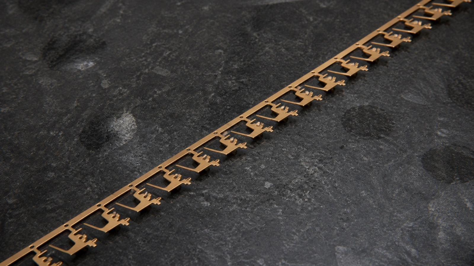
Progressive Die Layout(프로그레시브 금형 스트립 레이아웃)은 부품의 전개 형상을 코일 소재 위에 배열하는 도면을 넘어, 매 스트로크에서 소재·반제품·스크랩의 이동과 지지·성형·분리를 규정하는 생산 기준입니다. 피치와 스트립 폭을 과도하게 줄이면 공구 단면과 캐리어 강성이 부족해지고, 파일럿 유입하중·성형 간섭·하중 편중이 커질 수 있습니다.
안정적인 레이아웃은 기능면, 버 방향, 압연방향, 도금영역과 절곡축을 먼저 고정한 뒤 피치와 캐리어를 결정합니다. 여기에 피더·레벨러·프레스의 운전 범위, 스크랩 배출, 금형 보호 센서와 양산 승인 조건까지 연결되어야 목표 속도에서도 같은 치수와 형상을 반복할 수 있습니다.
설계 입력조건
설계의 출발점은 재료 이용률이 아니라 완성품의 승인 기준입니다. 조립 기준면, 접촉면, 스프링 작동부, 하우징 삽입면과 위치결정 홀을 구분하고, 핵심 품질특성(CTQ)과 버 제한면·도금면·용접면을 같은 설계 입력자료에서 고정합니다. 부품 방향을 회전하면 네스팅 효율은 높아질 수 있지만 압연방향, 버 방향과 선택도금 위치가 달라질 수 있습니다.
완성 형상을 평면으로 전개할 때는 굽힘 중립축뿐 아니라 절곡·성형에 따른 투영 길이 변화와 캐리어 구속 방향을 함께 검토합니다. 성형부가 피치를 당기거나 밀면 파일럿 홀이 정확해도 제품 중심과 절곡 각도가 변합니다. 기능면을 기준으로 전개 방향을 정하고, 성형 변형이 파일럿 기준부로 전달되지 않는 캐리어 구조를 설계해야 합니다.
프레스의 가용 하중, 볼스터 면적, 다이하이트, 스트로크, 허용 편심하중과 피더 가속도도 초기 입력조건입니다. 도면 리비전, 소재 사양, 목표 속도, 윤활 방식과 후공정을 하나의 관리 기준으로 동결해야 트라이아웃 수정이 다른 스테이션의 간섭과 압력 중심을 다시 바꾸는 일을 줄일 수 있습니다.
소재 요구사항
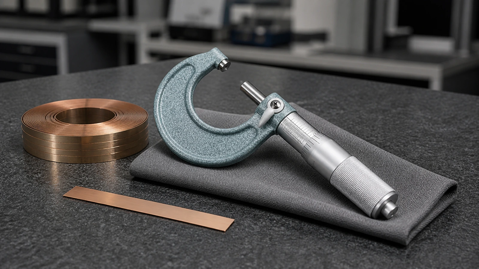
소재 조건을 정의할 때는 합금명과 명목 두께만으로 판단하지 않습니다. 동일 합금이라도 질별(temper)과 열처리·냉간가공 이력에 따라 항복강도, 굽힘성, 최소 굽힘반경과 스프링백이 달라집니다. 전기접점용 인청동과 고성능 동합금은 공급사가 보증하는 강도·경도 범위와 방향별 굽힘성 자료를 우선 확인해야 합니다. 판두께 허용차는 전단 하중, 펀치·다이 클리어런스, 브리지 강성과 성형 높이에 직접 반영됩니다.
코일 폭 공차, 캠버, 코일 세트와 에지 웨이브는 가이드 접촉, 횡방향 이송 안정성과 파일럿 유입하중에 영향을 줍니다. 파일럿이 캠버나 가이드 불량을 상시 보정하도록 설계해서는 안 됩니다. 허용범위의 상한과 하한에서도 캐리어가 비틀리지 않고 이송되어야 하며, 코일 시작·중간·종료 구간의 두께와 폭 추이를 기록하면 소재 로트와 금형 변동을 분리해 판단할 수 있습니다.
압연방향은 전개도에 표시하고 주요 절곡축과의 관계를 고정합니다. 선도금 소재는 도금 띠의 위치와 폭, 소재 상·하면, 절단 후 노출면을 함께 지정합니다. 굽힘 외측의 인장 변형과 공구 마찰이 도금층 균열·박리·긁힘으로 이어지는지는 실제 성형 시편으로 확인해야 합니다.
| 관리 항목 | 도면·발주 기준 | 레이아웃 영향 | 양산 확인 |
|---|---|---|---|
| 합금·질별 | 재질 규격, 질별, 강도·경도 범위 | 절곡 방향, 최소 성형반경, 스프링백 보정 | 재질 성적서, 경도, 로트 편차 |
| 판두께 | 명목 두께와 허용차 | 전단 하중, 클리어런스, 브리지 강성, 성형 높이 | 코일 시작·중간·종료 두께 |
| 코일 폭·캠버 | 폭 허용차, 캠버, 에지 상태 | 스트립 가이드 여유, 횡이동 안정성, 파일럿 유입하중 | 폭 추이, 횡이동, 가이드 마모 |
| 압연방향 | 압연방향 표시, 절곡축 제한 | 부품 배치각도, 굽힘 균열, 스프링 특성 | 절곡 외측 균열, 각도 편차 |
| 표면·도금 | 도금 종류, 띠 위치, 면 방향, 외관 기준 | 네스팅 방향, 성형 위치, 금형 이염 방지 | 도금 균열, 박리, 긁힘, 기재 노출 |
이송 방향·피치·스트립 폭
이송 방향은 네스팅 효율보다 기능면과 성형 방향을 기준으로 결정합니다. 주요 절곡축과 압연방향, 제품에 남는 버, 도금면, 컷오프 흔적과 완성품 배출 방향이 동시에 맞아야 합니다. 좌우 반전이나 180도 회전 배치는 같은 형상처럼 보여도 접촉면과 스프링 작동 방향을 바꿀 수 있습니다.
피치는 한 스트로크당 스트립의 이송량이며 모든 스테이션의 기준 위치를 결정합니다. 전개 길이에 최소 브리지만 더하면 펀치 벽두께, 스크랩 낙하 공간, 파일럿 배치와 성형부 통과 높이가 부족할 수 있습니다. 지나치게 작은 피치는 공구 강성과 배출 안정성을 떨어뜨립니다. 반대로 불필요하게 큰 피치는 소재 사용량과 금형 길이를 늘리고, 긴 금형에서는 열팽창에 따른 누적 피치 편차와 하중 배치 관리가 어려워질 수 있습니다.
스트립 폭과 가이드 기준은 제품 외곽, 캐리어·사이드 웹, 코일 폭 공차와 캠버 여유를 함께 고려해 결정합니다. 교호 배치와 다열 네스팅은 재료 이용률을 높일 수 있지만 절곡 방향, 도금면, 금형 폭과 압력 중심이 허용될 때만 적용합니다. 경제성은 양품 한 개당 소재비, 금형 상각비, 프레스 점유시간과 유지보수비를 합친 총원가로 평가합니다.
| 요소 | 도면 정의 | 결정 기준 | 검증 포인트 |
|---|---|---|---|
| 이송 방향 | 진행 화살표, 소재 상·하면, 압연방향 | 절곡축, 버, 도금면, 배출 방향 | 라인 배치와 실제 코일 방향 일치 |
| 피치 | 1스트로크당 이송량과 스테이션 기준 위치 | 제품 전개, 브리지, 공구 강성, 스크랩 공간 | 목표 속도에서 과송·미송 여부 |
| 스트립 폭 | 기준 에지와 전체 폭 | 제품 폭, 캐리어, 가이드, 캠버 | 횡이동, 에지 파단, 가이드 접촉 |
| 파일럿 기준 | 홀 위치, 작동 스테이션, 기준선 | 기능홀 보호, 보정량, 핀 강성 | 홀 늘어남, 파일럿 흔적, 중심 편차 |
| 캐리어·브리지 | 형식, 폭, 연결 위치, 컷오프 위치 | 스트립 강성, 성형 구속, 재료 이용률 | 비틀림, 늘어남, 절곡 후 피치 변화 |
| 스크랩·배출 | 슬러그·골격·제품의 분리 방향 | 낙하 공간, 슈트, 센서, 유지보수 | 적층, 스크랩 역상승(풀업), 배출 지연 |
캐리어·브리지
캐리어는 최종적으로 제거되는 소재이면서, 파일럿 기준을 유지하고 반제품을 모든 스테이션으로 운반하는 임시 구조체입니다. 피더의 인장·압축력, 절곡 반력, 스트리퍼 누름력과 고속 이송 관성을 견뎌야 합니다. 캐리어가 늘어나거나 비틀리면 파일럿 홀 위치가 맞아도 실제 제품 중심은 달라집니다.
단측 캐리어는 재료 이용률과 공구 접근성이 좋지만 비대칭 제품에서는 횡굽힘과 비틀림이 커질 수 있습니다. 양측 캐리어는 스트립 자세가 안정적인 대신 소재 사용량과 컷오프 공정이 늘어납니다. 중앙 캐리어는 좌우 하중 전달에 유리하지만 제품 내부 형상과 배출 구조에 따라 적용 범위가 제한됩니다.
브리지의 폭·길이·개수·연결 위치는 함께 결정합니다. 좁은 브리지는 노칭과 절곡 반력으로 늘어나거나 찢어지고, 과도하게 넓으면 재료 손실과 컷오프 하중이 증가합니다. 성형으로 투영 길이가 변하는 부품은 유연 캐리어·변형 흡수 슬롯·연결부 순차 절단을 적용해 성형 변형이 파일럿 기준부로 전달되지 않도록 합니다.

파일럿·이송 정밀도
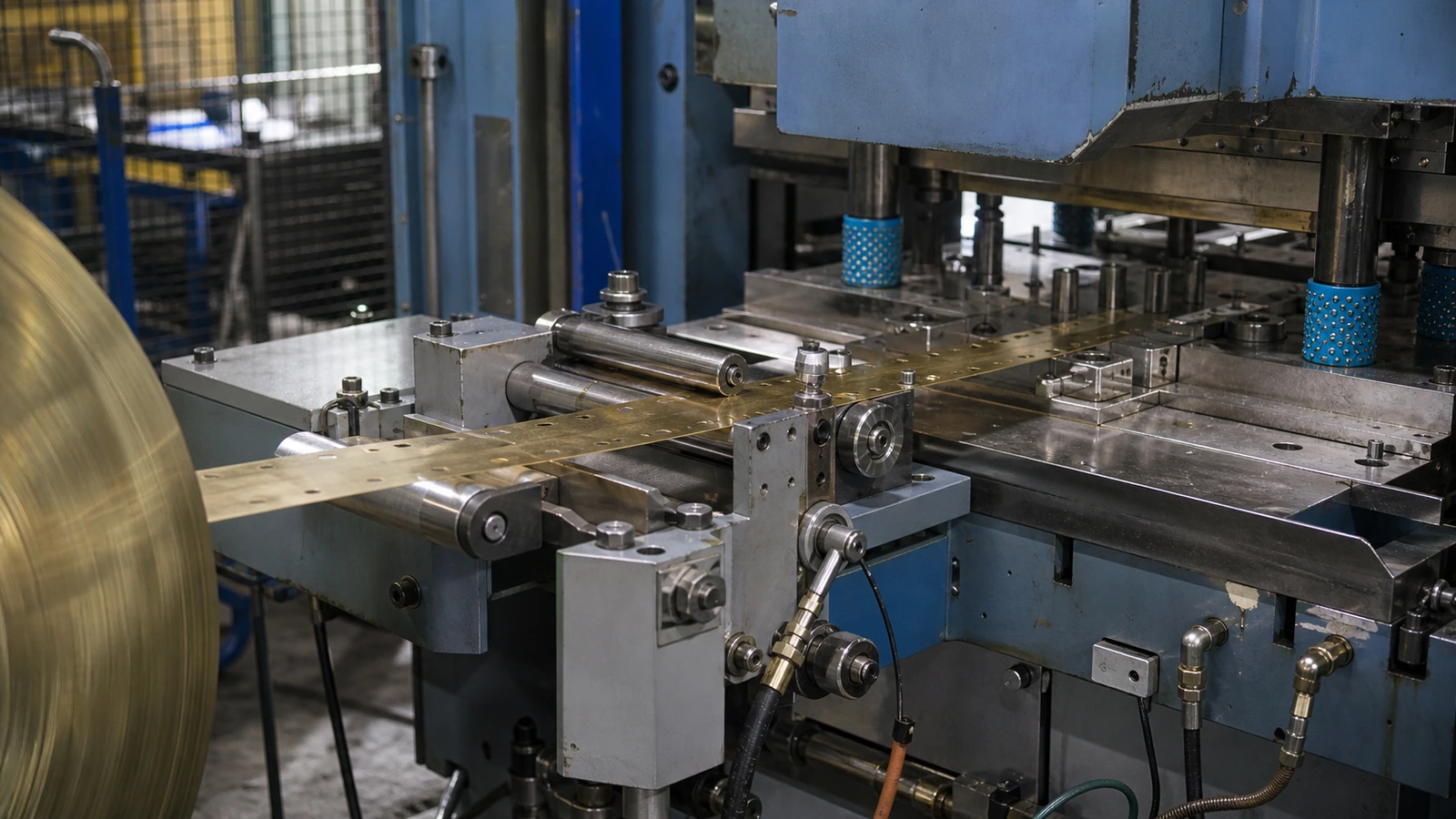
피더는 설정된 피치만큼 스트립을 운반하고, 파일럿은 각 스트로크에 남은 제한된 이송 오차를 최종 보정합니다. 파일럿이 불안정한 피더나 가이드 조건을 대신하면 홀 늘어남, 캐리어 좌굴과 핀 파손이 발생할 수 있습니다. 파일럿 홀은 강성이 충분한 초기 스테이션의 캐리어 영역에 가공하고 다음 스테이션부터 사용합니다. 기능홀 사용이 별도로 검증되지 않았다면 제품 기능홀과 분리된 전용 파일럿 홀을 적용합니다.
파일럿 선단은 잔류 오차를 부드럽게 받아들이고 직선부가 최종 위치를 결정해야 합니다. 스트리퍼가 소재를 평탄하게 지지한 상태에서 진입하며, 피드 릴리스 타이밍은 파일럿 진입과 동기화합니다. 금형이 열릴 때는 파일럿이 완전히 빠지고 리프터가 성형부를 안전한 높이까지 올린 뒤 다음 이송을 시작합니다.
저속에서 정상인 조건도 목표 속도에서는 코일 루프, 피더 가속도, 패스라인과 윤활 상태 때문에 달라질 수 있습니다. 파일럿 홀의 편마모와 늘어남, 캐리어 굽힘, 실제 이송 파형을 목표 속도에서 확인하고 피드 센서 또는 비전 검사 데이터와 함께 관리합니다.
스테이션 분할·공정 순서
스테이션 배열은 각 피처의 가공 순서와 상호 의존성을 결정하는 설계입니다. 일반적인 흐름은 파일럿 홀과 기준 피어싱, 내부 슬롯·노칭, 외곽 윤곽, 엠보싱·랜싱, 예비성형, 최종 절곡, 리스트라이크와 컷오프입니다. 후속 성형으로 변형될 기능홀은 절곡 이후 배치를 검토하되, 피어싱 지지면·스크랩 배출·공구 접근성이 확보되는 경우에만 적용합니다.
외곽을 초기에 지나치게 제거하면 캐리어와 제품 연결부가 약해집니다. 긴 절단 윤곽과 인접 노칭은 여러 스테이션으로 분할해 펀치 강성과 스크랩 배출 공간을 확보합니다. 성형 높이가 큰 피처는 다음 공구와 스트리퍼 아래를 안전하게 통과하도록 단계적으로 올리고, 상형 접근부터 다음 피드까지 전체 동작의 3차원 간섭을 확인합니다.
아이들 스테이션은 공구 벽두께, 성형부 통과 공간, 캠·센서 설치, 스크랩 배출과 후속 수정 여유를 확보하는 설계 요소입니다. 스테이션 수를 무조건 줄이기보다 각 공정을 독립적으로 조정하고 교환형 인서트로 유지보수할 수 있는 구조가 양산 안정성에 유리합니다.
절곡·스프링백
스프링백은 성형된 소재가 공구에서 풀린 뒤 탄성 회복으로 각도와 높이가 변하는 현상입니다. 항복강도, 탄성계수, 판두께, 압연방향, 굽힘반경, 마찰과 잔류응력의 영향을 받으므로 명목 소재 한 조건으로 보정량을 고정하면 로트 변화에 취약합니다.
깊은 절곡과 복합 스프링 형상은 예비굽힘, 중간굽힘과 최종 성형으로 나누는 편이 안정적입니다. 한 스테이션에서 급격하게 굽히면 외측 균열, 도금 손상, 소재 미끄러짐과 캐리어 반력이 커집니다. 최종 각도는 제한적인 오버벤딩, 리스트라이크 또는 사이징으로 조정하되, 과도한 코이닝으로 기재가 얇아지거나 도금층이 손상되지 않도록 관리합니다.
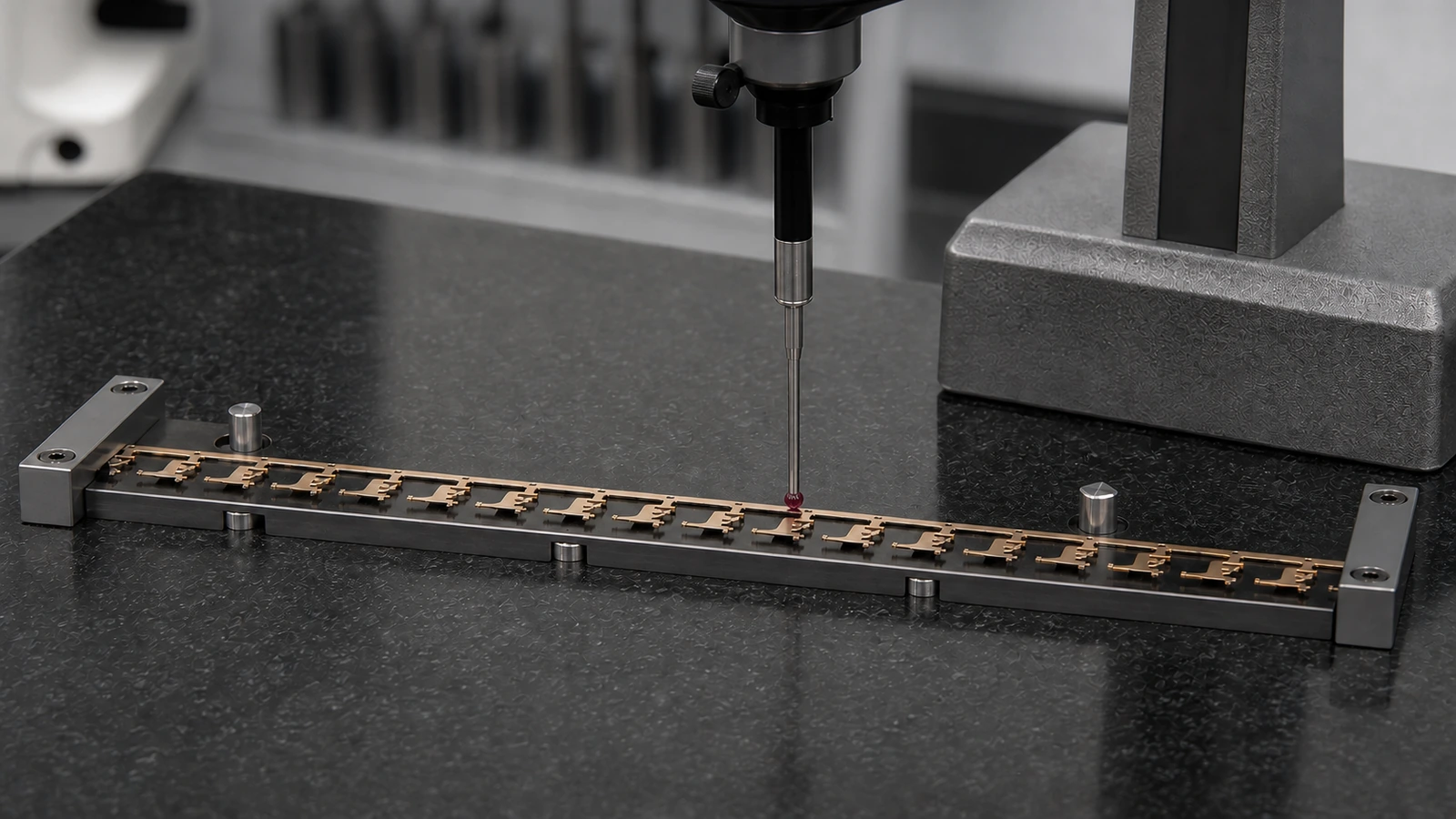
캐리어에 연결된 상태에서 측정한 형상은 컷오프 뒤 자유상태와 다를 수 있습니다. 승인 측정은 최종 분리 후 규정된 자세와 검사 지그에서 수행하며, 시간 의존성이 확인된 부품만 측정 대기시간을 표준화합니다. 각도·성형 높이뿐 아니라 내측 반경, 외측 균열, 접촉 딤플 위치와 스프링 하중 또는 접촉력을 함께 확인합니다.
압력 중심·프레스 선정
금형 하중 검토에는 피어싱과 블랭킹뿐 아니라 절곡, 성형, 스트리핑, 패드와 스프링 하중이 포함됩니다. 각 공정이 최대 하중에 도달하는 슬라이드 위치가 서로 다르므로 정적인 합계만으로 실제 편심하중을 판단할 수 없습니다. 스테이션별 힘과 위치를 기준으로 스트로크 구간별 압력 중심을 검토해야 합니다.
높은 절단 하중이 한쪽에 몰리면 슬라이드가 기울고 펀치·다이 클리어런스가 좌우로 달라질 수 있습니다. 이는 편측 버, 펀치 치핑, 공구 마모와 제품 평탄도 변화로 이어집니다. 절단 하중을 여러 스테이션으로 분산하고 스테이션 배열과 금형 설치 위치를 조정해 압력 중심을 프레스 중심에 가깝게 배치합니다.
프레스는 명판 톤수만으로 선정하지 않습니다. 제조사의 하중–스트로크 곡선에서 실제 가공 위치의 가용 하중과 정격 하중점, 스트로크당 작업에너지, 하사점 반복정밀도, 볼스터·다이하이트, 프레임 강성 및 허용 편심하중을 함께 검토합니다. 양산에서는 정상 하중 파형을 기준화해 펀치 마모, 슬러그 끼임, 소재 두께와 윤활 변화를 조기에 감지합니다.
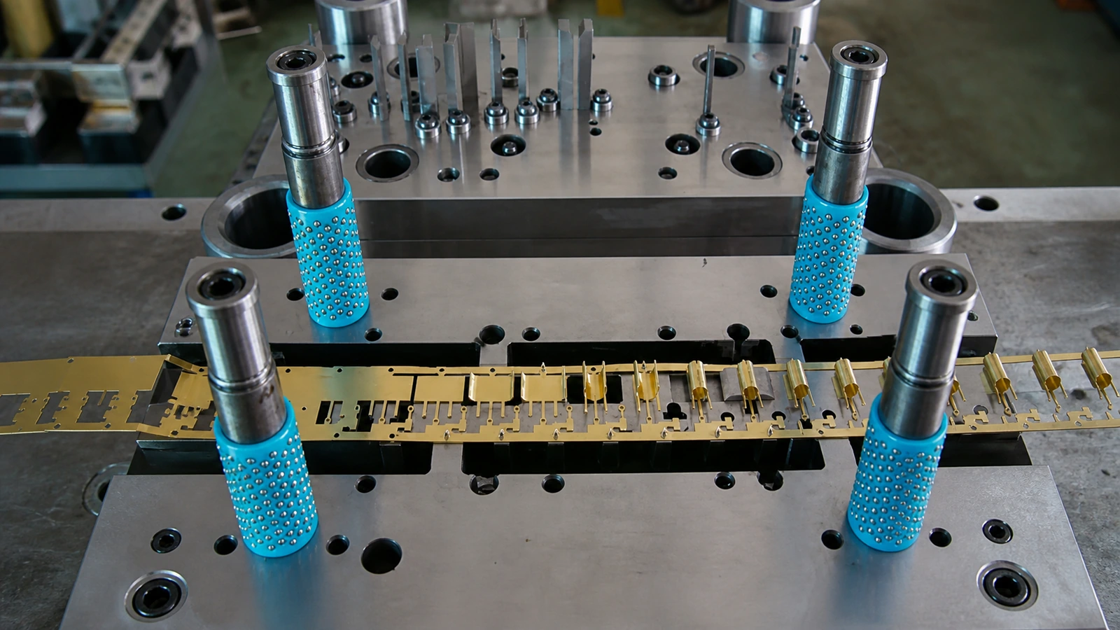
간섭·스크랩·금형 보호
간섭 검토는 금형이 완전히 닫힌 한 위치에 한정하지 않습니다. 상형 접근, 스트리퍼 접촉, 파일럿 진입, 절곡과 리스트라이크, 상형 복귀, 리프터 상승과 다음 피드까지 전체 동작을 확인합니다. 성형된 제품은 평판보다 높은 공간을 차지하고 탄성 회복으로 경로에서 벗어날 수 있으므로 캐리어, 가이드, 센서 브래킷과 체결부도 3차원 검토에 포함합니다.
모든 스크랩은 발생 순간부터 금형 밖으로 나갈 때까지 경로가 정의되어야 합니다. 작은 슬러그는 펀치에 붙어 역상승하거나 다이 내부에 적층될 수 있고, 길고 얇은 골격 스크랩은 슈트에서 말리며 배출을 막을 수 있습니다. 다이 낙하공간과 슈트 각도는 실제 스크랩 형상과 윤활 조건으로 검증하고, 완성품과 캐리어 골격의 배출 경로를 분리합니다.
금형 보호 센서는 미송·과송, 스트립 종료, 좌굴, 파일럿 미진입, 슬러그 역상승, 제품 미배출, 스크랩 적체와 윤활·공압 이상을 공정 위험에 맞춰 감지해야 합니다. 각 센서의 정상 스위칭 구간을 크랭크 각도로 설정하고, 의도적인 단선·미송·제품 미배출 시험으로 다음 손상 스트로크 전에 정지하는지 검증합니다. 센서 우회 권한과 재가동 절차도 제어 계획에 포함합니다.

트라이아웃·양산 승인
트라이아웃은 금형의 단순 작동 여부가 아니라 설계 가정을 실제 소재와 설비에서 검증하는 과정입니다. 저속 단동으로 스크랩 분리와 공구 흔적을 확인한 뒤 연속 운전 속도를 단계적으로 높입니다. 각 단계에서 이송 위치, 파일럿 홀 변형, 스트립 비틀림, 제품 높이와 각도, 버와 하중 파형을 동일한 스트로크 조건으로 기록합니다.
치수 승인은 완성품의 핵심 품질특성만으로 끝내지 않습니다. 파일럿 기준과 제품 중심의 관계, 스테이션별 중간 형상, 캐리어 피치, 폭 방향 이동과 컷오프 전후 변형을 함께 측정해야 원인을 추적할 수 있습니다. 코일 시작·중간·종료 구간과 승인된 강도·두께 범위를 포함한 시편을 사용하고, 금형이 열적으로 안정된 뒤의 결과도 구분해 확인합니다.
양산 승인은 목표 속도 연속운전에서 생산량, 핵심 품질특성의 공정능력, 센서 인터록 응답, 스크랩 배출 안정성과 초기 공구 마모 추세를 확인해 결정합니다. 공정능력 평가는 측정시스템 분석(MSA)이 완료된 조건에서 수행하고, 공구 수명은 별도의 수명검증 계획과 예방보전 기준으로 관리합니다. 소재 공급사, 질별, 판두께, 윤활유, 프레스·피더 조건이나 공구 재질이 변경되면 영향 범위를 평가하고 필요한 항목을 재검증합니다.
English Technical Overview
Progressive Die Strip Layout Design: Feed Pitch, Carrier Geometry, and Material Utilization
A progressive die strip layout is more than a drawing that arranges unfolded part geometry on coil stock. It defines how the material, workpiece, and scrap are transported, supported, formed, and separated during every press stroke. Reducing pitch and strip width solely to improve material utilization can compromise carrier rigidity, pilot correction, forming clearance, and load balance.
A production-ready layout begins with functional surfaces, burr direction, rolling direction, plated zones, and bend axes. Pitch and carrier geometry are established only after these boundaries are fixed. Feeder and press capability, scrap evacuation, die-protection sensors, and production-approval criteria must then be integrated into the same process definition.
DESIGN INPUTS AND CONSTRAINTS
The primary input to a strip layout is the finished-part acceptance criteria, not the desired material yield. Assembly datums, contact surfaces, spring members, housing interfaces, locating holes, and other critical-to-quality features must be identified first. Burr-sensitive surfaces, cosmetic areas, plated zones, and welding interfaces require the same level of definition.
Flattening the final three-dimensional geometry is only the beginning. The layout must account for bend-axis orientation relative to the rolling direction, changes in projected length during forming, and the restraint imposed by the carrier. Rotating a blank can improve nesting while simultaneously reversing the burr direction, moving a selective plating band, or placing a critical bend in an unfavorable orientation.
The production press and peripheral equipment are also design boundaries. Available press capacity through the working portion of the stroke, bolster dimensions, stroke length, shut height, allowable off-center loading, feeder width, acceleration, and straightener capacity can limit the overall die length and number of stations. The target production rate is therefore an initial design input rather than a setting chosen after the die has been completed.
Drawing revision, CTQ characteristics, material specification, target speed, lubrication, and downstream processes should be captured in a common, revision-controlled design-input record. A late change to part geometry or stock properties can alter station clearance, carrier strain, and the center of pressure throughout the die.
STOCK REQUIREMENTS
For strip-layout development, alloy designation and nominal thickness alone are insufficient. Different tempers within the same alloy designation can produce different yield strength, hardness, elongation, bendability, and springback. For spring contacts made from phosphor bronze or high-performance copper alloys, the guaranteed material-property range is more useful than a single nominal value.
Thickness tolerance affects cutting load, punch-to-die clearance, bend radius, bridge stiffness, and finished height. Coil-width tolerance, camber, coil set, and edge wave influence strip guidance and the amount of positional correction demanded from the pilots. The layout must remain stable at the upper and lower limits of the approved material range.
Rolling direction must be marked on the flat-pattern definition and controlled relative to critical bend axes. Bending across the rolling direction is commonly favorable for copper-alloy strip, but the permitted bend radius must always be confirmed for the specific alloy, temper, and thickness. A rotated nesting arrangement is acceptable only after bendability has been verified.
For preplated stock, the plating-band position, width, coated face—including the designated top or bottom surface—and prohibited forming regions must be shown in the progression definition. High tensile strain on the outside of a bend can crack the coating or expose the substrate. Cut edges are normally unplated unless a subsequent finishing operation is specified.
FEED DIRECTION, FEED PITCH, AND STRIP WIDTH
Feed direction is established from functional and forming requirements rather than nesting efficiency alone. Rolling direction, bend axes, burr orientation, plated surface, cutoff witness, product discharge, and scrap flow must remain compatible. Mirrored or 180-degree rotated blanks may appear geometrically identical while producing different functional surfaces and forming behavior.
The physical line arrangement must also be considered. The uncoiler, straightener, feeder, press, part discharge, and scrap system should form a practical material path with adequate access for die setting, inspection, and sensor maintenance.
Feed pitch is the programmed strip advance per press stroke and fixes the centerline of every station. It should not be defined simply as the unfolded part length plus a minimum bridge. Tool-section strength, projecting formed features, pilot placement, scrap drop openings, and feeder setup all require space within the progression.
An excessively short pitch can weaken adjacent punches and die sections, trap slugs, or create interference between formed features and the next station. An unnecessarily long pitch increases stock consumption, die length, thermal sensitivity, and the difficulty of controlling off-center loading. The correct value is the shortest pitch that remains robust at production speed.
Strip width includes the blank envelope, carrier system, edge webs, guide engagement, stock-width tolerance, and camber allowance. A narrower strip can improve nominal material utilization but may increase edge tearing, guide disengagement, and carrier twist. Alternate nesting and multiple-row layouts are suitable only when bend direction, plating side, burr direction, die width, load center, and inspection access remain acceptable. The correct economic measure is total cost per approved part.
CARRIER AND BRIDGE DESIGN
The carrier is more than scrap reserved for the end of the process. It is a temporary structural member that preserves the pilot datum and transports the workpiece through every station. It must withstand feeder tension and compression, forming reactions, stripper force, and high-speed inertia. Once the carrier deforms, an accurate pilot hole no longer guarantees accurate part position.
A single-sided carrier can improve material utilization and tool accessibility, but it is more susceptible to lateral bending and torsion on asymmetrical parts. A double-sided carrier generally provides greater strip stability at the cost of additional material and cutoff operations. A center carrier can distribute load effectively but is limited by part geometry and discharge requirements.
Bridge width, length, quantity, and attachment position must be evaluated together. A narrow bridge may stretch or tear during notching and forming. An unnecessarily wide bridge increases material loss and cutoff load. Generous transition radii at the carrier-to-bridge junction reduce local fatigue concentration.
When forming changes the projected length of a part, a fixed-pitch carrier can pull the workpiece out of shape. Flexible carrier sections, strain-relief slots, or staged release of selected attachments may be required. The pilot datum must remain rigid while the forming region is allowed to absorb the necessary length change. Attachment points should avoid contact surfaces, active spring areas, and assembly datums.
PILOTING AND FEED ACCURACY
The feeder advances the strip by the programmed progression, while the pilots correct the residual positional error during each stroke. Pilots must not compensate for an unstable feed system. Excessive correction can elongate pilot holes, buckle the carrier, or break the pilot.
Pilot holes are typically pierced in an early, well-supported station and used for location from the following station onward. Using a finished functional hole as the pilot reference can introduce scratches or deformation into a controlled feature. Precision stampings therefore benefit from dedicated pilot holes in the carrier.
The pilot lead should capture the remaining feed error smoothly, while the straight locating section establishes the final position. The stripper must hold the strip flat as the pilot enters. Long or slender pilots require adequate stripper guidance and sufficient strength for the approved correction range and production speed.
Feeder release must be synchronized with pilot entry. A late release forces the pilot to work against the feeder, while an excessively early release can allow uncontrolled strip movement. Before the next feed, the pilots must be fully withdrawn and the lifters must raise formed features above all lower tooling and guides. Repeatability must be verified at target speed because coil-loop behavior, lubrication, and the feed signature may differ from slow-speed conditions.
STATION SEQUENCE
Station planning defines the manufacturing order and dependencies of every feature. A common sequence includes pilot and datum piercing, internal slots and notches, progressive contour development, embossing or lancing, preforming, final bending, restrike, and cutoff. If a functional hole would be distorted by a later forming operation, it may need to be produced after forming.
Removing too much perimeter material early can weaken the strip and the workpiece attachments. Long cutting contours and closely spaced notches should be distributed across stations to preserve punch strength and carrier rigidity. Concentrating thin tool sections and fragile scrap in a single station increases the risk of chipping, slug jamming, and uneven burr formation.
Embosses and lanced spring features should be produced while the surrounding material remains adequately supported. Tall features require staged forming and sufficient pass clearance below the stripper and between subsequent tools. The formed geometry must travel through the next feed motion without contacting the die, guides, or lifters.
An idle station is a functional design element. It can provide tool-section strength, carrier recovery, cam or sensor space, formed-feature clearance, scrap evacuation, and improved load distribution. Final cutoff follows the critical forming and inspection operations, and the finished part and carrier skeleton must leave through distinct, verified paths.
BENDING AND SPRINGBACK CONTROL
Springback is the elastic shape recovery that occurs after the formed material is released from the tooling. It is influenced by yield strength, elastic modulus, thickness, rolling direction, bend radius, friction, and residual stress. A compensation value based only on nominal material data may therefore be unstable across production lots.
Deep bends and complex spring-contact forms are more robust when divided into pre-bend, intermediate bend, and final sizing stages. A severe bend performed in one station increases outer-surface cracking, plating damage, sliding, and reaction force on the carrier. Staged forming distributes strain and provides better control of tool clearance.
Final geometry can be corrected by controlled overbend, restrike, sizing, or limited coining. Excessive coining sharply increases load and can cause excessive substrate thinning or damage the coating. Replaceable forming inserts and adjustable support elements provide a controlled method for tryout correction and future maintenance.
Geometry measured while the workpiece is attached to the carrier may not represent the free finished part. Approval measurements should be performed after final separation in the specified inspection orientation. A stabilization period should be standardized only for parts with verified time-dependent behavior. Inspection should include bend angle, height, inner radius, outer-surface cracking, coating integrity, contact-dimple position, and spring force after the die reaches its normal production temperature.
CENTER OF PRESSURE AND PRESS SELECTION
Total die load includes piercing, blanking, forming, bending, stripping, pads, and springs. Cutting operations often create the largest instantaneous force, but different operations reach their peak at different slide positions. A static force total alone does not describe the actual off-center load through the stroke.
The center of pressure must be evaluated from station force and position. Concentrating high cutting forces on one side can tip the slide and change punch-to-die clearance across the die. The result may be one-sided burr growth, accelerated punch wear, chipping, and loss of part flatness.
Splitting cutting operations, changing the station sequence, or introducing an idle station can reduce load concentration. The die can also be positioned on the bolster to bring the pressure center closer to the press center, provided that clamping, feeder alignment, and discharge paths remain valid.
Press selection requires more than comparing rated tonnage. Available force at the actual working position, energy per stroke, production speed, bottom-dead-center repeatability, bolster size, shut height, frame rigidity, allowable off-center load, concentrated-load limits, and capacity at each suspension point must be considered. At high speed, inertia, vibration, feed synchronization, and thermal growth are equally important.
A load monitor should establish normal total and left-right waveforms after the process is stable. Monitoring the entire working signature rather than only the peak load can reveal punch wear, trapped scrap, stock-thickness variation, lubrication changes, and load imbalance before they create defects or tooling damage.
INTERFERENCE, SCRAP HANDLING, AND DIE PROTECTION
Interference analysis must cover the complete motion cycle rather than only the fully closed die position. The review includes upper-die approach, stripper contact, pilot entry, forming, restrike, opening, lifter rise, and the next feed movement. A formed workpiece occupies more vertical and lateral space than incoming flat strip, and elastic recovery can move it outside its nominal trajectory.
Every slug, offcut, and carrier-skeleton segment requires a defined path from creation to exit. Small slugs are vulnerable to slug pulling, stacking in die openings, and adhesion caused by lubricant. Long, narrow scrap can curl or bridge across a chute and block subsequent pieces. Die openings, chute angles, and exits must be sized for actual scrap geometry and lubrication. Air blow may assist evacuation but should not compensate for an unstable scrap path.
A die-protection sensor must stop the press before the next damaging stroke. Risks include short feed, overfeed, stock end, strip buckle, incomplete pilot entry, incomplete stripper return, slug pull-up, part-out failure, scrap backup, lubrication or air-pressure loss, cam return failure, and abnormal load.
Events expected during every stroke and events that occur only at defined intervals require different monitoring logic. Each sensor must switch within a verified crank-angle window, and deliberate fault tests should confirm that the press stops before damage occurs. Detection logic, stop timing, reset responsibility, bypass authorization, and fault history belong in the control plan and must be validated under actual lubrication and target-speed conditions.
TRYOUT AND PRODUCTION APPROVAL
Tryout begins with progression samples from every station. Comparing pilot piercing, internal cutting, contour development, forming, bending, and cutoff samples identifies the exact operation where distortion first occurs. Single-stroke checks confirm stripper contact, pilot entry and withdrawal, lift height, scrap drop, carrier stability, and part discharge. Pilot witness, hole elongation, bridge whitening, cracking, and carrier twist indicate structural or timing problems that should not be hidden by feed-offset adjustment.
Producing acceptable parts at low speed is not sufficient for approval. The actual production-intent coil stock, straightener, feeder, press motion, passline, and lubrication system must be used while speed is increased progressively to the production target. Feed variation, loop behavior, die temperature, load signature, sensor timing, and scrap flow should be recorded together.
Parts produced after thermal stabilization may differ from first-off samples. Stable-run parts, end-of-coil parts, and restart parts should be compared to establish the true production range. Run-at-rate verification must also confirm sustainable output, unplanned-stop losses, scrap evacuation, sensor response, and tool-temperature behavior.
Approval includes drawing dimensions, burr height and direction, bend angle, cracks, plating damage, flatness, spring force, assembly behavior, and electrical performance according to product requirements. Process capability must be evaluated with a qualified measurement system and separately traceable beginning-, middle-, and end-of-coil samples, plus samples from each lane and cavity.
The approval package should link dimensional and functional results with material records, the process flow, PFMEA, control plan, setup conditions, sensor-interlock tests, baseline load waveforms, master samples, preventive-maintenance requirements, and critical spare parts.
Changes in material source, alloy, temper, thickness, slit width, coating, lubricant, press, feeder, production speed, punch condition, or forming insert require an impact review. The approved strip layout becomes the controlled production standard linking material inputs, die settings, sensor limits, load signatures, and inspection controls. This framework allows material utilization and output to be optimized without compromising tool life or part quality.
추가 정보
검색엔진용 요약
Progressive Die Layout은 피치와 스트립 폭만 정하는 도면이 아니라 캐리어, 파일럿, 공정 순서, 하중 중심과 스크랩 흐름을 통합하는 양산 기준입니다. 소재 방향과 기능면을 고정하고 목표 속도에서 치수, 센서, 하중 파형과 배출 안정성을 함께 검증해야 합니다.
핵심 포인트
- 소재 이용률보다 기능면, 버 방향, 도금영역과 압연방향을 먼저 고정합니다.
- 피치는 제품 길이뿐 아니라 브리지, 공구 강성, 성형 간섭과 스크랩 공간으로 결정합니다.
- 캐리어는 파일럿 기준과 제품 형상을 유지하는 공정 구조체입니다.
- 피더는 이송을 담당하고 파일럿은 남은 위치 오차만 보정해야 합니다.
- 하중 중심과 스크랩 흐름은 실제 소재와 목표 생산속도에서 검증합니다.
- 최종 승인은 자유상태 치수, 기능, 센서 인터록과 하중 파형까지 포함합니다.
FAQ
피치를 가장 작게 설계하면 재료 이용률이 항상 좋아집니까?
명목 이용률은 높아질 수 있지만 공구 벽두께, 브리지 강성, 스크랩 배출과 성형 간섭이 불리해질 수 있습니다. 양품 한 개당 총비용과 금형 안정성을 함께 비교해야 합니다.
단측 캐리어와 양측 캐리어는 어떻게 선택합니까?
제품의 비대칭 정도, 성형 반력, 스트립 폭과 목표 속도를 기준으로 선택합니다. 단측 캐리어는 소재 절감과 접근성에 유리하고 양측 캐리어는 비틀림과 횡이동 제어에 유리합니다.
파일럿이 있으면 피더 정밀도는 중요하지 않습니까?
파일럿은 작은 잔류 오차를 보정하는 장치입니다. 피더 오차가 크면 파일럿 홀과 캐리어가 변형되므로 피더 반복정밀도와 릴리스 타이밍이 먼저 안정되어야 합니다.
교호 네스팅이 가장 경제적인 배치입니까?
절곡축, 버 방향과 도금면이 허용될 때만 경제적입니다. 금형 폭, 스테이션 수, 하중 편심과 검사 복잡도가 커지면 소재 절감보다 전체비용이 증가할 수 있습니다.
스프링백은 금형 각도만 수정하면 해결됩니까?
소재 강도와 두께, 압연방향, 마찰, 캐리어 구속과 금형 온도도 영향을 줍니다. 단계 성형과 리스트라이크를 적용하고 최종 컷오프 후 자유상태에서 검증해야 합니다.
양산 승인은 어느 시점에 완료합니까?
실제 소재와 윤활 조건으로 목표 속도에 도달하고 열적 안정상태에서 치수, 버, 성형 품질, 기능, 하중 파형, 센서와 스크랩 배출이 모두 확인된 뒤 완료합니다.
관련 주제
버 방향과 기능면 설계
접촉면, 조립 기준면과 외관면을 기준으로 버 방향과 컷오프 흔적을 지정하면 후속 조립과 표면 품질의 변동을 줄일 수 있습니다.
고속 프레스 하중 파형
총 톤수뿐 아니라 스트로크 구간별 하중과 좌우 파형을 기준화하면 펀치 마모, 슬러그 끼임과 편심하중을 조기에 감지할 수 있습니다.
인청동 스프링 접점의 절곡
압연방향, 질별, 굽힘반경과 도금 상태를 함께 관리하고 컷오프 후 자유상태에서 스프링백과 기능력을 확인해야 합니다.
내부 링크
관련 키워드
Progressive Die Layout, 프로그레시브 금형, 스트립 레이아웃, 정밀 프레스, 프레스 금형 설계, 스트립 피치, 캐리어 설계, 브리지 강성, 파일럿 핀, 재료 이용률, 인청동 프레스, 스프링백, 하중 중심, 금형 보호 센서