
인청동·베릴륨동·황동 차이:
판접점과 스프링 단자의 소재 선택
인청동·베릴륨동·황동은 모두 전기를 전달하는 동합금이지만, 판접점과 스프링 단자에서 맡을 수 있는 역할은 같지 않습니다. 전도도가 높은 재료가 접촉력을 오래 유지하는 것은 아니며, 인장강도가 높은 재료가 같은 변위에서 더 큰 힘을 내는 것도 아닙니다. 소재 선택의 기준은 조립 직후의 성능을 넘어, 온도·시간·반복 사용을 거친 뒤에도 남는 접촉력과 안정적인 전기 저항입니다.
황동은 성형성과 경제성, 인청동은 강도와 가공성의 균형, 고강도 베릴륨동은 제한된 공간에서의 탄성 변형 여유가 주요 검토점입니다. 이 차이를 합금 등급·조질·부품 형상·제조 이력과 함께 비교해야 불필요한 고급재 사용과 장기 접촉 불량을 동시에 줄일 수 있습니다.
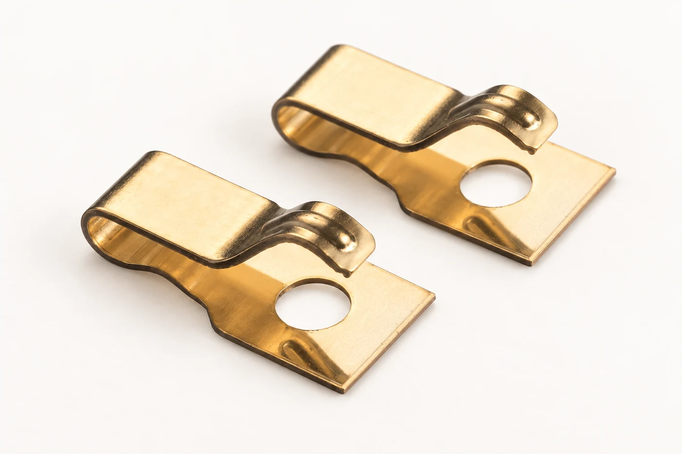
판접점·스프링 단자의 기능 구분
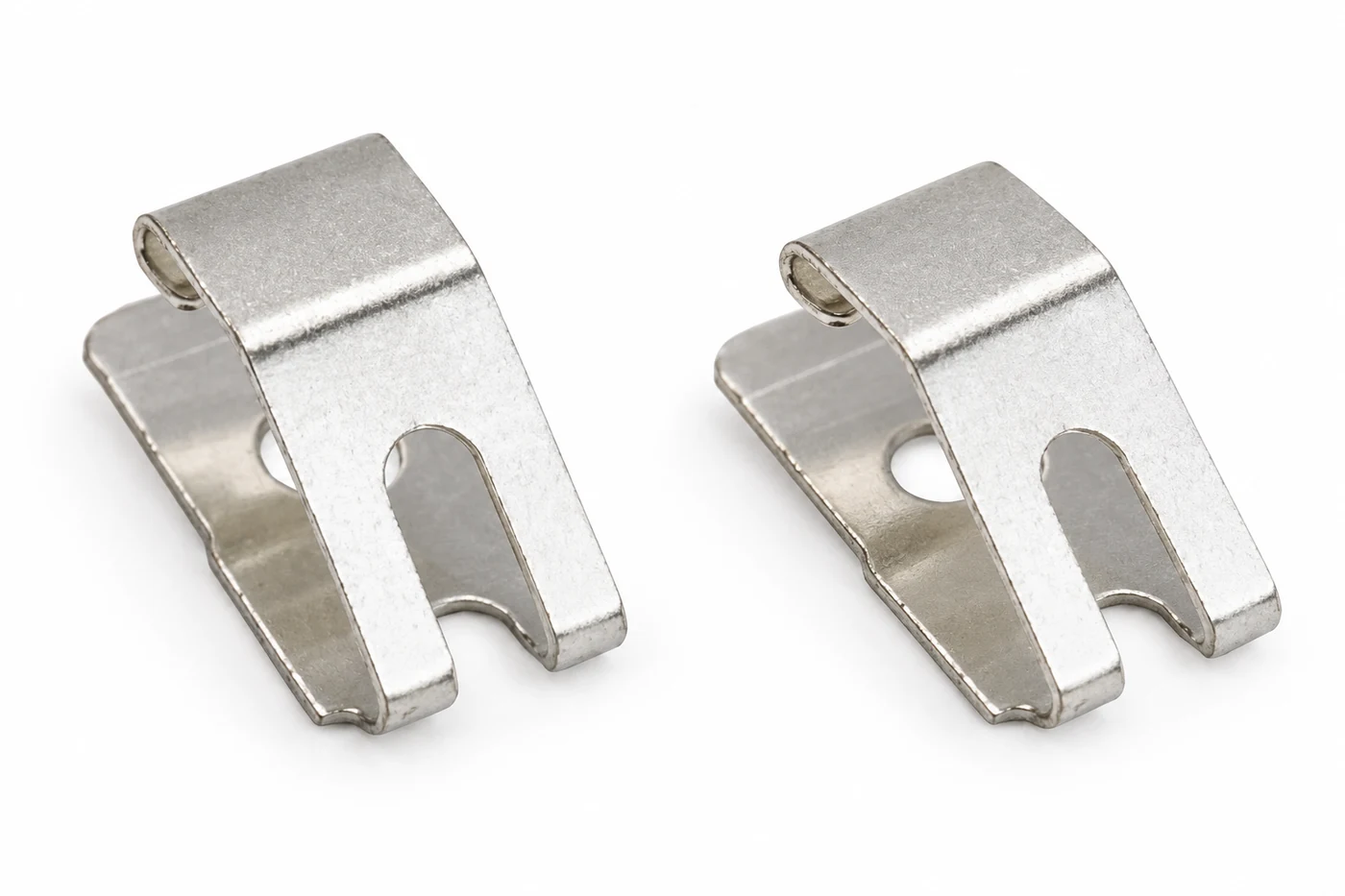
단자의 전류 경로와 탄성 부위를 먼저 구분해야 합니다. 수형 탭처럼 상대 단자에 끼워지는 부품은 일정한 두께와 치수 안정성이 중요합니다. 반면 암형 접촉편, 배터리 판스프링, 기판 접지 핑거는 조립 공차를 흡수하면서 상대 면을 계속 눌러야 합니다. 두 부품이 같은 회로에 있어도 요구되는 재질과 조질은 달라질 수 있습니다.
판접점은 판 형태의 접촉 부품을 넓게 부르는 명칭입니다. 전류를 개폐하며 아크를 받는 은계 접점 팁과, 그 팁을 지지하거나 접촉력을 만드는 동합금 판스프링은 별개입니다. AgNi·AgSnO₂ 등의 개폐 성능을 C5210이나 C17200의 탄성 특성으로 대체해서 판단해서는 안 됩니다.
상용 제품에서도 주석도금 황동 수형 PCB 탭, 인청동 SMT 접촉자, 베릴륨동 다방향 접지 접촉자가 각각 사용됩니다. 이는 적용 가능한 기능의 사례이지 특정 합금의 정격 전류를 정하는 근거는 아닙니다. 전류 정격은 단면·접촉 구조·방열·도금·하우징과 시험 조건이 결합된 완성 부품의 특성입니다.
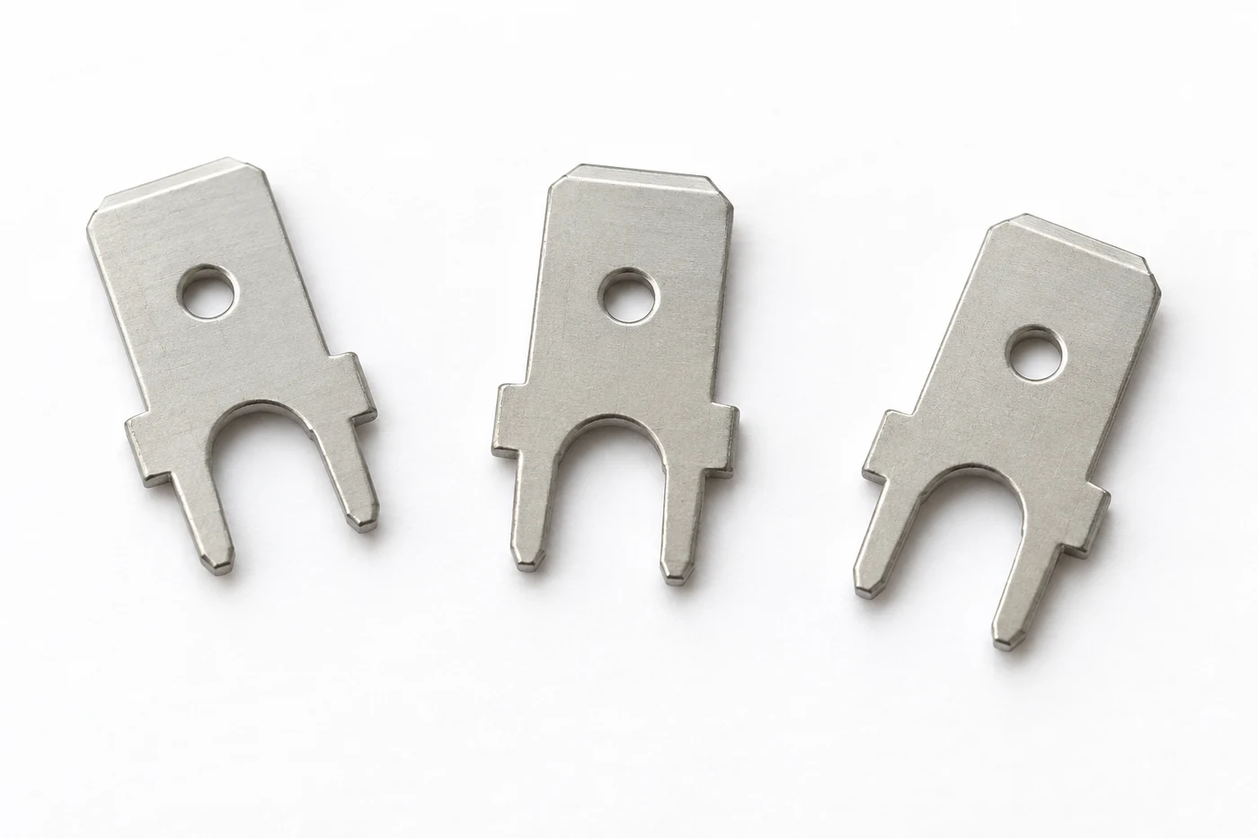
인청동·베릴륨동·황동의 합금 등급
황동은 구리와 아연, 인청동은 구리·주석·인, 베릴륨동은 구리와 베릴륨을 중심으로 구성됩니다. 그러나 재료명만으로 구매하면 성분뿐 아니라 공급 상태도 달라질 수 있습니다. 인청동 C5191과 C5210, 고강도 베릴륨동 C17200을 구분하고, 판·대재에 적용하는 규격과 조질까지 주문서에 연결해야 합니다.
| 재료군 | 비교 대상 | 소재 검토의 중심 |
|---|---|---|
| 황동 | C2600 / C26000 계열 | 성형성·전도도·경제성, 필요한 장기 접촉력 |
| 인청동 | C5191, C5210 | 주석 함량과 냉간가공 상태에 따른 강도·굽힘성 |
| 고강도 베릴륨동 | C17200 / CuBe2 | 시효 전후 상태, 탄성 사용 범위, 성형·열처리 경로 |
| 고전도 베릴륨동 | C17500·C17510 등 | C17200과 다른 강도·전도도 조합, 별도 데이터 검토 |
JIS와 UNS의 대응 명칭은 후보 재료를 찾는 출발점입니다. 성분 범위, 제품 형태, 허용 공차와 시험 방향이 같은지 확인하지 않고 상호 대체를 승인해서는 안 됩니다. C2600의 70/30 황동 계열을 모든 황동의 대표값으로 쓰거나, 고전도 베릴륨동의 전도도를 고강도 C17200에 그대로 적용하는 비교도 피해야 합니다.
색상은 합금 판별 기준이 아닙니다. 금도금 인청동도 금빛이며, 주석도금 황동은 은색으로 보입니다. 성적서의 용해·제조 로트와 입고 라벨을 연결하고, 필요하면 적합한 성분 분석으로 확인해야 합니다. 특히 일반적인 휴대형 XRF만으로 베릴륨 함량까지 확인했다고 판단해서는 안 됩니다.
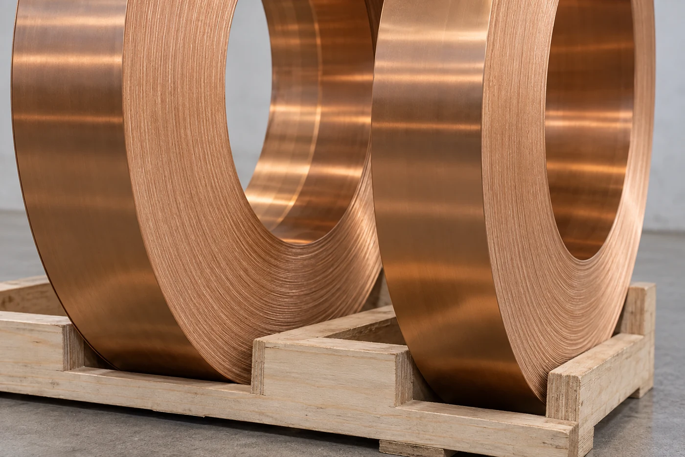
전도도·내력·탄성계수 비교
전도도는 재료 내부에서 전류가 흐르기 쉬운 정도, 0.2% 내력은 인장시험에서 정해진 잔류 변형 기준에 대응하는 응력, 탄성계수는 탄성 구간의 변형에 대한 저항을 나타냅니다. 세 수치는 서로 다른 질문에 답합니다. 특히 0.2% 내력은 영구 변형이 전혀 없는 한계값이 아니므로 미세 접촉자의 허용 응력으로 그대로 사용하지 않습니다.
| 판·대재 예시 상태 | 전도도 (% IACS) | 0.2% 내력 (MPa) | 탄성계수 (GPa) |
|---|---|---|---|
| C2600-H | 28 | 260–430 | 110 |
| C5191-H | 13 | 520 이상 | 105 |
| C5210-H | 13 | 510–625 | 110 |
| C17200-½H / TD02, 시효 전 | 15–19 | 530–660 | 125 |
| C17200-½HT / TH02, 시효 후 | 22–28 | 1,100–1,350 | 131 |
위 값은 공개된 공급사 판·대재 자료의 비교 예시이며, 서로 다른 조질의 특성을 보여줍니다. 규격의 공통 보증값이나 동일 강도 조건의 순위표는 아닙니다. 실제 발주에서는 두께 범위·시험 방향·시험편 조건과 해당 공급사의 보증 범위를 다시 맞춰야 합니다.
같은 길이와 단면의 재료라면 13% IACS와 28% IACS의 차이는 벌크 저항에서 약 2.15배의 차이에 해당합니다. 그러나 완성 단자의 전체 저항이 반드시 2.15배가 되는 것은 아닙니다. 접촉 계면, 접합부와 전류가 좁아지는 구간의 저항이 함께 작용하기 때문입니다.
접촉력과 탄성 변형 여유
같은 형상의 판스프링에서 더 높은 강도는 주로 영구 변형을 억제할 수 있는 응력 여유로 작용합니다. 스프링의 초기 강성은 탄성계수와 형상에 좌우됩니다. 따라서 인청동을 베릴륨동으로 바꿨다는 이유만으로 접촉력이 두 배가 된다고 예상해서는 안 됩니다. 재료의 강도 상승을 긴 작동 변위, 작은 설치 공간 또는 얇은 단면으로 활용할 수 있는지 검토하는 편이 정확합니다.
직선형 직사각 단면의 외팔보를 작은 변형 범위에서 비교하면, 두께는 강성에 세제곱으로 영향을 줍니다. 다른 조건이 같을 때 두께가 5% 증가하면 강성은 약 15.8% 커지고, 유효 길이가 5% 길어지면 약 13.6% 작아집니다. 이 계산은 형상 민감도를 보여주는 예시이며, 복잡한 C형·다중 절곡 접촉자에 그대로 적용하는 설계식은 아닙니다.
조립 공차의 양 끝을 모두 검토해야 합니다. 최소 눌림량에서는 전기적으로 필요한 접촉력을 확보하고, 최대 눌림량에서는 영구 변형·과도한 삽입력·기판 또는 하우징 손상을 피해야 합니다. 공차가 큰 구조에서는 강한 재료로 바꾸는 것보다 유효 스프링 길이, 스토퍼 위치와 조립 기준면을 먼저 수정하는 편이 효과적일 수 있습니다.
개발 단계에서는 힘–변위 곡선을 가압과 복귀 방향에서 모두 기록합니다. 자유 높이만 같은 부품도 곡선의 기울기와 복귀 후 잔류 변형은 다를 수 있습니다. 반복 시험의 기준점, 눌림 속도, 접촉 위치와 예비 작동 횟수를 고정해야 소재와 공정의 차이가 비교됩니다.
사용 온도·시간과 장기 접촉력
응력완화는 일정하게 눌린 스프링의 힘이 시간이 지나며 감소하는 현상입니다. 일정 하중에서 변형이 증가하는 크리프, 반복 하중에 의한 피로, 첫 조립에서 생기는 영구 변형과 구별해야 합니다. 초기 접촉력이 충분해도 열과 시간이 겹치면 접촉 저항과 발열의 여유가 줄어들 수 있습니다.
총 힘 손실에는 첫 변형 과정의 자리잡음과 열에 의한 장기 변화가 함께 포함될 수 있습니다. 공개된 동합금 응력완화 연구에서도 이 둘을 분리하여 비교합니다. 예비 삽입 전·후를 서로 다른 초기 상태로 삼으면 같은 재료의 유지율도 다르게 보일 수 있으므로, 시험 시작점을 명시해야 합니다.
냉간가공 황동과 인청동은 조질과 온도 이력에 따라 힘 유지 특성이 달라집니다. 석출강화 베릴륨동은 장기 안정성이 중요한 후보이지만, 소재명만으로 특정 온도에서의 수명을 보증할 수는 없습니다. 주변 온도뿐 아니라 통전 중 단자 자체의 온도, 유지 시간, 변형량과 성형 이력을 함께 비교해야 합니다.
예를 들어 초기 힘 1.0 N인 단자가 내구 조건 후 0.65 N을 유지하고 기능상 최소 힘이 0.60 N이라면, 남는 여유는 0.05 N입니다. 이 값은 설명용 가정이며 재료 성능값이 아닙니다. 평균 유지율만 통과하더라도 로트 편차·공차·측정 불확도가 이 여유를 넘으면 설계는 안정적이지 않습니다. 유지율과 최종 절대 힘을 함께 승인 기준으로 삼아야 합니다.
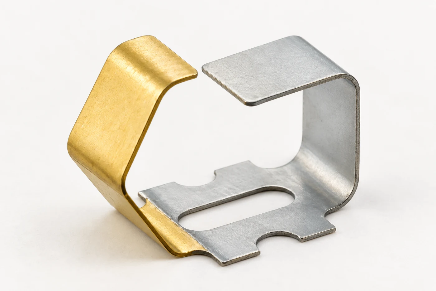
논문·소재 시험과 실제 부품의 연결
C5210-H 냉간압연 판재를 대상으로 한 연구에서는 실온 인장시험과 24시간 응력완화 시험을 결합하여, 변형 속도의 영향을 분리한 강도 성분을 평가했습니다. 해당 조건에서 준정적 0.2% 내력의 약 90%가 비열적 응력 성분으로 추정되었습니다. 이를 고온에서 수년 사용한 접촉자가 90%의 접촉력을 유지한다는 의미로 해석해서는 안 됩니다.
이 결과의 설계상 의미는 시험 속도와 하중 유지 시간이 다르면 같은 소재의 강도 해석도 달라진다는 점입니다. 반면 실제 단자에는 불균일한 굽힘 응력, 국부 성형, 도금·리플로 이력, 상대 부품과의 마찰이 추가됩니다. 소재 시험은 후보를 좁히는 근거로 사용하고, 최종 형상에서는 필요한 기능을 다시 검증해야 합니다.
가속 열시험도 온도만 올려 시간을 단순 환산하면 충분하지 않습니다. 평가 구간에서 지배적인 열화 기구가 유지되는지, 다른 연화·도금 반응·하우징 변형이 개입하는지 확인해야 합니다. 적용 가능한 온도–시간 환산과 장기 외삽 범위는 해당 합금·조질·공정에 근거한 데이터로 한정합니다.
해석과 실험을 연결할 때에는 소재 성적서의 인장 방향, 부품의 압연 방향, 실제 스프링 작동 방향을 나란히 기록하는 것이 유용합니다. 재료 곡선을 교체했는데도 시험과 해석이 맞지 않는다면, 재질 오류만 찾지 말고 구속 조건·접촉 위치·초기 형상과 잔류 응력을 함께 점검해야 합니다.
압연 방향·절곡 반경·스프링백
강도를 높이기 위해 경질 조질을 선택하면 성형 여유가 줄어드는 경우가 많습니다. 인장 연신율이 충분하다는 이유만으로 작은 절곡 반경을 승인해서도 안 됩니다. 굽힘은 외측 표면에 변형이 집중되므로 판 두께, 압연 방향, 버와 가장자리 흠집, 금형 반경의 영향을 크게 받습니다.
최소 굽힘 반경은 내측 반경 R과 판 두께 t의 비율로 비교하되, 굽힘 각도와 시험 방향을 함께 표시합니다. 공급 자료의 Good way·Bad way는 정의 그림과 대조해야 합니다. 통상 절곡 축이 압연 방향에 수직인 경우를 유리한 방향으로 분류하지만, 방향 이름만 주문서에 쓰지 말고 도면에 절곡 축과 압연 화살표를 직접 표시하는 편이 명확합니다.
동일한 C5210도 H·EH·SH 상태와 90°·180° 굽힘에서 허용 범위가 달라집니다. 자료에 R/t=0이 표기되어 있더라도 실제 금형에 반경이 필요 없거나 모든 두께에서 접어도 된다는 뜻은 아닙니다. 시험편 두께·폭과 판정 조건이 한정된 시험 결과로 취급해야 합니다.
프레스 공정에서는 스프링백을 각도 보정만으로 처리하지 않습니다. 코일의 두께·내력 변동, 금형 마모, 윤활량과 성형 순서를 관리하고, 자유 높이와 작동 힘을 함께 측정합니다. 인청동의 인장·압축 비대칭과 하중 반전 효과를 다룬 연구도 단순 인장 곡선만으로 굽힘을 재현하기 어려울 수 있음을 보여줍니다. 복잡한 다단 절곡에서는 실제 시편과 하중–변위 시험으로 보정해야 합니다.
소재 입고부터 프레스·열처리까지
인청동과 황동은 요구 강도를 가진 압연 조질로 공급받아 프레스 성형하는 경로가 일반적입니다. 베릴륨동은 성형 후 시효경화하는 경로와 소재 제조 단계에서 강도를 부여한 밀하든재를 사용하는 경로를 구분해야 합니다. 같은 C17200이라는 표기만으로 공정 순서를 통일할 수 없습니다.
| 공정 | 관리 항목 | 후속 기능에 미치는 영향 |
|---|---|---|
| 입고·슬리팅 | 재질·조질·두께·캠버·압연 방향·로트 | 급송 안정성, 강성·절곡 편차 |
| 전개·타발 | 스프링 뿌리부 형상, 잔여 연결부, 버 방향 | 응력 집중, 도금 손상, 피로 시작점 |
| 단계 성형 | 내측 반경, 과성형량, 지지와 작동 간극 | 자유 높이, 접촉 위치, 영구 변형 |
| 조건부 열처리 | 공급 상태, 실제 부품 온도·시간, 지그와 분위기 | 강도·전도도, 산화, 치수 이동 |
| 세정·도금·포장 | 잔류물, 선택도금 위치, 휨·압상 방지 | 접촉 저항, 납땜성, 조립성과 보관 안정성 |
시효경화형 C17200은 성형성이 필요한 단계와 최종 강도가 필요한 단계를 분리할 수 있습니다. 다만 유지 시간은 단순한 가열로 설정값이 아니라 부품이 목표 온도에 도달한 뒤의 조건과 연결됩니다. 적재량, 지그 구속과 냉각 방식이 치수에 영향을 줄 수 있으므로 열처리 후 자유 높이·힘·경도를 함께 확인합니다.
밀하든재는 부품 제조사의 별도 시효 공정을 줄일 수 있지만, 선택 조질의 굽힘성과 허용 변형 범위를 먼저 확보해야 합니다. 반대로 완성된 인청동·황동 스프링에 일반적인 베릴륨동 시효 조건을 적용해서는 안 됩니다. 응력 제거 열처리도 공급사 권장 조건과 실제 부품 시험에 따라 채택하며, 과도한 열 노출로 필요한 냉간가공 강도가 사라지지 않도록 관리합니다.
도금·접촉 저항·납땜 열이력
모재는 전류 경로와 기계적 지지력을 담당하고, 도금은 접촉 계면과 환경 내구성을 조정합니다. 금도금은 안정적인 표면이 필요한 신호 접촉부의 후보이며, 주석도금은 단자와 납땜부에 널리 활용됩니다. 어느 쪽이든 도금 금속의 이름만 지정하면 충분하지 않습니다. 두께, 하부층, 선택도금 위치와 상대 도금까지 맞춰야 합니다.
반복 삽입에서는 접촉 면을 미끄러지며 지나가는 와이핑 길이와 법선력이 도금 마모에 영향을 줍니다. 진동·열팽창으로 작은 상대 운동이 계속되면 프레팅 마모와 산화 잔류물이 접촉 저항을 불안정하게 만들 수 있습니다. 접촉력을 무조건 높이거나 금도금을 추가하는 것만으로 해결되지 않으며, 접점 형상·구속·상대 재료·표면 처리의 조합을 검증해야 합니다.
접촉 저항은 보통 수 mΩ 수준의 변화를 다루므로 측정 리드와 접촉 위치가 중요합니다. 4선식 측정에서는 전류 인가점과 전압 검출점을 분리하고, 접점 계면 외에 어느 구간의 벌크 저항이 포함되는지 고정해야 합니다. 낮은 전압의 접촉 저항 시험과 정격 전류의 온도상승 시험은 목적이 다르며, 하나로 다른 하나를 대체할 수 없습니다.
납땜·리플로 공정 뒤에는 도금층만 아니라 스프링 힘과 형상도 확인합니다. 재작업으로 열 노출이 반복되는 조건, 세정 잔류물, 구리–주석 계면의 반응도 고려해야 합니다. 완성품 승인에 사용한 열 프로파일과 허용 재작업 횟수를 생산 조건과 연결하면, 입고 소재는 정상이지만 조립 뒤 성능이 달라지는 문제를 추적하기 쉽습니다.
접촉력·전기 성능·내구 시험
소재 검사, 단품 검사와 조립체 검사는 서로 보완 관계입니다. 경도가 정상이어도 작동 위치가 틀리면 접촉력이 부족할 수 있고, 초기 저항이 낮아도 장기 유지력은 부족할 수 있습니다. 각 시험의 조건과 합격 기준을 도면 또는 검사 협약에 연결해야 재료 변경의 효과를 판단할 수 있습니다.
| 평가 항목 | 고정할 시험 조건 | 주요 판정값 |
|---|---|---|
| 하중–변위 | 최소·공칭·최대 눌림량, 속도, 예비 작동 | 힘 범위, 복귀 곡선, 영구 변형 |
| 응력완화 | 구속 변위, 실제 온도, 시간, 초기 기준점 | 최종 절대 힘과 유지율 |
| 접촉 저항 | 측정 위치, 전압·전류, 상대 단자·도금 | 초기값·변화량·변동성 |
| 온도상승 | 전류, 주변 온도, 배선·하우징·방열 | 단자 최고 온도, 안정화 상태 |
| 삽입·진동 내구 | 횟수·변위, 진동 조건, 구속과 상대 재료 | 도금 마모, 균열, 순간 단절·저항 변화 |
| 열·환경 노출 | 사용 환경에 맞춘 온습도·부식 조건과 순서 | 노출 후 힘·저항·표면·납땜성 |
시험 체계의 참고 기준으로 응력완화에는 ASTM E328, 동합금 스프링 재료의 반복 굽힘에는 ASTM B593, 낮은 전압의 접촉 저항에는 IEC 60512-2-1을 검토할 수 있습니다. 규격 번호는 합격 성능을 자동으로 정하지 않습니다. 적용 판본, 시험편과 완성 부품의 차이, 전처리와 상세 합격값은 별도로 합의해야 합니다.
검증 순서는 입고 확인 → 단품 초기 특성 → 조립 열이력 → 실제 작동 공차 → 내구 노출 → 최종 힘·전기 성능으로 연결하는 편이 유용합니다. 시험이 파괴적이거나 앞선 시험이 뒤의 결과에 영향을 줄 때에는 별도 시편군을 둡니다. 평균값뿐 아니라 최소·최대값, 표본 수와 중도 불량도 함께 기록해야 약한 로트가 가려지지 않습니다.
양산 불량의 원인과 재질 변경 판단
접촉 불량이 발생하면 재질을 한 단계 올리기 전에 불량이 처음 나타난 공정을 찾아야 합니다. 타발 직후에는 정상이고 도금·리플로 뒤 힘이 줄었다면 열이력과 변형을 먼저 검토합니다. 동일 로트 안에서 특정 캐비티만 문제가 생기면 소재 전체보다 금형·급송·버와 국부 형상이 우선 점검 대상입니다.
스프링 뿌리의 균열은 작은 반경, 전단 가장자리 손상, 압연 방향과 반복 변위가 함께 작용할 수 있습니다. 도금이 긁히거나 삽입력이 높다면 맞물림 간극과 상대 면의 거칠기, 와이핑 위치를 확인합니다. 초기 저항은 정상인데 진동 후에만 불안정하면 정적인 도통 검사 외에 구속 상태와 작은 상대 운동을 추적해야 합니다.
반대로 최소 공차에서 힘을 확보하려고 변위를 늘릴수록 최대 공차에서 영구 변형이 발생하고, 형상을 바꿀 공간도 없다면 더 높은 탄성 사용 범위를 가진 재료가 유효한 후보입니다. 고온 유지 후 힘 부족이 주된 문제라면 최종 성형 상태의 응력완화 자료를 우선 비교합니다. 재질 변경의 목적을 강도·열 안정성·전도도 중 어느 항목인지 분명히 해야 시험 계획도 선명해집니다.
원인을 확인할 때에는 변경 변수를 최소화합니다. 재질·도금·두께·금형 반경을 한 번에 바꾸면 개선 요인을 분리하기 어렵습니다. 공정과 형상을 고정한 소재 비교, 동일 소재의 조질 비교, 이후 공정 최적화를 순차적으로 진행하면 결과를 다음 설계에도 활용할 수 있습니다.
베릴륨동 공정 안전과 양품당 제조비
베릴륨동은 완성 부품의 기능과 제조 공정의 노출 위험을 구분하여 평가해야 합니다. 절삭·연삭·연마·용접처럼 분진이나 흄이 발생할 수 있는 공정은 해당 제품의 최신 SDS와 사업장 위험성 평가에 따라 관리합니다. RoHS 적합성이나 완성품의 외관 상태가 가공 중 작업자 노출의 안전성을 보증하지는 않습니다.
입자 발생 공정에서는 발생원 포집, 적절한 습식 처리와 냉각액 관리, 오염 확산 방지 및 필요한 노출 평가를 검토합니다. 압축공기로 분진을 날리는 청소는 피하고 적합한 집진·습식 청소 체계를 사용해야 합니다. 보호구만으로 모든 관리가 끝난다고 보지 않으며, 외주 공정도 동일한 재질 정보와 관리 요구를 전달해야 합니다.
원가 비교는 kg당 소재 단가보다 최종 양품 한 개에 소요된 총비용이 중요합니다. 소재 투입량과 스크랩 회수, 금형·세팅, 타발·성형, 조건부 시효, 세정·도금, 검사·불량·포장을 포함합니다. 특히 베릴륨동은 선택한 공급 상태가 별도 시효 공정과 치수 보정의 필요성을 바꾸므로 재료 견적만으로 판단하면 차이가 왜곡됩니다.
예를 들어 총 제조비 100만원에서 양품 9,000개를 얻으면 개당 약 111원입니다. 더 안정적인 경로로 총비용이 105만원이 되더라도 양품이 9,800개라면 약 107원으로 낮아집니다. 이는 실제 견적이 아닌 원가 구조의 설명입니다. 황동·인청동·베릴륨동 사이에 고정 할증률을 붙이지 말고, 동일 기능·수량·검사 범위에서 양품당 비용을 비교해야 합니다.
소재 선택·도면·발주 사양
인청동·베릴륨동·황동의 선택은 가장 강한 재료를 고르는 작업이 아닙니다. 요구 전류와 방열을 만족하고, 최소 공차에서 접촉력을 확보하며, 최대 공차와 사용 이력을 거친 뒤에도 기능이 남는 조합을 찾는 작업입니다. 황동은 필요한 장기 성능이 확보되는 경제적 구조에, 인청동은 성형성과 스프링 특성의 균형에, 고강도 베릴륨동은 공간과 변위의 제약이 큰 구조에 우선 검토할 수 있습니다.
| 발주 사양 | 명시할 내용 |
|---|---|
| 소재 | 제품 규격·판본, 합금 등급, 조질, 두께·공차, 성적서·로트 |
| 형상·성형 | 압연 방향, 절곡 축·내측 반경, 버 방향, 자유 높이, 기준면 |
| 작동 | 최소·공칭·최대 변위, 접촉력 범위, 상대 부품과 삽입 조건 |
| 환경·전기 | 전류·듀티, 실제 온도, 사용 시간, 진동·습도·부식 환경 |
| 후공정 | 열처리 상태, 도금 층구성·두께·영역, 조립 열 프로파일 |
| 승인·변경 | 시험 순서·시편 수·합격 기준, 포장, 대체재와 공정 변경 승인 |
세 후보가 모두 조건을 만족하지 못하면 합금을 억지로 선택하지 않아야 합니다. 스프링 구조와 전류 경로를 분리하거나, CuNiSi 등 다른 동합금과 설치 공간·냉각 조건을 함께 재검토할 수 있습니다. 가장 저렴한 원소 조합이 아니라, 필요한 성능을 반복 생산할 수 있는 공정까지 포함한 선택이 최종 기준입니다.
접점 팁과 지지체의 구조 차이는 전기접점 재질과 적용 특성 분야와 연결됩니다. 제조 검토에는 CNC·프레스 가공 선택과 도면·사용 조건을 포함한 개발의뢰를 함께 활용하실 수 있습니다.
English Technical Review
Phosphor bronze, beryllium copper and brass all conduct electricity, but they do not perform identical roles in flat contacts and spring terminals. Higher conductivity does not guarantee longer retention of contact force, and higher tensile strength does not necessarily produce more force at the same deflection. Material selection must consider the contact force and electrical resistance remaining after temperature exposure, time and repeated use—not only performance immediately after assembly.
Brass is commonly assessed for formability and economy, phosphor bronze for its balance of strength and processing, and high-strength beryllium copper for elastic working range within restricted space. Comparing these attributes together with alloy grade, temper, geometry and manufacturing history helps avoid both unnecessary premium-material cost and long-term contact failures.
Functional Roles of Flat Contacts and Spring Terminals
First separate the current-carrying path from the resilient region. A male tab inserted into a mating terminal depends on controlled thickness and dimensional stability. A female contact beam, battery leaf spring or PCB grounding finger must also absorb assembly tolerances while maintaining pressure on the mating surface. Components in the same circuit may therefore require different alloys and tempers.
“Flat contact” is a broad description of a plate-shaped contact component. A silver-based tip that experiences switching arcs is distinct from the copper-alloy spring that supports it or supplies contact force. The switching performance of AgNi or AgSnO₂ cannot be assessed by substituting the elastic properties of C5210 or C17200.
Commercial applications include tin-plated brass male PCB tabs, phosphor-bronze SMT contacts and beryllium-copper multidirectional grounding contacts. These illustrate functional applications, not a universal current rating for an alloy. Current rating belongs to the complete component and its tested combination of cross-section, contact geometry, heat dissipation, plating and housing.
Alloy Grades Within the Three Material Families
Brass is based on copper and zinc, phosphor bronze on copper, tin and phosphorus, and beryllium copper on copper and beryllium. Purchasing by family name alone leaves both composition and delivery condition uncertain. Distinguish C5191 from C5210 phosphor bronze and identify high-strength C17200 beryllium copper explicitly, together with the applicable sheet/strip specification and temper.
| Family | Comparison candidates | Main selection questions |
|---|---|---|
| Brass | C2600 / C26000 family | Formability, conductivity, economy and required long-term force |
| Phosphor bronze | C5191, C5210 | Strength and bendability resulting from tin content and cold work |
| High-strength beryllium copper | C17200 / CuBe2 | Pre/post-ageing condition, elastic working range and processing route |
| High-conductivity beryllium copper | C17500, C17510 and related grades | A different strength/conductivity balance requiring separate data |
Corresponding JIS and UNS names help identify candidates; they do not by themselves authorize substitution. Compare composition ranges, product form, tolerances and test orientation. Do not use the 70/30 cartridge-brass family as a numerical description of every brass, or assign a high-conductivity beryllium-copper value to high-strength C17200.
Appearance does not identify an alloy. Gold-plated phosphor bronze looks gold, while tin-plated brass looks silver. Link heat/manufacturing lots on certificates to receiving labels and use suitable composition testing when required. In particular, a conventional handheld XRF result should not be treated as confirmation of beryllium content.
Conductivity, Proof Stress and Elastic Modulus
Conductivity describes current flow through the bulk material. The 0.2% proof stress is the tensile-test stress corresponding to a defined permanent-strain criterion. Elastic modulus describes resistance to deformation within the elastic range. These quantities answer different questions. In particular, 0.2% proof stress is not a zero-permanent-deformation limit and should not be adopted directly as the allowable stress for a miniature contact.
| Example sheet/strip condition | Conductivity (% IACS) | 0.2% proof stress (MPa) | Elastic modulus (GPa) |
|---|---|---|---|
| C2600-H | 28 | 260–430 | 110 |
| C5191-H | 13 | 520 minimum | 105 |
| C5210-H | 13 | 510–625 | 110 |
| C17200-½H / TD02, before ageing | 15–19 | 530–660 | 125 |
| C17200-½HT / TH02, after ageing | 22–28 | 1,100–1,350 | 131 |
These are comparison examples from published supplier sheet/strip data and represent different tempers. They are neither common guaranteed specification limits nor a ranking at equal strength. Purchasing must align thickness range, test direction, specimen conditions and the chosen supplier’s guaranteed properties.
For equal length and cross-section, the difference between 13% and 28% IACS corresponds to approximately 2.15 times the bulk resistance. It does not mean that the complete terminal necessarily has 2.15 times the total resistance. Contact interfaces, joints and constricted current paths contribute additional resistance.
Contact Force and Elastic Working Range
In an unchanged spring geometry, higher strength primarily provides more stress margin against permanent deformation. Initial stiffness depends on elastic modulus and geometry. Replacing phosphor bronze with beryllium copper therefore does not automatically double contact force. A more useful question is whether the additional strength permits greater working travel, a smaller installation envelope or a thinner section.
For a straight rectangular cantilever under small deflection, stiffness varies with the cube of thickness. With other conditions unchanged, a 5% thickness increase raises stiffness by approximately 15.8%, while a 5% increase in effective length lowers it by approximately 13.6%. These examples illustrate geometric sensitivity; they are not direct design equations for complex C-shaped or multiply formed contacts.
Assess both ends of the assembly-tolerance range. Minimum compression must provide sufficient electrical contact force; maximum compression must avoid permanent set, excessive insertion force and PCB or housing damage. Where tolerances are large, changing effective spring length, stopper location or assembly datums may be more effective than simply selecting a stronger alloy.
Record force–deflection curves during both loading and unloading. Parts with identical free heights can differ in stiffness and residual deformation after release. Fix the reference position, compression speed, loading point and number of conditioning cycles to make material and process comparisons meaningful.
Service Temperature, Time and Long-Term Force
Stress relaxation is the reduction of force with time while a spring remains at essentially fixed compression. It differs from creep under constant load, fatigue under repeated loading and permanent set during first assembly. Even adequate initial force can lose margin against contact resistance and heating after combined thermal and time exposure.
Total force loss can include both settling during the first deformation and subsequent thermally driven change. Published copper-alloy relaxation research distinguishes these contributions. The apparent retention percentage can change when the initial reference is taken before rather than after pre-mating; the test’s starting condition must therefore be defined.
Cold-worked brass and phosphor bronze vary with temper and thermal history. Precipitation-strengthened beryllium copper is a candidate where long-term stability is important, but its family name alone cannot guarantee service life at a specified temperature. Compare actual terminal temperature under current, exposure duration, imposed deflection and forming history, not ambient temperature alone.
As an illustrative assumption, a terminal starting at 1.0 N and retaining 0.65 N after durability exposure has only 0.05 N margin above a 0.60 N functional minimum. These are not measured material properties. Passing on average retention is insufficient if lot variation, tolerances and measurement uncertainty consume that margin. Acceptance should address both force retention and the final absolute force.
Connecting Research and Strip Tests to Real Components
A study of cold-rolled C5210-H sheet combined room-temperature tensile testing with 24-hour stress-relaxation experiments to evaluate strength after separating strain-rate effects. Under its test conditions, approximately 90% of quasi-static 0.2% proof stress was estimated as the athermal stress component. This does not mean that a contact retains 90% of its force after years at elevated temperature.
The design implication is that test speed and load-holding time affect the interpretation of strength. A finished terminal additionally includes nonuniform bending stress, local forming, plating/reflow history and friction against a mating part. Strip tests provide evidence for screening candidates; the final geometry still needs functional verification.
Accelerated thermal testing also requires more than raising temperature and proportionally shortening time. Confirm that the governing degradation mechanism remains applicable and that additional softening, coating reactions or housing deformation do not dominate. Limit temperature–time conversion and long-term extrapolation to supporting data for the particular alloy, temper and processing route.
When linking simulation to testing, record the certificate’s tensile direction, the part’s rolling direction and its working deflection direction together. If changing the material curve does not reconcile predictions and tests, examine constraints, loading position, initial geometry and residual stress as well as material identification.
Rolling Direction, Bend Radius and Springback
Selecting a harder temper for strength often reduces forming margin. Sufficient tensile elongation alone does not approve a tight bend. Bending concentrates strain at the outer surface and is strongly affected by thickness, rolling orientation, burrs, edge damage and tool radius.
Compare minimum bend radius using inside radius R relative to thickness t, with bend angle and test orientation stated. Check a supplier’s “good way” and “bad way” labels against its direction diagram. A bend axis perpendicular to rolling direction is commonly classified as favorable, but drawings should explicitly show both the axis and rolling-direction arrow instead of relying on terminology alone.
Even within C5210, H, EH and SH tempers have different bending limits, and a 90° test is not equivalent to a 180° test. A tabulated R/t of zero does not mean a production tool needs no radius or every thickness can be folded flat. Treat it as a result limited by specimen thickness, width and acceptance conditions.
Control press springback through more than angle compensation. Manage coil thickness/proof-stress variation, tool wear, lubrication and forming sequence, and measure both free height and operating force. Research on phosphor-bronze tension/compression asymmetry and load reversal also indicates that a simple tensile curve may not fully reproduce bending. Validate complex multistage forming against real specimens and force–deflection tests.
Manufacturing Route: Incoming Strip, Stamping and Heat Treatment
Phosphor bronze and brass are commonly stamped from rolled tempers supplying the required strength. Beryllium copper requires a distinction between forming followed by age hardening and using mill-hardened strip. The designation C17200 alone does not define one universal manufacturing sequence.
| Stage | Control items | Functional consequences |
|---|---|---|
| Receiving and slitting | Grade, temper, thickness, camber, rolling direction and lot | Feed stability, stiffness and bending variation |
| Blanking and piercing | Spring-root geometry, carrier connections and burr direction | Stress concentration, coating damage and fatigue initiation |
| Progressive forming | Inside radius, overforming, support and operating clearance | Free height, contact location and permanent set |
| Heat treatment, where applicable | Delivery condition, actual part temperature/time, fixtures and atmosphere | Strength, conductivity, oxidation and dimensional change |
| Cleaning, plating and packaging | Residues, selective-plating location and protection against bending/dents | Resistance, solderability, assembly and storage stability |
Age-hardenable C17200 allows separation of the stage requiring formability from the stage requiring final strength. Holding time must relate to the part reaching the required temperature, not merely the furnace setting. Loading, fixture constraints and cooling can affect dimensions, so verify free height, force and hardness after treatment.
Mill-hardened strip can remove a separate ageing operation at the component maker, provided the selected temper has adequate bendability and working-strain margin. Conversely, do not apply a generic beryllium-copper ageing cycle to a finished phosphor-bronze or brass spring. Adopt stress-relief treatment only from supplier guidance and component testing, controlling thermal exposure so that necessary cold-work strength is not lost.
Plating, Contact Resistance and Soldering History
The substrate provides the bulk current path and mechanical support; plating modifies the contact interface and environmental durability. Gold is a candidate for signal contacts requiring a stable surface, while tin is widely used on terminals and soldering regions. Naming the coating metal is insufficient: specify thickness, underplate, selective-plating location and the mating finish.
During repeated mating, wiping distance and normal force affect coating wear. Small relative movements from vibration or thermal expansion can generate fretting wear and oxidized debris, destabilizing resistance. Simply increasing force or adding gold does not resolve every case; validate geometry, restraint, mating material and surface treatment together.
Contact-resistance evaluation often concerns changes of only a few milliohms, making lead arrangement and measurement location important. Four-wire measurements separate current injection from voltage sensing; fix the length of bulk conductor included alongside the interface. Low-voltage contact-resistance tests and rated-current temperature-rise tests have different purposes and cannot substitute for each other.
After soldering or reflow, verify spring force and geometry as well as the coating. Consider repeated thermal exposure during rework, cleaning residues and copper–tin interfacial reactions. Connecting the qualification thermal profile and permitted rework count to production helps investigate parts that meet incoming material requirements but change after assembly.
Verification of Force, Electrical Performance and Durability
Material, individual-part and assembly inspections are complementary. Correct hardness does not guarantee force if the working position is wrong, and low initial resistance does not guarantee long-term retention. Tie test conditions and acceptance criteria to the drawing or inspection agreement so material changes can be evaluated meaningfully.
| Assessment | Conditions to control | Principal acceptance data |
|---|---|---|
| Force–deflection | Minimum/nominal/maximum compression, speed and conditioning | Force range, unloading curve and permanent set |
| Stress relaxation | Constrained deflection, actual temperature, time and initial reference | Final absolute force and retention |
| Contact resistance | Measurement positions, voltage/current and mating terminal/finish | Initial value, change and variability |
| Temperature rise | Current, ambient, wiring, housing and cooling | Maximum terminal temperature and stabilization |
| Mating/vibration durability | Cycles, travel, vibration, restraint and mating material | Wear, cracks, discontinuities and resistance change |
| Thermal/environmental exposure | Service-relevant temperature, humidity, corrosion conditions and sequence | Post-exposure force, resistance, surface and solderability |
Reference frameworks include ASTM E328 for stress relaxation, ASTM B593 for bending fatigue of copper-alloy spring materials and IEC 60512-2-1 for millivolt-level contact resistance. A standard number does not automatically establish acceptable performance. Agree the applicable edition, differences between specimens and finished parts, preconditioning and detailed limits separately.
A useful validation sequence connects incoming verification, initial part characteristics, assembly thermal history, operating tolerance extremes, durability exposure, and final force/electrical performance. Use separate specimen groups where tests are destructive or an earlier test would affect a later one. Record minimum/maximum values, sample size and intermediate failures alongside averages so weak lots are not hidden.
Production Defects and Material-Change Decisions
Before upgrading an alloy after a contact failure, identify the manufacturing stage where the defect first appears. If parts are satisfactory after stamping but lose force after plating or reflow, investigate thermal history and distortion first. If only one cavity fails within a material lot, tooling, feeding, burrs and local geometry deserve attention before the entire alloy supply.
Cracks at a spring root can combine tight radii, sheared-edge damage, rolling orientation and repeated deflection. Scratched plating or high insertion force calls for checking mating clearance, opposing-surface texture and wiping position. When initial resistance is normal but becomes unstable after vibration, examine restraint and small relative movements beyond static continuity testing.
A higher elastic working range becomes a useful material objective when increasing deflection to meet minimum-tolerance force causes permanent set at maximum tolerance and there is no room to change geometry. If force loss after hot storage dominates, prioritize relaxation data in the final formed condition. Define whether a material change targets strength, thermal stability or conductivity so that its validation plan is equally clear.
Minimize simultaneous changes during root-cause analysis. Altering alloy, plating, thickness and die radius together obscures which factor helped. Sequential comparisons of materials at fixed geometry/process, tempers within one alloy, and subsequent process optimization produce evidence that can be reused in later designs.
Beryllium-Copper Process Safety and Cost per Accepted Part
Evaluate the function of finished beryllium-copper components separately from exposure risks during manufacturing. Operations that can generate dust or fumes—such as machining, grinding, polishing or welding—require controls based on the product’s current SDS and the workplace risk assessment. RoHS compliance or the appearance of a finished part does not establish the safety of worker exposure during processing.
For particle-generating operations, assess source capture, appropriate wet methods and coolant management, contamination control and necessary exposure evaluation. Avoid dispersing dust with compressed-air cleaning; use suitable extraction and wet-cleaning systems. Personal protective equipment is not a complete control strategy by itself. Communicate the same material information and control requirements to subcontractors.
Cost per accepted part matters more than raw-material price per kilogram. Include input material and scrap recovery, tooling/setup, blanking/forming, any ageing treatment, cleaning/plating, inspection, rejects and packaging. For beryllium copper especially, delivery condition changes whether separate ageing and dimensional correction are required, so material-only quotations can distort the comparison.
For illustration, total manufacturing cost of KRW 1,000,000 yielding 9,000 accepted parts is approximately KRW 111 each. A more stable route costing KRW 1,050,000 but yielding 9,800 accepted parts is approximately KRW 107 each. These are not quotations. Rather than applying fixed premiums between brass, phosphor bronze and beryllium copper, compare cost per accepted part at equivalent function, quantity and inspection scope.
Material Selection, Drawing Requirements and RFQs
Selecting phosphor bronze, beryllium copper or brass is not a contest to choose the strongest material. The objective is a combination that carries the required current with adequate cooling, supplies force at minimum compression and remains functional after maximum compression and service exposure. Brass can be screened for economical structures meeting long-term requirements, phosphor bronze for a balance of forming and spring behavior, and high-strength beryllium copper for tightly constrained space and travel.
| RFQ group | Information to specify |
|---|---|
| Material | Product standard/edition, alloy, temper, thickness/tolerance, certificate and lot |
| Geometry/forming | Rolling direction, bend axis/inside radius, burr direction, free height and datums |
| Operation | Minimum/nominal/maximum travel, force range, mating part and insertion conditions |
| Environment/electrical | Current/duty, actual temperature, duration, vibration, humidity and corrosion exposure |
| Finishing | Heat-treatment state, plating stack/thickness/area and assembly thermal profile |
| Approval/change control | Test sequence, sample size, limits, packaging, substitutions and process-change approval |
If none of the three candidates meets the requirements, do not force a material choice. Consider separating the resilient structure from the main current path, or reviewing other copper alloys such as CuNiSi together with installation space and cooling. The final criterion is not the cheapest elemental composition, but a material and process capable of repeatedly producing the required function.
The distinction between contact tips and supporting members connects with electrical contact materials and applications. Manufacturing review can also draw on CNC versus press processing and the development inquiry route with drawings and service conditions.
추가 정보
검색엔진용 요약
인청동 베릴륨동 황동 차이는 판접점·스프링 단자의 전도도, 0.2% 내력, 탄성계수와 장기 응력완화를 나누어 비교해야 합니다. C5191·C5210·C17200·C2600의 조질과 제품 규격, 프레스 성형·열처리·도금 이력, 접촉력·전기 성능 시험을 연결하여 최종 기능과 양품당 제조비를 검토합니다.
핵심 포인트 정리
- 합금 이름과 조질·제품 규격·두께를 묶어 비교합니다.
- 탄성계수와 내력을 구분하고 최소·최대 작동 변위를 검토합니다.
- 응력완화는 온도·시간·구속·초기 상태와 함께 평가합니다.
- 압연 방향·절곡 반경·버와 열처리 이력을 공정 사양에 연결합니다.
- 도금은 계면의 특성이며 모재의 벌크 전도도와 역할이 다릅니다.
- 접촉력과 전기 성능을 내구 조건 후에 확인하고 양품당 비용으로 선택합니다.
FAQ
인청동과 베릴륨동 중 어느 재료의 접촉력이 더 큽니까?
재질 이름만으로 결정되지 않습니다. 초기 강성은 탄성계수·두께·유효 길이·형상의 영향을 받습니다. 베릴륨동의 높은 강도는 영구 변형을 피할 수 있는 변위 여유로 활용할 수 있지만, 같은 형상에서 힘이 강도비만큼 증가하는 것은 아닙니다.
황동을 스프링 단자에 사용하면 안 됩니까?
일률적으로 제외할 필요는 없습니다. 필요한 작동 변위, 온도와 유지 시간에서 최종 접촉력을 만족하는지 확인해야 합니다. 수형 탭과 탄성 접촉편도 역할이 다르므로, 상대 단자까지 같은 재질로 통일할 필요는 없습니다.
C5191과 C5210은 그대로 대체할 수 있습니까?
주석 함량과 공급 조질에 따른 강도·성형성, 두께 공차와 시험 조건을 비교해야 합니다. 도면에 지정된 소재를 이름이 비슷하다는 이유만으로 대체하지 않으며, 자유 높이·작동 힘·내구 후 성능을 확인하여 승인합니다.
베릴륨동은 반드시 성형 후 열처리해야 합니까?
공급 상태에 따라 다릅니다. 시효경화형과 밀하든재를 구분해야 하며, 제조사·제품 형태·조질에 따라 적합한 경로가 달라집니다. 주문 단계에서 최종 강도를 확보하는 주체와 열처리 후 검사 항목을 명확히 정해야 합니다.
금도금하면 접촉 저항과 발열이 모두 해결됩니까?
그렇지 않습니다. 금도금은 접촉 표면을 조정하지만 모재 단면, 전류 경로와 접촉력 부족을 없애지 않습니다. 상대 도금, 와이핑·마모와 오염을 검토하고 낮은 전압의 저항 시험과 통전 온도상승 시험을 별도로 수행합니다.
응력완화 유지율이 높으면 양산 승인이 가능합니까?
유지율과 최종 절대 힘을 함께 확인해야 합니다. 초기 힘이 낮으면 유지율이 높아도 기능상 최소 힘을 만족하지 못할 수 있습니다. 실제 성형·도금·조립 이력을 반영한 시편과 공차 양 끝의 조건에서 전기 성능까지 검증해야 합니다.
관련 주제 확장 설명
접촉력과 하우징 공차
재료를 바꾸기 전에 기판 두께, 체결 위치와 하우징 간극의 누적 공차를 검토합니다. 금속 스프링이 정상이더라도 상대 구조의 열변형이나 구속 부족으로 실제 눌림량이 줄면 접촉 성능이 달라집니다.
예비 작동과 장기 유지력
첫 삽입에서 발생한 자리잡음을 초기 기준값에 포함하는지 명확히 해야 합니다. 예비 작동 횟수, 시간 간격과 측정 온도를 통일하면 초기 영구 변형과 이후 열에 의한 힘 감소를 구분하기 쉽습니다.
소재 대체와 변경 관리
합금·조질이 같아도 공급자, 슬리팅 방향, 금형 반경과 도금 공정이 바뀌면 영향 특성이 달라질 수 있습니다. 변경 원인과 관련된 자유 높이, 작동 힘, 균열·마모와 내구 후 저항을 재확인하는 승인 절차가 필요합니다.
내부 링크
개폐부의 재료 거동은 전기접점 재질과 적용 특성과 연결되며, 형상·수량에 따른 제조 경로는 CNC·프레스 가공 선택을 함께 검토할 수 있습니다. 기능면 검사에는 표면거칠기와 검사 기준이 관련됩니다.
단자 제작 검토에는 소재 등급·조질, 작동 변위, 전류와 사용 온도를 포함한 도면이 필요합니다. ID METAL 개발의뢰를 통해 적용 부품의 제조 경로와 검사 범위를 협의하실 수 있습니다.