
은접점 냉간 헤딩: 선재 성형부터 정밀 리벳 접점 품질관리까지
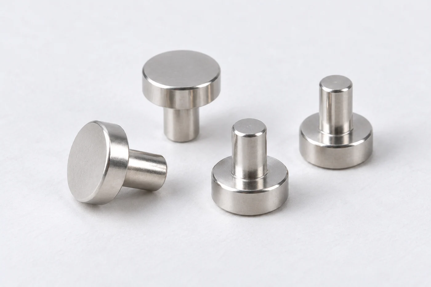
은접점 냉간 헤딩은 짧게 절단한 선재를 금형 안에서 압축해 접촉면을 가진 머리와 조립용 다리를 만드는 기술입니다. 작은 접점 안에서도 소재는 균일하게 움직이지 않습니다. 선재의 조질과 절단 체적, 예비 형상과 금형 정렬이 머리 두께·편심·표면 상태를 결정하고, 그 결과가 후속 리벳팅과 전기적 접촉 품질로 이어집니다.
정밀한 접점 제작은 외형을 맞추는 일에서 끝나지 않습니다. 접촉면의 기능과 다리의 체결 여유를 기준으로 소재·공정·검사 조건을 연결해야 합니다. 순은과 은합금의 성형성, 단계별 유동, 균열과 접힘, 치수 측정과 세정·포장까지 함께 관리하면 조립 현장에서 요구하는 품질을 구체적인 제작 사양으로 정리할 수 있습니다.
01은접점 냉간 헤딩의 원리와 기능 형상
은접점 냉간 헤딩은 은 또는 성형에 적합한 은계 접점 선재를 일정 길이로 절단하고, 금형 안에서 압축해 접점의 머리와 다리를 만드는 소성가공입니다. 소재를 깎아 머리를 남기는 대신, 다리보다 큰 지름이 필요한 부분으로 금속을 이동시킵니다. 접촉면과 조립용 다리가 하나의 부품 안에서 연결되므로 형상 정밀도와 재료 상태를 함께 관리해야 합니다.
리벳형 접점의 머리는 상대 접점과 맞닿는 기능면을 지지하고, 다리는 프레스 가동편이나 단자판에 끼워 체결하는 위치가 됩니다. 머리 지름만 맞아도 되는 구조가 아닙니다. 머리 두께와 접촉면의 높이, 다리 축과 머리 중심의 관계, 머리 아래 받침면이 조립 후의 접촉 위치에 영향을 줍니다.
접점 제조와 조립 리벳팅의 구분
헤딩은 독립된 접점 부품을 만드는 공정이고, 리벳팅은 그 접점을 지지판에 고정하는 후속 공정입니다. 헤딩에서 미리 만든 머리를 지지한 상태로 다리 끝을 성형하면 체결부가 만들어집니다. 두 공정은 모두 압축 변형을 이용하지만, 변형시키는 위치와 확보해야 할 기능이 다릅니다.
접촉면이 평평한 형상은 낮은 원통형 머리와 일정한 두께, 필요한 모서리 반경으로 정의합니다. 완만한 곡면이 필요한 형상은 곡률과 높이를 별도로 지정합니다. 외관을 임의로 둥글게 만드는 것보다 상대 접점과의 맞물림, 가동 기구의 이동 방향과 검사 기준에 맞추는 것이 중요합니다.
냉간 성형에서는 외부 가열을 주된 성형 수단으로 사용하지 않지만 변형과 마찰로 소재·공구 온도가 올라갈 수 있습니다. 따라서 가공 전후의 온도 상태와 윤활, 생산 속도를 함께 관리합니다. 형상이 완성되었다는 사실만으로 완성 스위치의 정격이나 개폐 수명이 결정되지는 않습니다.
02순은·은합금 선재의 재질과 성형성
접점 재질은 전기적 사용 조건과 냉간 성형 조건을 함께 만족해야 합니다. 순은은 높은 전기·열전도성과 연성을 갖지만, 실제 개폐에서는 접촉력과 부하에 따른 용착·마모도 검토합니다. AgCu와 AgNi 등은 조성과 조직에 따라 기계적 특성과 전기적 거동이 달라지므로 재질 이름만으로 성형 조건을 공통 적용하지 않습니다.
| 재료 계열 | 성형 검토의 출발점 | 함께 확인할 항목 |
|---|---|---|
| 순은·미세립 은계 | 공급 선재의 연성과 표면 상태 | 조질·결정립·가공 후 경도 |
| AgCu계 | 조성 및 가공·열처리 이력 | 강도·연신율·균열 민감도 |
| AgNi계 | 은 기지와 니켈 분산 조직 | 함량·분산 상태·선재 방향성 |
| AgSnO₂ 등 산화물 분산계 | 성형용 선재의 제조 경로와 적합성 | 입자 분포·연성·압축 성형 결과 |
| AgW 등 고융점 분산계 | 분말 공정과 공급 제품 형태 | 선재 헤딩 경로의 적용 가능 여부 |
조성과 공급 상태의 동시 관리
AgNi는 단순히 은에 니켈이 균일하게 녹아 있는 재료로 다루지 않습니다. 은 기지 안의 니켈 분포와 가공 방향에 따른 조직이 변형에 관여합니다. 산화물 분산계도 입자의 양과 분포, 제조 공정이 성형성에 영향을 줍니다. 성형 가능한 AgSnO₂ 선재와 리벳이 존재하지만 모든 산화물 접점재를 같은 변형률로 가공할 수 있다는 의미는 아닙니다.
AgW와 같은 재료는 소결·함침 등 별도의 제조 경로와 제품 형태를 먼저 확인합니다. 재료 명칭에 은이 포함된다는 이유로 연성이 큰 은 선재와 같은 냉간 헤딩 공정을 적용하면 안 됩니다. 소재 선정 단계에서 사용 가능한 공급 형태와 성형용 등급을 명확히 해야 합니다.
선재의 소둔 상태와 인발량은 초기 경도·강도·연신율을 바꿉니다. 같은 조성이라도 초기 상태가 달라지면 동일한 펀치 이동에서 하중과 머리 외주 변형이 달라질 수 있습니다. 재질 성적서, 선재 치수, 조질과 압축 시험 결과를 함께 묶어 양산 조건을 설정합니다.
03선재 표면·직진도와 절단면 품질
작은 접점일수록 선재 단계의 편차가 완성 형상에서 크게 드러납니다. 선경과 진원도는 투입 체적에 영향을 주고, 코일에서 풀린 선재의 휨은 이송과 절단 위치를 흔듭니다. 표면에 길게 이어진 흠이나 접힘은 압축 과정에서 벌어지거나 내부로 말려 들어갈 수 있습니다. 헤딩이 선재 결함을 자동으로 제거하지는 않습니다.
| 입고·전처리 항목 | 확인 내용 | 성형과의 연결 |
|---|---|---|
| 선경·진원도 | 위치와 방향을 바꾼 지름 측정 | 투입 체적과 다리 치수 |
| 표면 건전성 | 연속 흠·접힘·부착 이물 | 머리 외주 균열과 표면 전사 |
| 직진도·이송 상태 | 잔류 곡률·가이드 정렬·미끄럼 | 절단 길이와 금형 진입 위치 |
| 절단면 | 기울기·눌림·버·전단 흔적 | 초기 접촉과 비대칭 압축 |
| 조질·청정도 | 기계적 성질·윤활 잔류·오염 | 성형 하중과 후속 세정 |
절단 슬러그의 길이와 단면
절단된 짧은 소재를 슬러그라고 합니다. 길이가 일정해도 절단면 한쪽이 심하게 눌리거나 비스듬하면 펀치가 닿는 순간의 하중 분포가 달라집니다. 이 편차는 초기 소재의 기울어짐과 비대칭 유동으로 이어질 수 있습니다. 절단 날과 지지부, 이송 정지 위치를 함께 확인해야 합니다.
길이 측정과 질량 확인은 서로 보완합니다. 질량은 투입량 이상을 찾는 데 유용하지만, 같은 질량 안에서도 기울어진 단면이나 선경 편차가 존재할 수 있습니다. 반대로 길이만 관리하면 선경 변화에 따른 체적 변화를 놓치기 쉽습니다. 조성이 같은 로트 안에서 길이·선경·질량의 관계를 확인합니다.
선재 교정은 이송을 안정시키는 만큼의 변형으로 관리합니다. 과도한 교정이나 가이드 마찰은 표면 흠과 추가 가공경화를 만들 수 있습니다. 공급 코일을 바꾸거나 절단 날을 교체한 직후에는 첫 성형품의 중심, 외주와 다리 상태까지 이어서 확인합니다.
04절단 체적과 머리·다리의 재료 배분
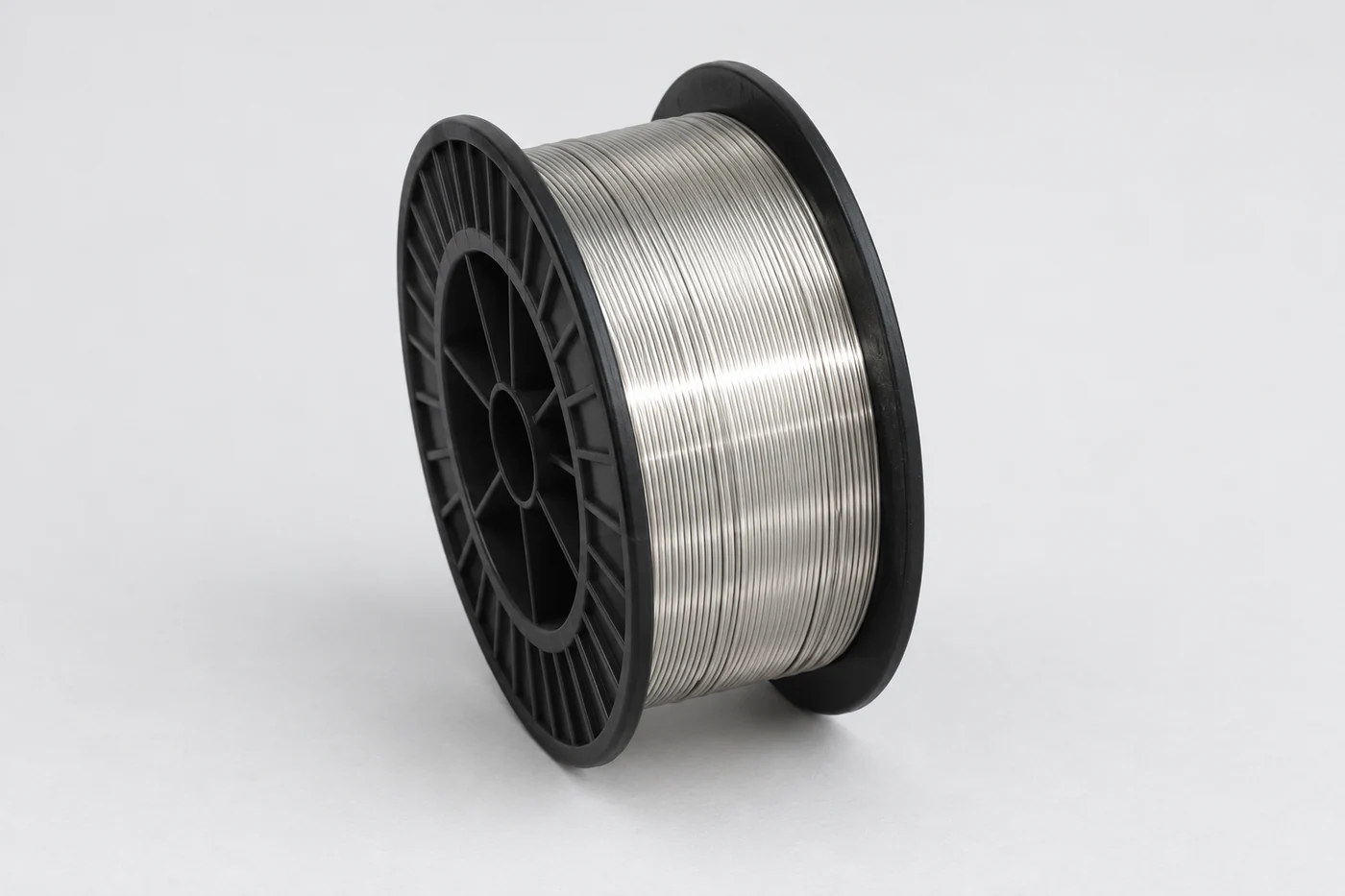
은접점 냉간 헤딩의 투입량은 머리와 다리에 필요한 체적에서 출발합니다. 치밀한 금속의 소성 변형에서는 체적 변화가 작으므로, 제거되는 재료가 없는 구간은 성형 전후 체적을 거의 같게 두고 계산할 수 있습니다. 머리를 더 넓게 만들려면 그에 필요한 소재가 있어야 하며, 압력을 높이는 것만으로 부족한 체적을 채울 수는 없습니다.
선재 지름을 d₀, 절단 길이를 L₀라고 하면 투입 체적은 V₀ = πd₀²L₀/4입니다. 머리를 지름 D·두께 h의 원통, 머리 아래 다리를 지름 d·길이 l의 원통으로 단순화하면 V₀ ≈ πD²h/4 + πd²l/4로 정리할 수 있습니다. 다리 길이 l은 머리 아래부터 측정하여 머리 체적을 중복 계산하지 않습니다.
선경 편차와 형상 오차의 연결
선경과 다리 지름이 같은 단순 형상에서는 L₀ ≈ l + (D/d)²h입니다. 실제 설계에는 모서리 반경, 목 부분의 필릿, 표면 곡률과 후속 가공량을 반영합니다. 중공 다리나 단차가 있으면 해당 체적을 따로 더하거나 빼야 합니다. 이 관계는 재료 배분을 점검하는 출발점이지 완성품 치수를 보장하는 식은 아닙니다.
체적은 선경의 제곱에 비례합니다. 작은 변화에 대해 ΔV/V ≈ 2Δd₀/d₀ + ΔL₀/L₀로 볼 수 있으므로, 길이가 일정할 때 선경이 약 0.5% 증가하면 투입 체적은 약 1% 증가합니다. 실제 증가분이 머리 지름, 두께 또는 다른 부위에 나타나는지는 금형 구속과 유동 경로에 따라 달라집니다.
투입량이 부족하면 머리 외곽이나 모서리의 충진이 모자랄 수 있고, 지나치면 과도한 하중이나 틈새로의 재료 유출이 발생할 수 있습니다. 다만 같은 외관도 스트로크·윤활·금형 마모가 원인일 수 있습니다. 슬러그 체적과 금형 상태를 함께 확인한 뒤 조정해야 원인을 분리할 수 있습니다.
05예비 성형과 마무리 헤딩의 공정 구성
절단한 소재를 한 번에 최종 형상으로 누를 수 있는지는 머리와 다리의 비율, 소재 상태, 금형 지지 조건에 따라 달라집니다. 큰 머리를 만드는 과정에서는 예비 성형으로 소재를 안정적으로 펼친 뒤 마무리 성형으로 두께와 외곽을 정하는 방식이 유리할 수 있습니다. 두 번 또는 여러 단계의 성형은 금속의 이동 경로를 나누어 제어하는 수단입니다.
| 공정 단계 | 형상 변화 | 관리할 상태 |
|---|---|---|
| 정량 이송·절단 | 연속 선재를 일정 체적의 슬러그로 분리 | 선경·길이·절단면 |
| 위치 결정·지지 | 성형축과 소재축을 정렬 | 다리 지지·돌출 길이 |
| 예비 업세팅 | 길이를 줄이며 머리용 소재를 펼침 | 중심 유지·자유면 변형 |
| 마무리 헤딩 | 접촉면·머리 두께·외곽 형성 | 충진·하중·금형 맞물림 |
| 이형·배출 | 성형품을 금형에서 분리 | 머리 눌림·다리 휨·배출 흠 |
단계 수보다 중요한 중간 형상
예비 성형품의 윤곽은 다음 단계에서 금속이 접히지 않고 목적 위치로 이동하도록 설계합니다. 돌출부가 길고 지지가 부족하면 축 방향으로 줄어드는 대신 옆으로 휘어질 수 있습니다. 소재와 형상에 맞춰 돌출 길이, 펀치 형상과 지지 위치를 함께 정하며, 다른 재료에서 쓰는 길이 비율을 그대로 옮기지 않습니다.
머리 끝까지 억지로 한 번에 채우면 외주 변형과 금형 하중이 집중될 수 있습니다. 반대로 단계만 늘리고 중간 형상을 바꾸지 않으면 문제를 다음 공정으로 전달할 수 있습니다. 공정 설계는 각 단계의 체적 배분, 접촉 면적, 변형량과 이송 안정성을 묶어 검토해야 합니다.
이형과 배출도 형상 품질의 일부입니다. 얇은 머리를 한쪽에서 밀거나 다리를 비스듬히 빼면 성형 직후에 변형이 추가될 수 있습니다. 완성품 검사에서 발견한 휨이나 눌림은 헤딩 구간뿐 아니라 이젝터·이송·수집 과정까지 따라가며 원인을 확인합니다.
화살표 키로 시점 조절
같은 조성의 솔리드 접점은 선재 절단편의 일부가 다리로 남고, 돌출된 구간이 압축되어 머리를 이룹니다. 절단 길이는 완성 형상의 체적과 후공정 여유를 함께 고려합니다.
솔리드 접점의 소재 체적을 유지한 축방향 압축과 머리 형성
06금형의 지지·정렬과 하중 관리
헤딩 금형은 단순히 외형을 찍는 틀이 아니라 소재가 움직일 수 있는 방향을 정하는 장치입니다. 다이 구멍은 다리 부분을 지지하고, 펀치는 돌출된 소재를 압축합니다. 지지 위치와 간극이 바뀌면 같은 슬러그와 스트로크에서도 머리와 목 부분의 유동이 달라집니다. 완성품이 요구하는 기능면을 기준으로 공구 구조를 정해야 합니다.
펀치와 다이의 축이 맞지 않으면 머리 중심이 다리 축에서 벗어나거나 한쪽 두께가 달라질 수 있습니다. 절단·이송 편차도 비슷한 현상을 만들기 때문에 공구 정렬만 확인하고 끝내지 않습니다. 부하를 받기 전의 정렬과 실제 성형 하중에서의 처짐, 지지 강성을 구분해 검토합니다.
하중·변위 신호의 해석
성형 하중은 소재의 유동응력, 변형 면적과 구속 상태, 윤활 및 변형 이력에 따라 달라집니다. 경도나 인장강도 하나만으로 정확한 헤딩 하중을 환산할 수는 없습니다. 소재의 압축 거동과 공정별 변형을 반영하고, 설비의 허용 하중·에너지·강성 범위와 함께 판단합니다.
하중과 변위의 변화는 소재 공급 이상, 윤활 변화나 공구 상태를 찾는 단서가 됩니다. 같은 최종 하중이라도 중간에 급격한 변화가 있는 공정과 부드럽게 증가하는 공정은 다른 유동을 가질 수 있습니다. 센서 위치와 장비 탄성 변형이 기록에 포함되는 만큼, 신호를 실제 제품 치수·단면과 대조해 판정 기준을 만듭니다.
마모된 다이 구멍이나 펀치 끝단의 작은 손상은 다리 치수와 접촉면에 반복적으로 전사될 수 있습니다. 특정 위치에서 반복되는 흠은 소재 불량과 공구 손상을 구분하는 데 도움이 됩니다. 금형 교체 후에는 마지막 양품과 첫 생산품을 연결해 확인하고, 조정으로 보상한 편차가 다른 치수에 영향을 주지 않는지도 검사합니다.
화살표 키로 시점 조절
다이가 다리가 되는 구간을 안내하고, 아래쪽 지지부가 축방향 힘을 받습니다. 상부에 남긴 소재를 펀치가 압축하도록 절단편의 위치와 돌출량을 관리합니다.
다이와 펀치의 단면에서 확인하는 지지·압축·복귀 위치
07마찰·가공경화와 미세 조직의 영향
금형과 맞닿은 금속은 마찰 때문에 자유롭게 미끄러지지 못합니다. 상대적으로 움직이기 쉬운 영역과 구속된 영역의 차이가 커지면 변형이 불균일해지고, 자유면이 볼록해지는 배럴링이나 국부 유동 집중이 나타날 수 있습니다. 형상 변화는 펀치 이동량뿐 아니라 소재와 공구 사이의 접촉 조건에 의해 결정됩니다.
윤활은 마찰과 응착을 줄이고 공구 표면을 보호하지만, 전기접점에서는 후속 세정과 표면 청정도까지 연결해 선택해야 합니다. 성형이 잘되는 윤활제라도 제거가 어렵거나 잔류물이 접촉면·접합면에 남으면 후공정 부담이 커집니다. 도포량과 공급 안정성, 소재·공구와의 적합성 및 제거 공정을 한 묶음으로 관리합니다.
머리와 다리의 서로 다른 변형 이력
냉간 변형이 누적되면 가공경화로 유동에 필요한 응력이 증가할 수 있습니다. 크게 펼쳐진 머리와 금형에 지지된 다리는 변형 이력이 같지 않으므로 경도도 위치에 따라 달라질 수 있습니다. 다리가 항상 부드럽게 남는다고 단정하기보다, 후속 리벳팅에 필요한 변형 여유를 실제 위치별 상태로 확인합니다.
소재가 작아질수록 부품 치수에 대한 결정립 크기의 비율이 중요해집니다. 단면 안의 결정립 수가 적어지면 평균적인 재료 특성만으로 국부 변형과 표면 거칠어짐을 충분히 설명하기 어려울 수 있습니다. 소형 접점은 큰 부품의 형상과 공정 조건을 단순 축소하기보다 선재 조직과 표면 상태를 함께 확인해야 합니다.
열처리를 추가할 때는 연성 회복만 보지 않습니다. 경도, 결정립, 접촉층과 복합재 계면, 후속 조립 거동까지 함께 바뀔 수 있습니다. 소재 조성과 제조 경로에 맞춰 열이력을 정하고, 성형 전후 및 최종 상태의 특성을 구분해 관리합니다. 성형 해석도 실제 압축 물성과 마찰 조건으로 검증해야 유효합니다.
08균열·접힘·편심·충진 부족의 원인 구분
머리 외주에 생긴 균열을 보고 성형 하중만 낮추거나, 작은 머리를 보고 절단 길이만 늘리는 방식은 원인을 놓치기 쉽습니다. 소재 결함, 초기 조질, 공정별 변형량, 정렬과 윤활은 서로 영향을 줍니다. 결함의 위치·방향·반복성을 기록하고 정상품과 같은 절단·관찰 조건으로 비교해야 합니다.
| 관찰 현상 | 검토할 원인 | 추가 확인 |
|---|---|---|
| 머리 외주 균열 | 성형 한계·선재 흠·국부 변형 집중 | 선재 표면·경도·성형 단계별 외주 |
| 접힘·랩 | 좌굴·부적절한 예비 형상·비대칭 유동 | 중간 형상·단면·지지 상태 |
| 머리 편심 | 공구축·이송·절단면의 불균형 | 다리 축 기준 측정·반복 방향 |
| 충진 부족 | 체적 부족·스트로크·마찰·공구 상태 | 슬러그 질량·길이·금형 윤곽 |
| 표면 눌림·끌림 | 공구 손상·응착·이형·제품 간 충돌 | 발생 위치·공구 표면·배출 경로 |
표면 흔적과 내부 불연속
랩은 금속 표면이 접혀 들어가 생기는 불연속입니다. 외관에서 가는 선으로 보이거나 표면 아래에 남을 수 있으며, 단순 연마로 겉을 매끈하게 만든다고 내부가 건전해지는 것은 아닙니다. 의심되는 위치는 절단 방향을 정해 단면을 관찰하고, 실제 접촉면·목·체결부에 미치는 영향을 평가합니다.
금형 접촉 흔적과 균열도 구분해야 합니다. 조명 방향에 따라 보였다 사라지는 선, 깊이가 있는 균열, 표면에 눌린 자국은 의미가 다릅니다. 확대 관찰, 표면 형상 측정과 단면 검사를 조합해 판정하고, 합격 외관 한도를 기능면과 비기능면별로 정합니다.
원인 확인은 원소재에서 완성품으로 이어지는 순서가 효율적입니다. 선재와 슬러그를 먼저 대조하고, 예비 성형품에서 결함이 시작되는 단계와 최종 성형에서 확대되는 정도를 봅니다. 한 번에 여러 조건을 바꾸기보다 변경 항목과 결과를 연결해 다음 로트에도 재현할 수 있는 관리 조건으로 남깁니다.
09기능 치수와 측정 기준의 설계
은접점 냉간 헤딩의 치수 검사는 전체 외형을 재는 것에서 시작해 조립 기능을 확인하는 방향으로 이어집니다. 머리 지름과 다리 지름, 머리 두께, 머리 아래 길이, 전체 높이는 서로 연결되지만 같은 값이 아닙니다. 측정 기준을 도면에 명확히 두어 머리 두께 변화가 다리 길이 변화로 잘못 해석되지 않도록 합니다.
| 기능 치수 | 연결되는 기능 | 측정 시 유의점 |
|---|---|---|
| 머리 지름·윤곽 | 접촉면 범위와 주변 부품 간격 | 모서리 반경과 실제 외주를 구분 |
| 머리 두께·접촉면 높이 | 접점 맞물림과 가동량 | 접촉면의 곡률·기준면 지정 |
| 다리 지름·길이 | 판 구멍 삽입과 리벳팅 여유 | 머리 아래 길이와 전체 높이 구분 |
| 머리·다리 축 관계 | 조립 후 접촉 위치 | 다리 축과 기능면 기준 설정 |
| 받침면·목 반경 | 지지판 안착과 국부 변형 | 구멍 입구·모따기와의 간섭 확인 |
측정력과 관찰 방향의 영향
얇고 비교적 연한 머리는 측정력이나 지지 방식에 따라 눌리거나 기울어질 수 있습니다. 마이크로미터의 접촉 조건, 영상 측정의 조명·초점·윤곽 검출 기준을 고정합니다. 은색 표면의 반사를 실제 모서리로 인식하면 값이 흔들릴 수 있어 측정 방향과 광학 조건을 함께 관리해야 합니다.
다리 축을 기준으로 머리 중심을 확인하면 전체 높이 검사만으로 놓치는 편심을 찾을 수 있습니다. 다만 외주가 원형이라는 이유로 접촉면이 다리에 수직이라고 볼 수는 없습니다. 필요한 위치도·직각도·평행도 등은 조립 기능에 맞게 지정하고, 측정 장비와 고정구가 그 기준을 재현할 수 있어야 합니다.
검사 장비의 반복성과 측정자 간 차이는 제품 공차에 비해 충분히 작아야 합니다. 초도품을 합격시킨 측정 방법과 양산 검사 방법이 다르면 공정 변화를 판단하기 어렵습니다. 도면 판본, 측정 프로그램, 조명 조건과 한도 견본을 함께 관리해 공급자와 조립 현장의 판단을 연결합니다.
화살표 키로 시점 조절
머리 외경과 두께는 접촉 위치와 조립 높이에 연결됩니다. 외경이 같더라도 면의 평탄도와 모서리 형상이 다르면 기능면의 상태가 달라질 수 있습니다.
머리 외경·두께와 다리 기준축을 구분한 형상 검사
10접촉면 마감·세정과 후처리 관리
접점 표면은 보기 좋은 광택과 전기적으로 안정적인 접촉을 구분해 관리합니다. 거울처럼 반짝이는 외관이 낮은 접촉저항을 보증하지는 않습니다. 표면의 기복과 흠, 가공 잔류물, 변색과 오염은 실제 맞닿는 미세 영역에 영향을 줍니다. 기능면에 필요한 조도와 외관 한도는 상대 접점·접촉력·작동 방식에 맞춰 정합니다.
헤딩 펀치의 표면은 접촉면에 전사됩니다. 공구의 연마 방향, 응착물과 마모를 관리하고, 필요한 경우 후속 마감으로 외관과 표면 상태를 정리합니다. 이때 연마량이 머리 두께·접촉면 곡률·모서리 반경을 바꾸지 않는지 확인해야 합니다. 표면을 균일하게 보이게 만드는 작업도 기능 치수를 건드릴 수 있습니다.
잔류물 제거와 재오염 방지
세정은 윤활제와 금속 입자를 제거하고 건조·보관으로 이어지는 공정입니다. 은계 소재와 접합 구조에 맞는 세정제를 선정하고, 세정 후 잔류물과 수분이 남지 않도록 관리합니다. 은 표면의 황화 변색은 주변 물질과 포장 환경의 영향을 받을 수 있으므로, 접촉재와 맞닿는 포장재·취급 도구까지 확인합니다.
도금이 필요한 접점은 적용 면과 목적을 먼저 정합니다. 모든 은접점을 도금하는 것은 아니며, 도금으로 성형 균열이나 접합 결함을 해결할 수는 없습니다. 피막을 추가하면 치수와 표면의 기계·전기적 상태가 달라지므로 두께와 밀착성, 기능면 상태를 후처리 이후에 다시 확인합니다.
제품끼리 강하게 부딪히는 수집·이송은 얇은 머리의 눌림과 가장자리 흠을 만들 수 있습니다. 검사가 끝난 접점도 보관 중에 오염되거나 손상될 수 있어 수집 용기, 공정 간 이동과 최종 포장을 함께 설계합니다. 완성품 품질은 마지막 성형 스트로크가 아니라 조립 현장에 도착한 표면 상태까지 이어집니다.

11솔리드 접점과 클래드 접점의 성형 차이
솔리드 접점은 머리와 다리를 하나의 접점재 계열로 구성합니다. 클래드 접점은 기능면에 은 또는 은합금 접촉재를 배치하고, 지지부와 다리에 구리계 재료 등을 사용하는 복합 구조입니다. 두 구조는 외형이 비슷해도 투입 소재와 접합 계면, 변형 이력 및 검사 항목이 다릅니다.
복합 접점은 접촉재와 기재의 선재 또는 소재를 정량 공급하고, 접합에 적합한 표면과 변형 조건에서 압접·성형하는 경로를 사용할 수 있습니다. 냉간 압접에서는 접합면의 오염과 표면 상태, 압력과 소성 유동이 중요합니다. 서로 다른 금속을 겹쳐 누르기만 하면 안정적인 계면이 자동으로 만들어지는 것은 아닙니다.
층 두께와 계면 건전성
최종 접촉층 두께는 초기 투입량에 더해 성형 중 재료가 퍼지는 방식에 따라 달라집니다. 중심과 외주, 접촉면 가까운 위치를 구분하여 단면을 관찰하고, 요구 위치에서 층이 연속적으로 남는지 확인합니다. 외관에서 보이는 색 경계나 띠 폭만으로 내부 접촉재의 분포와 접합 상태를 판정하지 않습니다.
층 두께와 기재 비율은 접촉재 조성, 형상, 개폐 조건과 요구 수명에 맞춰 지정합니다. 특정 비율을 모든 클래드 접점의 정의처럼 적용하지 않습니다. 접촉층이 얇아지는 위치, 과도하게 흐른 부위, 계면의 미접합·공극을 검사하고 후속 리벳팅이나 열공정 뒤에도 건전성이 유지되는지 확인합니다.
클래드 계면은 부품 내부의 결합 경계이며 외주에 홈이나 벌어진 틈을 만드는 구조가 아닙니다. 형상 도면에서는 접촉층과 기재의 위치를 명확히 하고, 실제 제품의 외관·단면 검사에서는 의도한 재료 경계와 결함을 구분합니다. 솔리드 접점용 조건을 복합재에 그대로 옮기지 않는 이유가 여기에 있습니다.
12프레스 부품과의 조립을 고려한 접점 설계
헤딩 접점은 프레스 가동편이나 단자판에 조립된 뒤 기능합니다. 다리 지름과 판 구멍, 머리 아래 반경과 구멍 입구, 판 두께와 돌출 길이를 함께 검토해야 합니다. 접점 자체가 도면에 맞아도 지지판의 버나 휨, 구멍 위치 편차가 있으면 받침면이 고르게 안착하지 않을 수 있습니다.
리벳팅에서는 기존 접촉면을 손상시키지 않도록 지지하고, 돌출 다리에 필요한 성형량을 부여합니다. 돌출 길이가 부족하면 체결에 필요한 형상을 만들기 어렵고, 과도하면 접힘이나 지지판 변형을 유발할 수 있습니다. 접점의 초기 경도와 단면 구조가 다리의 퍼짐에 미치는 영향도 확인합니다.
기계적 결합과 전기적 연결
머리가 흔들리지 않는다고 전기적 접합이 충분한 것은 아니며, 낮은 저항만으로 반복 하중에 대한 체결 신뢰성을 판단할 수도 없습니다. 회전·푸시 아웃·전단 등 구조에 맞는 기계 검증과 전기저항 측정을 구분합니다. 전기 측정은 접점-판 접합부와 상대 접점 사이의 접촉부를 나누어 측정 위치를 정해야 원인을 해석할 수 있습니다.
용접이나 브레이징으로 부착하는 접점은 후면 형상, 접합 가능한 기재와 열이력을 별도로 설계합니다. 리벳형 접점의 다리를 없애기만 하면 용접형 버튼과 같은 부품이 되는 것은 아닙니다. 접합 과정의 열과 힘이 접촉층, 가동편의 탄성 및 접점 높이에 미치는 영향을 확인합니다.
조립 후에는 맞닿는 위치와 접촉력, 개방 간극과 반복 작동을 점검합니다. 헤딩 부품의 합격과 조립품의 합격은 서로 연결되지만 별도의 검증입니다. 소재 성적, 형상 검사와 접합 결과가 완성 기구의 시험 조건까지 이어져야 공급 사양이 명확해집니다.
13초도 승인·양산 관리와 제작 사양
은접점 냉간 헤딩의 양산 관리는 최종 선별만으로 완성되지 않습니다. 소재 로트, 선재 조질, 절단·성형 공구, 윤활과 세정 조건을 연결해 관리해야 편차가 생겼을 때 원인을 추적할 수 있습니다. 초도품 승인에서는 외형뿐 아니라 필요한 단면, 표면 상태와 후속 조립성을 함께 확인합니다.
| 관리 단계 | 확보할 정보 | 판단 목적 |
|---|---|---|
| 소재 입고 | 재질·조성·조질·선경·로트 | 성형용 소재의 일관성 |
| 초도 성형 | 슬러그·중간 형상·완성 치수 | 투입량과 금형 조건 승인 |
| 공정 중 검사 | 치수 추이·외관·하중 변화 | 마모·이송·윤활 변화 감지 |
| 후처리·출하 | 청정도·피막·포장·식별 | 조립 시점의 기능 상태 유지 |
| 변경 관리 | 소재·공구·열처리·세정 변경 이력 | 기존 승인 조건과의 차이 검증 |
형상 공차와 기능 요구의 연결
제작 검토에는 머리·다리 치수와 기준면, 접촉면 윤곽, 목 반경, 재질과 공급 상태가 필요합니다. 클래드 구조라면 층의 위치와 요구 두께, 계면 검사 조건도 포함합니다. 후속 부착 방식과 상대 부품의 구멍·판 두께를 함께 전달하면 접점 단품의 치수를 조립 기능에 맞춰 검토할 수 있습니다.
검사 주기는 부품의 기능 위험과 공정 변동에 맞춰 정합니다. 공구 교체·코일 변경·장시간 정지 후 재가동은 안정 생산 중과 다른 확인이 필요할 수 있습니다. 치수 평균뿐 아니라 산포와 시간에 따른 추이를 보고, 광학 전수 선별을 적용해도 검출하지 못하는 내부 결함과 재료 상태는 별도 검사로 보완합니다.
공정능력 지수는 안정된 공정과 적합한 측정 시스템을 전제로 해석합니다. 소량 초도품 몇 개가 공차 안에 들어왔다고 장기 양산 능력이 입증되는 것은 아닙니다. 측정 방법과 표본 조건, 이상 발생 시 격리 범위를 합의하고, 변경 후에는 영향을 받는 기능 항목을 다시 확인합니다.
정밀 은접점은 재료와 형상이 함께 완성되는 부품입니다. 선재의 성형성, 단계별 체적 이동, 접촉면과 다리의 기능 치수, 세정·취급 및 지지판과의 접합을 연결하면 제조 기준이 분명해집니다. 도면과 사용 조건을 바탕으로 이 연결 관계를 정리하는 것이 안정적인 접점 제작의 출발점입니다.
Silver Contact Cold Heading: From Wire Forming to Precision Rivet Quality
Silver contact cold heading compresses a measured wire segment in tooling to form a working head and an assembly shank. Even in a small rivet, the metal does not move uniformly. Wire condition, cutoff volume, preform geometry and tool alignment determine head thickness, eccentricity and surface condition, connecting the forming process to later riveting and electrical contact quality.
Precision manufacture goes beyond matching an outline. Material, process and inspection conditions must follow the function of the working face and the allowance needed to fasten the shank. Reviewing silver-alloy formability, staged flow, cracks and laps, dimensional measurement, cleaning and packaging translates assembly requirements into a practical manufacturing specification.
01Cold heading and the functional geometry of a contact rivet
Cold heading converts silver or a formable silver-based contact wire into a rivet with a head and shank. A measured wire segment is cut off and compressed in tooling so that metal moves into the larger head diameter. The process connects a functional contact face and an assembly shank within one component, making material condition as important as dimensional control.
The head supports the working face that meets the opposing contact. The shank locates the component in a stamped arm or terminal plate. Head diameter alone is insufficient: head thickness, face height, head-to-shank alignment and the underside seating surface all affect the final contact position after assembly.
Contact manufacture and attachment riveting
Heading manufactures the separate contact rivet. Attachment riveting is a later operation that fixes it to a carrier. With the existing head supported, deformation of the projecting shank end creates the fastening. Both operations use compression, but they deform different regions and must deliver different functions.
A flat contact face is defined through a low cylindrical head, controlled thickness and specified edge radii. Where a gently curved face is required, its curvature and height are specified separately. Geometry should follow the mating contact, mechanism movement and inspection datum rather than an arbitrary rounded appearance.
Cold forming does not use external heating as its principal forming mechanism, but plastic deformation and friction can still raise workpiece and tool temperatures. Temperature condition, lubrication and production speed therefore remain process variables. A successfully formed rivet does not by itself establish the electrical rating or switching life of the complete device.
02Silver-based wire materials and cold formability
The material must satisfy electrical service requirements and the proposed forming route. Fine silver combines high electrical and thermal conductivity with ductility, while welding and wear in service still depend on contact force and load. AgCu and AgNi grades differ in composition and structure, so a common material name does not justify identical heading settings.
| Material family | Starting point for forming review | Associated checks |
|---|---|---|
| Fine silver and fine-grain silver | Wire ductility and surface condition | Temper, grain structure and final hardness |
| AgCu | Composition and working/heat-treatment history | Strength, elongation and crack sensitivity |
| AgNi | Silver matrix and nickel dispersion | Content, distribution and wire directionality |
| Oxide-dispersed grades such as AgSnO₂ | Manufacturing route and suitability of heading wire | Particle distribution, ductility and compression results |
| Refractory composites such as AgW | Powder route and supplied product form | Whether wire heading is an applicable route |
Composition and supplied condition
AgNi should not be treated as silver containing a completely uniform solid solution of nickel. Nickel distribution within the silver matrix and the worked microstructure influence deformation. Oxide-dispersed materials also depend on particle content, distribution and production route. Formable AgSnO₂ wire and rivets exist; this does not mean that every oxide contact grade tolerates the same deformation.
For materials such as AgW, first establish the powder-processing route, including sintering or infiltration where applicable, and the available product form. The presence of silver in a material name does not make it equivalent to a highly ductile silver wire. The supplied form and grade must be defined before assigning a heading route.
Annealing condition and prior wire reduction change initial hardness, strength and elongation. Even with the same composition, a different starting condition can alter load and head-edge deformation at an identical punch displacement. Material certification, wire dimensions, temper and compression-test results belong together when setting production conditions.
03Wire surface, straightness and cut-end quality
As contacts become smaller, incoming wire variation becomes more visible in the finished geometry. Diameter and roundness affect input volume, while residual coil curvature disturbs feeding and cutoff position. Longitudinal damage or folded surface material can open during upsetting or become buried in a fold. Heading does not automatically remove defects from the wire.
| Incoming or preparation item | Inspection focus | Connection to forming |
|---|---|---|
| Diameter and roundness | Measurements at different positions and orientations | Input volume and shank dimensions |
| Surface integrity | Continuous damage, folds and attached particles | Head-edge cracking and transferred marks |
| Straightness and feeding | Residual curvature, guide alignment and slip | Cutoff length and die-entry position |
| Cut end | Inclination, rollover, burr and shear marks | Initial loading and asymmetric compression |
| Temper and cleanliness | Mechanical condition, lubricant residues and contamination | Forming load and subsequent cleaning |
Slug length and the cut section
The short cutoff piece is the slug. Even at a constant overall length, a heavily rolled-over or inclined cut end changes the load distribution when the punch first touches it. This can initiate tilting and asymmetric flow. Cutoff tooling, wire support and the feed stop therefore need to be reviewed together.
Length and mass measurements complement one another. Mass can reveal an input-quantity anomaly, but equal-mass slugs may still have different end angles or diameter variation. Length control alone can miss a volume change caused by wire diameter. Compare length, diameter and mass within a lot of the same composition.
Straightening should provide the deformation needed for stable feeding. Excessive straightening or guide friction can introduce surface damage and additional work hardening. After a coil change or cutoff-tool replacement, extend the first-piece check to head centering, perimeter condition and the shank of the formed part.
04Cutoff volume and allocation between head and shank
Input quantity for silver-contact cold heading starts with the volume required by the head and shank. Dense metal changes volume only slightly during plastic deformation, allowing approximate volume conservation through stages that remove no material. A wider head requires an adequate allocation of metal; higher pressure cannot replace missing volume.
For wire diameter d₀ and cutoff length L₀, the initial volume is V₀ = πd₀²L₀/4. Approximating the head as a cylinder of diameter D and thickness h, and the shank below it as a cylinder of diameter d and length l, gives V₀ ≈ πD²h/4 + πd²l/4. The shank length l begins under the head so that its volume is not counted twice.
Diameter variation and resulting geometry
For the simplified case in which the wire and shank have the same diameter, L₀ ≈ l + (D/d)²h. Actual design must include edge radii, the neck fillet, face curvature and subsequent material removal. A bore or step requires its own volume correction. The relationship is a starting point for material allocation, not a guarantee of finished dimensions.
Volume is proportional to wire diameter squared. For small changes, ΔV/V ≈ 2Δd₀/d₀ + ΔL₀/L₀. At constant cutoff length, a diameter increase of approximately 0.5% therefore adds approximately 1% input volume. Whether that extra metal changes head diameter, thickness or another feature depends on tooling constraints and the flow path.
Insufficient input can leave the head perimeter or corners underfilled. Excess input can produce excessive load or force metal into a tooling gap. Similar visible symptoms may also originate in stroke, lubrication or die wear. Checking slug volume together with tooling condition helps separate causes before adjustment.
05Preforming and the finishing heading sequence
Whether a cutoff can be headed directly to its final shape depends on head-to-shank proportions, material condition and tooling support. For a larger head, a preform can spread the allocated metal before a finishing operation sets thickness and perimeter. Two-blow or multistage forming divides and controls the path of metal movement.
| Stage | Geometry change | Controlled condition |
|---|---|---|
| Measured feeding and cutoff | Continuous wire becomes a slug of specified volume | Diameter, length and cut end |
| Location and support | Workpiece and forming axes are aligned | Shank support and projection length |
| Preliminary upsetting | Length decreases as head material spreads | Centering and free-surface deformation |
| Finishing heading | Face, head thickness and perimeter are formed | Filling, load and tool closure |
| Release and ejection | The formed rivet leaves the tooling | Head indentation, shank bend and ejection marks |
Intermediate shape and process stability
The preform contour should guide metal into the required region at the next stage without folding over. A long unsupported projection may bend sideways rather than shorten along its axis. Projection length, punch profile and support location must therefore be selected for the material and geometry; ratios used for another material cannot simply be transferred.
Attempting to fill the entire head in one operation can concentrate perimeter deformation and tool load. Adding stages without improving the intermediate shape can merely pass a problem downstream. Process design must connect volume allocation, contact area, strain and stable transfer at every stage.
Release and ejection are also part of dimensional quality. Pushing a thin head from one side or withdrawing a shank at an angle can deform a newly formed rivet. A bend or indentation found in finished-part inspection should be traced through the ejector, transfer and collection sequence as well as the heading stroke.
Arrow keys change the view
In a solid contact of one composition, part of the cut wire remains as the shank while the protruding region is compressed to form the head. Cut length accounts for the finished volume and allowances for subsequent processing.
Axial compression and head formation with the solid-contact material volume conserved
06Tool support, alignment and load control
Heading tools control the directions in which material can flow, as well as the final outline. The die bore supports the shank while the punch compresses the projecting material. Changing support location or clearance can alter flow at the head and neck even with the same slug and stroke. Tool design should be tied to the functional surfaces required in the finished part.
Misalignment between punch and die can shift the head center away from the shank axis or produce unequal thickness. Cutoff and transfer errors can create similar symptoms, so a centering check alone is insufficient. Distinguish unloaded alignment from deflection and support stiffness under the actual forming load.
Interpreting load and displacement
Forming load depends on flow stress, deforming area, constraint, lubrication and prior strain. Neither hardness nor tensile strength alone converts directly into an accurate heading-force prediction. Compression behavior and stage-specific deformation must be considered together with machine load, energy and stiffness limits.
Load–displacement changes can indicate feeding anomalies, lubrication changes or tooling condition. Two cycles with the same final load can have different flow histories if one contains a sharp intermediate change. Sensor position and elastic deflection of the load system influence the record; acceptance criteria should therefore correlate the signal with measured dimensions and sections.
Wear in a die bore or small damage to a punch face can repeatedly transfer into shank dimensions or the contact face. Marks recurring at a fixed location help distinguish tooling damage from incoming-material defects. After tool replacement, compare the last acceptable parts with the first new parts and check whether a compensating adjustment has shifted another dimension.
Arrow keys change the view
The die guides the shank-forming region while the lower support reacts the axial load. Blank position and protruding length are controlled so the punch compresses the material left above the die.
Support, compression and return positions shown through sectioned die and punch bodies
07Friction, work hardening and microstructural effects
Friction prevents metal in contact with the tooling from sliding freely. Differences between mobile and constrained regions create nonuniform deformation, including barreling of a free surface or localized flow. The resulting shape depends on workpiece–tool contact conditions as well as punch travel.
Lubrication reduces friction and adhesion and protects tooling, but an electrical-contact process must also consider subsequent cleaning. A lubricant that forms well may create a downstream problem if it is difficult to remove or leaves residue on a working or joining face. Application quantity, supply consistency, compatibility and removal form one process decision.
Different strain histories in the head and shank
Accumulated cold deformation can increase the stress required for further flow through work hardening. The widely spread head and the supported shank do not share the same strain history, and their hardness can differ. Rather than assuming that the shank always remains soft, verify the local condition needed for subsequent attachment riveting.
As the part becomes smaller, grain size relative to component dimensions becomes increasingly relevant. With fewer grains across a section, average material properties may not adequately describe localized deformation or surface roughening. Small contact manufacture therefore requires wire-structure and surface checks rather than simple geometric scaling of a larger forming operation.
An added heat treatment must be evaluated beyond ductility recovery. Hardness, grain structure, functional layers, composite interfaces and later assembly behavior may also change. Define thermal history for the composition and manufacturing route, and distinguish preformed, postformed and final conditions. Forming simulations likewise need validation against appropriate compression properties and friction conditions.
08Separating cracks, laps, eccentricity and underfill
Reducing load whenever a head-edge crack appears, or increasing cutoff length whenever a head is small, can obscure the actual cause. Wire defects, starting condition, stage reduction, alignment and lubrication interact. Record defect position, direction and recurrence, then compare acceptable and suspect parts using the same sectioning and observation conditions.
| Observation | Possible contributors | Additional verification |
|---|---|---|
| Head-edge crack | Formability limit, wire damage or concentrated local strain | Wire surface, hardness and each intermediate perimeter |
| Fold or lap | Buckling, unsuitable preform or asymmetric flow | Intermediate shape, section and support |
| Eccentric head | Tool axes, transfer or unequal cut ends | Shank-datum measurement and recurring direction |
| Underfill | Input volume, stroke, friction or tooling condition | Slug mass, length and die contour |
| Indentation or drag mark | Tool damage, adhesion, release or part collisions | Location, tool surface and ejection path |
Surface marks and internal discontinuities
A lap is a discontinuity created when a metal surface folds into the material. It may appear as a fine line or remain below the visible surface. Polishing the outside smooth does not restore internal integrity. Section suspect regions in a defined orientation and assess their effect on the working face, neck and fastening region.
Tool-contact marks must also be distinguished from cracks. A line that changes with lighting, an open crack and a depressed surface mark are different observations. Combine magnified viewing, surface measurement and section inspection, then establish appearance limits separately for functional and nonfunctional regions.
A useful investigation follows the material through production. Compare wire and slugs first, identify the intermediate stage where a defect begins, and determine how finishing amplifies it. Linking individual parameter changes to results, rather than changing several conditions at once, produces control settings that can be reproduced in later lots.
09Functional dimensions and measurement datums
Dimensional inspection starts with the outline and proceeds toward assembly function. Head diameter, shank diameter, head thickness, under-head length and overall height are related but distinct quantities. Clear drawing datums prevent a change in head thickness from being mistaken for a change in shank length.
| Functional dimension | Associated function | Measurement consideration |
|---|---|---|
| Head diameter and profile | Working-face extent and nearby clearance | Separate edge radius from the actual perimeter |
| Head thickness and face height | Contact engagement and travel | Define face curvature and reference surface |
| Shank diameter and length | Insertion into the carrier and riveting allowance | Separate under-head length from overall height |
| Head-to-shank axis relationship | Contact location after assembly | Define the shank axis and functional-face datum |
| Seating surface and neck radius | Carrier seating and local deformation | Check interference with hole entry and chamfer |
Measuring force and viewing direction
A thin, relatively soft head can indent or tilt with measuring force and support arrangement. Fix the contact conditions of a micrometer and the lighting, focus and edge-detection settings of an optical measurement. Reflections from a silver surface can be mistaken for a physical edge, so viewing direction and optical conditions require consistent control.
Locating the head center relative to the shank axis reveals eccentricity that overall-height inspection misses. A round perimeter does not establish that the working face is perpendicular to the shank. Specify positional, perpendicularity or parallelism requirements according to function, and ensure the fixture and measurement system can reproduce the chosen datums.
Instrument repeatability and operator variation need to be sufficiently small relative to the product tolerance. A different inspection method for first-piece approval and routine production can obscure process drift. Keep drawing revision, measurement program, lighting conditions and limit samples connected so that the supplier and assembly operation make consistent decisions.
Arrow keys change the view
Head diameter and thickness influence contact location and assembly height. Even with the same diameter, face flatness and edge form can change the condition of the functional surface.
Shape inspection distinguishing head diameter and thickness from the shank datum axis
10Working-face finish, cleaning and postprocessing
Appearance and electrically stable contact require separate acceptance criteria. A mirror-like surface does not guarantee low contact resistance. Topography, damage, processing residue, tarnish and contamination influence the microscopic regions that actually touch. Specify roughness and appearance limits for the opposing contact, contact force and operating mode.
The heading punch transfers its surface into the working face. Control tool-polishing direction, adhering material and wear, then use subsequent finishing where needed. Check that the amount removed does not alter head thickness, face curvature or edge radius. A treatment intended to make appearance uniform can also change a functional dimension.
Residue removal and protection against recontamination
Cleaning removes lubricant and metal particles and must be connected to drying and storage. Choose a cleaning process compatible with the silver-based material and any bonded structure, and control remaining residue and moisture. Sulfur-related tarnishing can be influenced by surrounding materials and packaging, so packaging contact surfaces and handling tools also belong in the review.
Where plating is needed, define its location and purpose first. Not every silver contact requires plating, and plating cannot repair a forming crack or defective bond. An added film changes dimensions and the mechanical and electrical surface condition; verify thickness, adhesion and the functional face after postprocessing.
Hard collisions between parts during collection and transfer can indent thin heads or damage edges. Even inspected contacts can become contaminated or damaged in storage. Collection containers, interstage handling and final packaging should therefore be designed together. Quality continues beyond the last forming stroke to the surface condition delivered to assembly.
11Forming differences between solid and clad contacts
A solid contact uses one contact-material family throughout its head and shank. A clad contact places silver or a silver alloy at the functional face and uses a copper-based material or another backing for support and the shank. Similar external shapes can therefore conceal different input materials, interfaces, strain histories and inspection needs.
A composite route can meter contact and backing wires or pieces and pressure-bond and form them under compatible surface and deformation conditions. Surface contamination, interface condition, pressure and plastic flow matter in cold pressure bonding. Simply stacking two different metals and compressing them does not automatically produce a sound interface.
Layer thickness and interface integrity
Final contact-layer thickness depends on input quantity and how each material spreads during forming. Examine sections at the center, perimeter and other required locations to confirm that the functional layer remains continuous. A visible color boundary or band width on the outside does not establish internal material distribution or bond quality.
Layer thickness and backing proportion are specified for the contact composition, geometry, switching conditions and required life. A single ratio is not the definition of every clad contact. Inspect local thinning, excessive flow, unbonded regions and voids, and check that integrity remains adequate after attachment riveting or subsequent thermal processes.
A clad interface is an internal material bond, not a groove or open seam around the perimeter. Drawings should locate the contact layer and backing clearly. Appearance and section inspection must distinguish an intended material boundary from a defect. This is why conditions developed for solid contacts cannot automatically be transferred to a composite.
12Contact design for assembly with stamped carriers
A headed contact performs its function after assembly into a stamped arm or terminal plate. Review shank diameter against the plate hole, under-head radius against the hole entry, and plate thickness against the projecting shank length. Even a conforming rivet may seat unevenly if the carrier has burrs, bow or hole-position variation.
During attachment riveting, support the existing working face without damaging it and apply the required deformation to the projecting shank. Insufficient projection may prevent the intended fastening geometry; excessive projection can promote folding or carrier distortion. Initial hardness and sectional construction also influence how the shank spreads.
Mechanical retention and electrical connection
A head that does not move is not proof of an adequate electrical joint, and low resistance alone does not establish retention under repeated loading. Use mechanical checks appropriate to the structure, such as rotation, push-out or shear, separately from resistance measurement. Define measurement positions to distinguish the contact-to-plate joint from the interface between opposing contacts.
Contacts attached by welding or brazing require their own rear geometry, compatible backing and thermal process. Removing a rivet shank does not automatically create a suitable weldable button. Evaluate how joining heat and force affect the contact layer, spring properties of the carrier and final contact height.
After assembly, check mating position, contact force, open gap and repeated operation. Acceptance of a headed component and acceptance of the assembly are related but separate evaluations. Material certification, dimensional results and joint verification must connect to the operating conditions of the complete mechanism.
13First-piece approval, production control and manufacturing specification
Production control extends beyond final sorting. Material lot, wire temper, cutoff and heading tools, lubrication and cleaning conditions need linked records so that variation can be traced. First-piece approval should include any required sections, surface condition and downstream assembly behavior, not only the external outline.
| Control stage | Required information | Purpose |
|---|---|---|
| Incoming material | Grade, composition, temper, diameter and lot | Consistency of heading feedstock |
| First forming approval | Slug, intermediate profiles and final dimensions | Approval of input quantity and tooling conditions |
| In-process inspection | Dimensional trends, appearance and load changes | Detection of wear, feed or lubrication shifts |
| Postprocessing and delivery | Cleanliness, coating, packaging and identification | Preservation of functional condition until assembly |
| Change control | Material, tooling, heat-treatment and cleaning history | Verification against the approved conditions |
Linking tolerances to functional requirements
A manufacturing review needs head and shank dimensions, datums, working-face profile, neck radius, material and supplied condition. A clad design also requires layer location, required thickness and interface inspection conditions. Providing the attachment method and the mating hole and plate thickness connects component dimensions to actual assembly function.
Inspection frequency should reflect functional risk and process variation. Tool replacement, coil changes and restart after a long stop can require checks beyond those used during steady production. Review variation and time trends as well as averages. Even optical inspection of every part needs separate methods for material condition and internal defects outside its detection capability.
Process-capability indices assume a stable process and a suitable measurement system. A few initial parts within tolerance do not establish sustained production capability. Agree on measurement methods, sampling conditions and the containment boundary after an anomaly, then reverify affected functions after a change.
A precision silver contact combines material behavior and functional geometry. Connecting wire formability, staged metal flow, head and shank dimensions, cleaning and handling, and carrier attachment creates a coherent manufacturing specification. Defining those relationships from the drawing and service conditions is the starting point for consistent contact production.
전기접점·프레스 부품 제작 문의
추가 정보
검색엔진용 요약
은접점 냉간 헤딩은 선재의 재질과 조질, 정량 절단, 단계별 압축 성형, 금형 정렬과 표면 관리를 연결하는 정밀 제조 기술입니다. 접촉면과 다리의 기능 치수, 후속 체결 및 검사 기준을 함께 설계합니다.
핵심 포인트 정리
- 성형용 선재의 조성·조질·표면과 직진도 확인
- 선경과 절단 길이를 함께 관리한 투입 체적 설정
- 예비 형상과 마무리 성형을 연결한 유동 제어
- 금형 지지·정렬·윤활과 하중 변화 관리
- 균열·접힘·편심·충진 부족의 원인 구분
- 기능 치수·접촉면 마감·세정과 포장 검증
- 프레스 지지판 조립과 기계·전기적 품질의 연결
FAQ
냉간 헤딩과 접점 리벳팅은 어떻게 다른가요?
냉간 헤딩은 선재를 절단·압축해 접점의 머리와 다리를 만드는 공정입니다. 리벳팅은 완성 접점을 지지판 구멍에 넣고 다리 끝을 성형하여 고정하는 후속 조립 공정입니다. 두 공정은 변형 위치와 확보할 기능이 다릅니다.
순은·AgNi·AgSnO₂ 선재는 모두 같은 조건으로 성형할 수 있나요?
같은 은계 접점재라도 조성, 분산 조직과 공급 조질이 달라 성형 조건이 달라집니다. 성형용 AgSnO₂ 선재도 존재하지만 모든 산화물 재료가 같은 변형을 허용하는 것은 아닙니다. 공급 형태와 압축 성형 결과를 확인해야 합니다.
절단 길이와 선경은 왜 함께 관리하나요?
투입 체적은 선경의 제곱과 절단 길이에 비례합니다. 길이가 같아도 선경이 달라지면 머리에 배분되는 소재량이 달라질 수 있습니다. 선경·길이·질량·절단면을 함께 확인해야 성형 편차를 구분할 수 있습니다.
머리 편심은 어떤 기준으로 검사하나요?
다리 축을 기준으로 머리 중심과 접촉면의 위치를 확인합니다. 공구 정렬뿐 아니라 절단면, 이송과 하중에서의 처짐도 원인이 될 수 있습니다. 조립 기능에 필요한 기하공차와 측정 기준을 도면에 지정합니다.
성형 균열과 접힘은 어떻게 다른가요?
균열은 소재가 갈라진 불연속이고, 접힘은 표면이 안으로 말려 들어간 유동 결함입니다. 확대 외관만으로 판단하기 어려운 경우 단면을 확인합니다. 연마로 표면 흔적을 지웠다고 내부 건전성이 회복되지는 않습니다.
클래드 접점의 접촉층은 어떻게 관리하나요?
접촉층은 초기 투입량과 성형 유동에 의해 최종 분포가 정해집니다. 중심·외주와 기능 위치의 두께, 연속성 및 계면을 확인하고, 후속 조립과 열이력도 검토합니다. 모든 제품에 공통인 층 비율은 없습니다.
접점 외관이 좋으면 전기 성능도 좋은가요?
광택만으로 접촉저항이나 개폐 수명을 판정하지 않습니다. 기능면 형상, 표면 잔류물, 접촉재, 접촉력과 실제 부하 조건을 함께 검증합니다. 조립부의 저항과 상대 접점 사이의 접촉저항도 구분합니다.
은접점 제작을 검토하려면 무엇을 준비하나요?
재질·조질, 머리와 다리 치수, 기준면, 접촉면 윤곽, 목 반경, 후처리와 검사 기준이 필요합니다. 지지판의 구멍·두께, 부착 방식과 사용 조건을 함께 제공하면 접점 단품과 조립 요구를 연결할 수 있습니다.
관련 주제 확장 설명
재료 상태와 성형 경로
접점의 조성만으로 성형 조건이 결정되지는 않습니다. 공급 형태와 조질, 분산 조직 및 열이력을 함께 확인하고 실제 압축 거동에 맞춰 공정을 구성합니다.
헤딩 형상과 조립 기능
머리의 접촉면과 다리의 체결부는 서로 다른 기능을 담당합니다. 다리 축, 머리 높이와 받침면을 지지판의 구멍·두께에 연결하면 치수 검사의 목적이 명확해집니다.
표면 상태와 전기적 품질
표면 광택과 전기 성능을 구분하고, 잔류물·변색·취급 손상과 실제 접촉 조건을 함께 검증합니다. 단품 검사와 조립품 시험은 서로 보완하는 단계입니다.
내부 링크
전기접점 · AgNi·AgCu 접점 재질 · 은텅스텐 접점의 제조 경로 · 정밀부품 세정과 청정도 · 튜블라 접점 리벳팅 · 양면 전기접점 성형과 체결 · 프레스 스프링과 접점 조립
관련 키워드
은접점 냉간 헤딩 리벳 접점 전기접점 제조 은합금 선재 접점 헤딩 냉간 성형 업세팅 접점 금형 접점 편심 클래드 접점 접점 치수 검사 접점 리벳팅