- ID METAL
- 070-7014-1011
- id@idmetal.co.kr


프레스 재료는 금형 안에서 잘 성형되어야 하고, 금형 밖에서는 필요한 형상과 기능을 유지해야 합니다. 같은 두께의 판재라도 강종과 합금, 조질, 압연 방향이 바뀌면 굽힘 균열·스프링백·접촉 하중·통전 특성이 달라집니다.
냉연강판부터 스테인리스, 순동·황동·인청동·고기능 동합금, 알루미늄까지 각각의 성질을 살펴봅니다. 재료표의 숫자를 읽는 방법과 프레스 공정의 연결 관계를 설명하고, 실제 부품의 기능을 기준으로 재질·상태·검사를 정하는 과정으로 이어갑니다.
재료의 성질
강성·강도·연성·전도성의 차이를 읽습니다.
재질과 공급 상태
합금명과 조질·두께·방향을 함께 비교합니다.
가공과 완성품
성형성·탄성 유지·표면·검사를 연결합니다.
재료를 고를 때 가장 먼저 나누어야 할 것은 잘 휘는 정도와 영구적으로 휘기 시작하는 조건입니다. 탄성계수 E는 탄성 구간의 변형에 대한 저항을 나타냅니다. 항복강도 또는 0.2% 내력은 영구 변형을 평가하는 기준입니다. 인장강도 Rm은 인장 시험에서 도달하는 최대 공칭 응력이며, 부품이 계속 버틸 수 있는 사용 응력과는 다릅니다.
예를 들어 같은 합금의 연질재를 경질재로 바꾸면 항복강도와 굽힘 가능 범위는 크게 달라질 수 있습니다. 그러나 탄성계수가 같은 비율로 커지는 것은 아닙니다. 스프링을 더 단단하게 만들고 싶다면 재료의 조질뿐 아니라 두께·폭·유효 길이와 고정 조건을 함께 보아야 합니다.
| 항목 | 읽어야 할 의미 | 도면·시험에서 확인할 조건 |
|---|---|---|
| E, 탄성계수 | 탄성 구간의 기울기·처짐 | 온도, 방향, 형상과 지지 조건 |
| Rp0.2 / 항복강도 | 지정 영구 변형 또는 항복의 기준 | 0.2% 내력인지 상·하항복점인지 |
| Rm, 인장강도 | 인장 시험의 최대 공칭 응력 | 조질, 두께, 채취 방향 |
| A, 파단 연신율 | 인장 시편의 파단 후 늘어난 비율 | 표점거리·시편 형상·방향 |
| n / r | 가공경화 지수 / 소성변형비 | 측정 변형률 구간·방향·적용 시험법 |
| 전도율·열팽창계수 | 통전 손실 / 온도 변화에 따른 길이 변화 | 측정 온도·조질·온도 구간 |
n값은 변형이 진행될 때 재료가 얼마나 가공경화하는지 설명합니다. 가공경화는 변형 집중을 줄여 변형을 분산시키는 데 기여하지만, 이어지는 성형에 필요한 유동응력도 높일 수 있습니다. r값은 폭 방향과 두께 방향의 소성 변형률 관계를 나타내며, 깊은 드로잉에서 두께 감소를 견디는 특성을 판단하는 데 쓰입니다. 높은 연신율 하나로 굽힘·드로잉·구멍 확장 능력을 모두 대표할 수는 없습니다. 각 성형에서 변형이 집중되는 위치와 방향이 다르기 때문입니다.
이 글의 수치는 특정 제조사의 공개 데이터에 표시된 조건을 붙인 예시입니다. 표준의 보증값, 제조사의 참고값, 계산용 가정은 서로 구분합니다. 규격 이름이 비슷해도 성분 범위·제품 형태·조질·시험 방법이 다르면 같은 재료로 승인할 수 없습니다. JIS·KS·EN·ASTM 기호를 단순 대응표로 바꾸지 말고 적용 규격과 판본을 명시해야 합니다.
조작형 탄성 모델은 단순 외팔보의 같은 형상에서 E·두께·하중을 바꿔 보는 설명 도구입니다. 실제 클립의 큰 변형, 접촉, 소성변형, 잔류 응력과 피로를 계산하는 해석은 아닙니다. 본문의 사진은 재료와 형상을 설명하기 위해 만든 생성 이미지이며 실제 납품품이나 시험 결과를 촬영한 자료가 아닙니다.
I = bt³/12 · k = 3EI/L³ · δ = F/k
길이 L=30 mm, 폭 b=12 mm인 직사각형 외팔보에 끝단 집중하중을 가정합니다. E·두께·하중을 바꾸면 선형 탄성 보 이론으로 강성, 처짐과 공칭 응력을 다시 계산합니다. 변위만 5배 확대해 표시하며 판 두께는 확대하지 않습니다. 재료별 대표값을 비교하는 화면이 아니라 독립적인 가정값을 조절하는 예제입니다. 같은 E라도 항복강도·0.2% 내력·피로수명은 다를 수 있습니다. 작은 변형, 균일 단면, 이상적 고정을 가정하며 전단변형·잔류응력·응력집중·소성변형은 계산하지 않습니다. 입력값이 실제 재료의 탄성 범위인지 별도로 확인해야 합니다.
냉연강판은 브래킷·커버·받침판부터 드로잉 성형품까지 폭넓게 검토하는 재료입니다. 그러나 SPCC·SPCD·SPCE를 강도가 차례로 높아지는 단계로 이해하면 선정 방향이 틀어집니다. 이 구분은 일반용, 드로잉용, 깊은 드로잉용이라는 성형 목적과 연결됩니다. 깊게 늘리고 재료를 유입시켜야 할수록 연성뿐 아니라 두께 방향 변형과 압연 조직을 보아야 합니다.
| 구분 | 특성의 중심 | 선정 시 놓치기 쉬운 점 |
|---|---|---|
| SPCC 계열 일반용 | 일반 성형과 가공에 사용하는 냉연강판 | 명칭만으로 모든 인장 특성이 보증되는 것은 아님 |
| SPCD 계열 드로잉용 | 드로잉 성형을 고려한 품질 | 같은 두께·표면이어도 일반용과 성형 거동이 다를 수 있음 |
| SPCE 계열 깊은 드로잉용 | 더 까다로운 재료 유입·성형을 고려 | 최종 형상과 n·r·두께 분포 검토가 여전히 필요 |
| 조질·표면 기호 | 조질압연 상태와 표면 마감 | 강종 이름과 별도로 발주·검사 |
일반 냉연강판에서는 낮은 항복 수준과 적절한 가공경화가 성형에 도움이 될 수 있습니다. 반면 완성된 지지판은 필요한 하중에서 영구적으로 변형되지 않아야 합니다. 따라서 잘 성형되는 재료와 완성품을 강하게 만드는 방법을 함께 검토합니다. 단면의 높이, 리브, 절곡 위치를 바꾸어 강성을 확보하는 설계도 가능하지만 성형 공정과 조립 공간이 이를 받아들여야 합니다.
얇은 강판에서 항복점 연신이 나타나면 성형 후 표면에 스트레처 스트레인 무늬가 남을 수 있습니다. 조질압연과 시효 상태는 이런 표면 품질에 연결됩니다. 외관 면이 중요한 부품은 입고 시 표면 상태뿐 아니라 보관 기간과 성형 뒤 표면을 확인해야 합니다. 일반용 명칭만으로 표면 안정성까지 동일하다고 보지 않습니다.
| 성형 문제 | 재료와 함께 살필 항목 |
|---|---|
| 깊은 컵의 얇아짐·파단 | 드로잉 품질, r·n, 유입 저항, 금형 반경 |
| 컵 가장자리의 높이 차이 | 면내 이방성과 블랭크 방향 |
| 넓은 면의 주름 | 판 두께·재료 유입·홀더 조건 |
| 완성품의 녹 발생 | 후처리·절단부·세정·보관 환경 |
기본 탄소강은 스테인리스처럼 스스로 내식 기능을 확보하는 재료로 취급하지 않습니다. 도금·도장·방청유를 포함한 최종 표면 조건을 정하고, 체결부와 절단부가 실제 환경에서 어떻게 보호되는지 확인합니다. 프레스용 강판을 선택할 때 성형성·강도·표면 보호를 서로 다른 요구로 나누는 이유입니다.
도금강판은 강판 위에 다른 재료와 기능이 더해진 구조입니다. 전기아연도금, 용융아연도금, 합금화 용융아연도금은 형성 과정과 표면 상태가 같지 않습니다. SECC라는 이름을 모든 아연도금 강판의 통칭으로 사용하지 말고, 모재의 성형 등급과 코팅 종류·부착량·후처리를 함께 지정합니다.
| 층·항목 | 담당하는 기능 | 프레스 이후 확인 |
|---|---|---|
| 모재 | 강도·성형성·구조 지지 | 타발·굽힘·드로잉 결과 |
| 금속 코팅 | 부식 보호와 표면 거동 | 박리·분말화·긁힘·절단 가장자리 |
| 화성처리·유기 피막 | 방청·윤활·도장 밀착 등 | 접지·접합·세정과의 적합성 |
| 최종 표면 | 실제 조립과 사용 환경 접촉 | 접촉저항·부식·외관 |
예를 들어 모재가 충분히 강해도 표면 피막이 접지 접촉을 방해할 수 있습니다. 반대로 전기가 통하는 표면이라고 해서 성형부의 코팅 손상이나 부식 문제가 해결되는 것은 아닙니다. 전기 접속을 포함한 프레스품에서는 접촉 위치의 표면 상태와 체결 방식까지 정하고, 완성품 상태의 저항을 확인해야 합니다.
고강도 저합금강과 복합조직강 등은 강화 방식이 다릅니다. 동일한 인장강도 등급이어도 항복비, 가공경화, 구멍 확장과 가장자리 균열 특성이 같지 않을 수 있습니다. 구멍을 뚫은 뒤 플랜지를 세우는 부품은 단순 인장 연신율보다 타발 가장자리의 국부 성형성이 더 직접적인 판단 항목이 될 수 있습니다.
| 형상 요구 | 추가로 필요한 확인 |
|---|---|
| 작은 반경의 절곡 | 굽힘 시험·외측 균열·스프링백 |
| 구멍 확장·버링 | 타발면 상태·구멍 확장성 |
| 얇고 긴 벽 | 벽면 컬·뒤틀림·잔류 응력 |
| 반복 하중 지지 | 절단부·굽힘부의 피로와 하중 이력 |
강도가 높아져도 탄성계수가 같은 비율로 높아지지 않으므로 같은 형상의 작은 처짐이 자동으로 줄지는 않습니다. 대신 영구 변형이 시작되는 하중은 달라질 수 있습니다. 또한 반복 수명은 표면·절단부·응력 집중·평균 응력에 영향을 받습니다. 고강도강이라는 분류만으로 낮은 강도 재료보다 모든 피로 조건에서 유리하다고 결론내리지 않습니다.
오스테나이트계 스테인리스는 내식성과 성형성을 함께 검토할 때 자주 등장합니다. 하지만 SUS301·SUS304·SUS316L을 모두 같은 판재로 다룰 수는 없습니다. 특히 스프링용 경질 스트립과 소둔 판재는 같은 계열 안에서도 항복 수준과 굽힘 가능 범위가 크게 다릅니다. 재질명 다음에 공급 상태를 읽어야 하는 대표적인 경우입니다.
| 재질군 | 특성의 중심 | 프레스 부품 검토 |
|---|---|---|
| SUS301 계열 | 큰 냉간 가공경화 능력 | 탄성 부품의 최종 조질·굽힘 여유 |
| SUS304 계열 | 범용 내식성과 성형·접합의 균형 | 가공경화·소착·후속 용접 |
| SUS316L 계열 | Mo를 포함한 내식 설계와 저탄소 상태 | 실제 부식 환경·열 이력·성형성 |
301 계열은 냉간 압연으로 높은 강도를 얻는 스프링 스트립에 활용됩니다. 304 계열은 용도 범위가 넓지만, 가공이 진행되는 동안 경화되어 다음 공정의 하중과 균열 조건이 달라질 수 있습니다. 316L 계열은 몰리브덴을 포함한 내식 설계가 중요한 선택 이유입니다. 그렇다고 모든 염수·산·고온 환경에서 부식되지 않는다는 뜻은 아닙니다.
2B·BA 같은 표면 마감 표기만으로 스프링용 경질 상태인지 판단할 수 없습니다. 표면의 밝기와 매끈함은 최종 내력이나 반복 수명을 보여주지 않습니다. 또한 304L·316L의 낮은 탄소량은 용접 열에 따른 입계부식 민감도 관리와 연결되며, 모든 기계적 성질을 304·316과 동일하게 만드는 표시는 아닙니다.
| 현상 | 올바른 해석 |
|---|---|
| 냉간 가공 뒤 자성이 나타남 | 가공 유기 조직 변화 가능성; 자석만으로 강종 판별 불가 |
| 굽힘 후 힘을 빼면 각도 변화 | 탄성 복원과 가공 이력·형상 영향 |
| 공구면에 재료가 달라붙음 | 마찰·표면·윤활·공구 상태를 함께 점검 |
| 용접 후 요구 성질 변화 | 열영향부·내식성·형상을 최종 상태에서 검증 |
용체화 상태의 일반 오스테나이트계는 대체로 비자성이지만, 냉간 가공 후 자성이 달라질 수 있습니다. 반대로 자석에 약하게 반응한다는 사실만으로 내식성을 판정할 수도 없습니다. 탄소강과 같은 일반 담금질·뜨임으로 경화시키는 재료군도 아니므로, 재료 상태를 바꿀 때 강화 원리를 먼저 구분해야 합니다.
성형품에서는 외측 굽힘부와 타발 가장자리를 확대해 균열을 확인하고, 조립 하중이 중요하면 실제 방향으로 채취한 부품에서 하중-변위를 측정합니다. 사진의 표면 광택은 어느 SUS 강종이나 조질을 증명하지 않으며, 외관과 기능은 별도의 검사 대상으로 다룹니다.
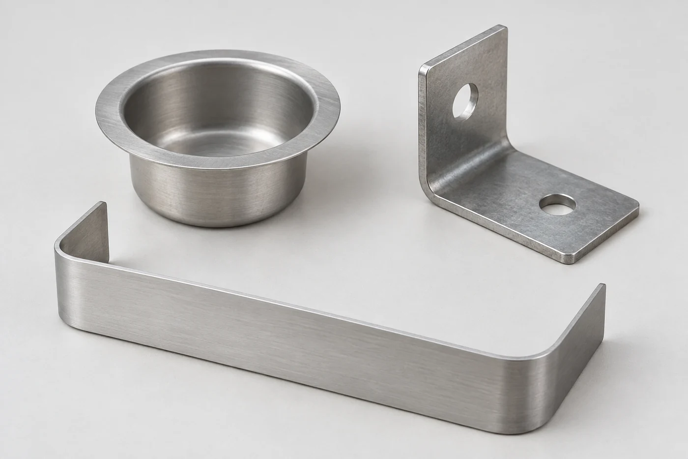
페라이트계 SUS430은 오스테나이트계 304와 다른 결정 구조를 가진 스테인리스입니다. 자성이 있고 비교적 온화한 부식 환경의 부품에 쓰일 수 있지만, 이 특성만으로 304를 대체할 수는 없습니다. 성형 경로와 용접, 노출 환경을 다시 검토해야 합니다. 안정화 원소를 포함한 다른 페라이트계 제품의 성능을 일반 430에 그대로 적용해서도 안 됩니다.
| 재료군 | 강화·사용의 특징 | 확인할 점 |
|---|---|---|
| SUS430 계열 | 페라이트계 내식 판재, 자성 | 방향성·성형 표면·용접과 부식 환경 |
| 탄소 스프링·공구강 판재 | 성분과 열처리 상태에 따른 높은 경도·강도 | 성형 전후 상태, 담금질·뜨임, 탈탄·뒤틀림 |
| 경화·뜨임 완료 스트립 | 최종 기계적 성질을 가진 상태로 공급 | 제한된 굽힘성·절단 가공성·후속 열 영향 |
탄소 스프링강은 부품 형상을 만든 뒤 담금질과 뜨임으로 필요한 상태를 얻는 경로가 있습니다. 성형 전에 이미 경화된 스트립을 쓰는 경로와는 공정의 자유도가 다릅니다. 담금질만으로 최대 경도를 얻는 것이 목적이 아니라, 요구 탄성 하중과 파손 위험을 고려한 최종 상태를 만드는 것이 목적입니다.
도면에 SK5처럼 과거에 사용되던 표기가 있으면 현재 구매 규격과 제조사 자료에서 기호·성분·공급 상태를 확인합니다. 비슷한 탄소 함량이나 관행적 대응표만으로 SK85 등 다른 표기와 자동 동등 승인하지 않습니다. 판재와 스트립, 소둔재와 경화재를 구분해 재료 성적서까지 연결해야 합니다.
| 열처리 관련 변수 | 완성품 영향 |
|---|---|
| 산화·탈탄 | 표면 상태와 표면 강도의 변화 |
| 냉각·지지 조건 | 뒤틀림과 치수 변화 |
| 뜨임 상태 | 최종 경도·강도와 파손 거동 |
| 후속 도금·접합 | 수소·열 이력과 표면 및 하중 특성 |
높은 경도는 좋은 스프링의 충분조건이 아닙니다. 타발 가장자리의 결함, 굽힘부의 미세 균열, 부식 흔적이 반복 하중의 시작점이 될 수 있습니다. 필요하면 열처리 전후 치수와 경도 분포, 탈탄층, 부품 하중-변위와 반복 성능을 연결해 판정합니다. 얇은 탄소강 부품의 부식 보호도 최종 사용 조건의 일부입니다.
R/t = 안쪽 굽힘 반지름 ÷ 판 두께
이 모델은 같은 두께의 판을 90°로 연결한 이상적인 굽힘 형상입니다. RD는 평판의 압연 방향이고 굽힘 축은 곡면 중심을 지나는 선입니다. 버튼으로 두 방향의 관계를 바꾸고 R/t를 비교할 수 있습니다. 압연 방향 표시는 시편 표면을 읽기 위한 표식이며 실제 홈이 아닙니다. 방향·R/t만으로 균열 유무를 판정하지 않습니다. 최소 굽힘 반지름은 합금·조질·판 두께·버 방향·가공 조건과 공급사 기준을 함께 확인해야 합니다. 두께 감소·중립축 이동·스프링백·전개 길이는 이 형상 모델에 포함되지 않습니다.
순동은 전류와 열을 전달하는 판재를 검토할 때 출발점이 됩니다. C1100 계열의 터프피치동과 C1020 계열의 무산소동은 모두 높은 전도성을 가지지만 산소 상태가 다릅니다. 따라서 구리 함량만으로 고르지 않고 후속 용접·브레이징의 분위기와 열 이력을 함께 확인합니다. 산소를 포함한 동은 특정 고온 수소 분위기에서 내부 산화물과 수소의 반응으로 손상될 수 있습니다.
전기 전도성이 좋다는 이유만으로 순동을 탄성 접촉편에 바로 적용해서는 안 됩니다. 연질 순동은 성형하기 쉽지만 영구 변형이 생기기 쉬운 하중 범위가 있습니다. 냉간 가공으로 강도를 높여도 이후 열이 가해지면 연화될 수 있습니다. 넓은 통전 단면이 필요한 연결판과 반복 처짐을 받는 스프링은 서로 다른 선정 기준을 가집니다.
| 재료군 | 주요 특성 | 공정·사용 시 검토 |
|---|---|---|
| 터프피치동 C1100 계열 | 높은 전도성·열전도성, 우수한 연질 성형성 | 산소 상태, 접합 열 이력, 변형 유지 |
| 무산소동 C1020 계열 | 높은 전도성과 산소 관련 접합 문제의 감소 | 요구 순도·공급 규격·최종 조질 |
| 황동 C2600 계열 | Cu-Zn 합금의 성형성과 가공경화 | 연질 드로잉과 경질 접촉편의 구분 |
| 황동 C2680 계열 | C2600보다 아연 비율이 높은 별도 조성군 | 요구 물성·조질·환경에 맞춘 별도 검증 |
황동은 구리에 아연을 더한 합금입니다. C2600과 C2680을 색상 차이 정도로 취급하면 안 됩니다. 같은 공급표 안에서도 연질 O와 H·EH 등은 인장강도와 연신율의 조합이 다릅니다. 타발과 굽힘을 수행한 뒤 남는 강도, 접촉 하중과 균열 여부를 봐야 하며, 구리와 같은 두께라는 이유로 같은 전류 용량을 적용할 수 없습니다.
| 공개 참고값의 예 | 전도율 | 비교의 범위 |
|---|---|---|
| 순동 C1100·무산소동 제품 | 약 101% IACS | 제조사 대표값, 293 K 기준 |
| C2600 황동 제품 | 약 28% IACS | 제조사 참고값 |
| C2680 황동 제품 | 약 27% IACS | 제조사 참고값 |
100% IACS는 모든 금속의 상한이 아니라 20°C의 표준 소둔 구리를 기준으로 정한 전도율 척도입니다. 따라서 100%를 넘는 값도 가능합니다. 이 비교는 전기저항의 재료적 차이를 보여주지만 완성품의 정격전류를 정하지는 않습니다. 실제 발열에는 길이·단면적·접속부 저항·방열 조건이 함께 들어갑니다. 황동은 잔류 인장응력과 특정 부식 환경이 겹칠 때 응력부식균열도 검토해야 합니다.
인청동은 구리-주석-인 계열의 합금이며, 프레스 접촉편에서는 성형 뒤 필요한 탄성 기능을 얻는 데 활용됩니다. C5191과 스프링용 C5210은 같은 이름으로 묶이는 인청동이지만 성분 범위와 제품 규격, 공급 조질이 다릅니다. 숫자가 큰 쪽을 무조건 상위 재료로 보는 대신 굽힘 형상과 사용 하중을 기준으로 비교해야 합니다.
냉간 압연으로 강도를 높이면 프레스 후 탄성 하중을 확보하는 데 유리할 수 있지만, 좁은 굽힘부에 허용되는 소성 변형은 줄어들 수 있습니다. 같은 인장강도에서도 결정립과 집합조직, 가공 이력에 따라 굽힘성이 달라집니다. 인청동의 미세조직을 제어한 연구에서는 강도와 굽힘성의 조합을 개선할 수 있음을 보여주지만, 그 결과를 모든 일반 인청동에 그대로 적용할 수는 없습니다.
| 공급 상태의 예 | 인장강도 Rm | 0.2% 내력 | 적용 두께 |
|---|---|---|---|
| C5210-H | 590–705 MPa | 450 MPa 이상 | 0.10–1.60 mm |
| C5210-EH | 685–785 MPa | 580 MPa 이상 | 0.10–1.20 mm |
| C5210-SH | 735–835 MPa | 640 MPa 이상 | 0.10–1.20 mm |
위 표는 한 제조사가 공개한 스프링용 스트립 표의 일부입니다. 해당 표의 조질·두께 범위에 한정되며 다른 공급자의 보증값을 대신하지 않습니다. 성적서에서는 인장 방향과 연신율의 표점거리까지 확인합니다. 같은 H 표기라도 다른 합금의 H와 같은 강도라는 의미는 아닙니다.
| 판단 항목 | 인청동에서 연결할 내용 |
|---|---|
| 굽힘성 | 조질·판 두께·굽힘축 방향·모서리 상태 |
| 통전 | 순동보다 낮은 전도율과 실제 전류 경로 |
| 하중 유지 | 초기 하중과 고온 유지 뒤의 잔류 하중 |
| 피로 | 반복 변위·평균 응력·타발면·굽힘부의 집중 응력 |
인청동의 전도율은 합금과 제품에 따라 다릅니다. 대표 공개값에서는 C5191이 약 14% IACS, C5210이 약 12% IACS로 제시되지만 이를 온도·상태와 무관한 상수로 사용하지 않습니다. 특히 접촉편의 온도가 올라가면 전기저항 증가와 응력 완화가 함께 문제될 수 있습니다. 지정 온도·변위·시간에서 하중이 얼마나 남는지 측정하고, 반복 작동 시험은 별도로 수행해야 합니다.
CuNiSi 계열은 구리 안에 니켈과 규소를 포함한 미세 석출물을 형성해 강도와 전도성의 조합을 얻습니다. C7025라는 제품명이 널리 쓰이지만 공급표에는 UNS C70250, 적용 규격과 제조사 고유 조질이 함께 등장합니다. 따라서 명칭만으로 다른 업체의 TM·TR 상태를 서로 바꾸어 쓰지 않습니다.
| 구분 | 강화·공급의 특징 | 프레스에서 확인할 내용 |
|---|---|---|
| CuNiSi 계열 | 석출 제어와 냉간 가공의 조합 | 조질별 강도·전도율·굽힘성·응력 완화 |
| 시효경화형 베릴륨동 | 성형 가능한 상태로 공급 후 지정 시효 | 성형 순서, 시효 후 수축·변형·최종 물성 |
| 밀하든형 베릴륨동 | 제조사가 경화 상태를 조정해 공급 | 공급 상태의 성형 한계와 후속 열 이력 |
C7025 커넥터용 공개 데이터의 한 예에서 TM00의 0.2% 내력은 450–620 MPa, TM03은 655–830 MPa이며, 두 상태의 전도율 대표값은 모두 45% IACS입니다. 이는 조질 변화가 물성을 같은 비율로 움직이지 않는다는 좋은 예입니다. 공급표가 제시하지 않은 시험 방향이나 두께 조건까지 추정해서 보증 범위를 넓히지 않아야 합니다.
베릴륨동 C17200 계열은 성형 후 시효경화로 높은 강도를 얻는 경로와, 미리 경화된 스트립을 사용하는 경로를 구분합니다. 전자는 최종 경화 전에 복잡한 형상을 만들 수 있지만 시효 후 치수·뒤틀림을 확인해야 합니다. 후자는 별도 시효를 생략할 수 있는 공급 상태가 있으나, 이미 확보된 강도만큼 굽힘 여유를 면밀히 검토해야 합니다.
| 동합금 선택의 질문 | 판단에 필요한 자료 |
|---|---|
| 높은 초기 하중이 필요한가? | 최종 상태의 내력·형상·허용 변위 |
| 고온에서도 하중을 유지해야 하는가? | 같은 초기 응력 비율·온도·시간의 응력 완화 곡선 |
| 통전 발열을 줄여야 하는가? | 최종 조질의 전도율과 접합부 저항 |
| 작은 반경으로 굽혀야 하는가? | 두께·방향·시험 형상이 명시된 굽힘 데이터 |
어느 합금이 더 오래 버틴다는 결론은 상온 인장강도 순위로 정하지 않습니다. 한쪽은 초기 응력이 항복 기준에 더 가깝거나 시험 온도가 다를 수 있기 때문입니다. 베릴륨동은 물성뿐 아니라 가공 형태에 맞는 취급 조건도 포함해야 합니다. 특히 연마·절삭 등 분진이 생기는 공정은 해당 재료의 안전자료와 작업 관리 조건을 적용합니다.
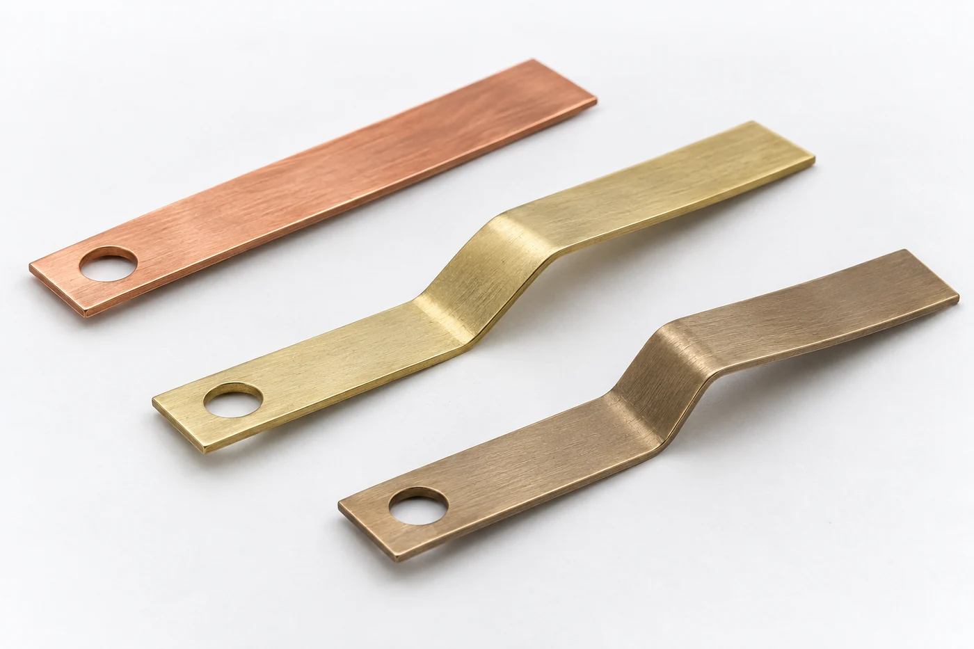
알루미늄은 가벼운 판재를 만들 수 있지만, 같은 형상의 강판을 단순히 알루미늄으로 바꾸면 처짐이 커질 수 있습니다. 강성은 밀도나 인장강도 하나로 결정되지 않습니다. 두께·단면 형상과 탄성계수를 함께 검토해야 하며, 나사·리벳 등 체결부의 국부 변형도 확인해야 합니다.
| 합금군 | 주요 특징 | 프레스 적용의 관점 |
|---|---|---|
| 1050 | 높은 알루미늄 순도, 우수한 성형성, 비교적 낮은 강도 | 깊은 성형·열 전달과 형상 유지의 균형 |
| 3003 | Mn을 포함한 비열처리형 합금 | 성형성·강도·내식성을 함께 보는 커버·드로잉품 |
| 5052 | Mg를 포함한 비열처리형 합금 | 더 높은 강도 요구와 굽힘성·내식성의 조합 |
이 재료군의 O는 소둔 상태, H 계열은 가공경화와 추가 처리 상태를 나타냅니다. 예를 들어 H14와 H32는 마지막 숫자만 다른 동일 공정이 아닙니다. H1 계열은 가공경화, H3 계열은 가공경화 뒤 안정화 처리와 연결됩니다. 따라서 5052-H32의 성질을 5052-O나 H34에 그대로 적용하지 않습니다.
| 제조사 판재 데이터 예 | 0.2% 내력 | 인장강도 | 연신율 A50 |
|---|---|---|---|
| 1050-O, 0.5<t≤1.5 mm | 20 MPa 이상 | 65–95 MPa | 22% 이상 |
| 1050-H14, 0.5<t≤1.5 mm | 85 MPa 이상 | 105–145 MPa | 2% 이상 |
위 표는 동일한 두께 구간의 공급사 공개값을 비교한 예입니다. 시험 방향과 온도는 해당 요약표에 명시되지 않으므로 별도 협의가 필요합니다. H14의 높은 내력은 영구 변형을 억제하는 데 도움이 되지만, O 상태에서 가능했던 성형을 그대로 수행할 수 있다는 뜻은 아닙니다. A50도 표점거리 50 mm의 연신율이며 다른 시편의 연신율과 숫자만 비교하지 않습니다.
알루미늄의 자연 산화피막은 내식성에 기여하지만 전기 접촉면과 접합에서는 별도로 다루어야 합니다. 또 연질 표면의 긁힘과 공구 소착은 외관만의 문제가 아닙니다. 깊은 흠이나 끌림이 변형을 집중시킬 수 있으므로 윤활·공구면·보호필름과 최종 세정의 조합을 정합니다. 양극산화나 도장 뒤 체결·접지 기능도 완성 상태에서 검토합니다.
6xxx계 알루미늄은 Mg와 Si를 이용한 석출경화로 필요한 물성을 얻는 열처리형 합금군입니다. 프레스 재료로 검토할 때 6061이라는 합금명만 적으면 충분하지 않습니다. O·T4·T6처럼 상태가 달라지면 성형 가능 범위와 최종 강도가 달라지며, 성형 이후 열처리를 할 것인지까지 공정에 포함해야 합니다.
| 상태 | 기본 의미 | 프레스 검토 |
|---|---|---|
| O | 소둔 상태 | 성형 여유와 이후 필요한 최종 상태 |
| T4 | 용체화 처리 후 자연시효 | 성형 시점·보관 이력·후속 시효 계획 |
| T6 | 용체화 처리 후 인공시효 | 높은 강도 상태에서의 제한된 굽힘 여유 |
6061의 공개 제품 자료는 O와 T4를 상대적으로 성형에 유리한 상태로, T6를 더 제한적인 냉간 가공 상태로 구분합니다. 하지만 이것은 특정 반경이면 반드시 합격한다는 뜻이 아닙니다. 판 두께, 압연 방향, 공구 반경, 가장자리 품질과 성형 경로가 함께 맞아야 합니다. 특히 다른 제품 형태의 인장시험 수치를 얇은 판재의 굽힘 보증값으로 바꾸지 않습니다.
성형하기 쉬운 상태에서 형상을 만든 뒤 최종 물성을 얻는 경로를 택하면, 열처리 중 변형과 치수 변화를 함께 관리해야 합니다. 이미 T6인 판재를 억지로 작은 반경에 굽히는 것과는 다른 문제입니다. 이때 열처리 온도·시간을 임의로 일반화하지 말고, 해당 합금·두께·목표 상태에 맞는 승인 공정을 적용합니다.
| 설계·공정 질문 | 확인할 결과 |
|---|---|
| 성형 후 열처리하는가? | 치수·평탄도·최종 강도와 표면 |
| 용접하는가? | 열영향부의 국부 물성·변형·접합 성능 |
| 얇은 부품에 체결하는가? | 접촉면 압흔·국부 변형·반복 풀림 |
| 전류를 흘리는가? | 조질별 전도율·표면피막·접합부 저항 |
고강도 6xxx계를 쓴다고 얇은 판의 탄성 처짐이 자동으로 작아지지는 않습니다. 같은 형상이라면 강성과 항복에 대한 역할을 나누어 판단해야 합니다. 용접 열을 받은 부분도 모재의 T6 성적서 값이 그대로 유지된다고 가정하지 않습니다. 설계가 요구하는 상태는 입고 재료의 상태가 아니라 모든 성형·접합·열처리가 끝난 상태입니다.
재료 특성은 금형 조건과 만나 최종 형상으로 나타납니다. 타발에서는 두께·전단 저항·연성과 날의 상태가 절단면과 버에 영향을 줍니다. 절곡에서는 항복 수준·가공경화·탄성계수·R/t와 방향이 복원량과 균열에 연결됩니다. 드로잉에서는 재료 유입, 마찰, 블랭크 홀더 하중과 두께 변형을 함께 보아야 합니다.
| 공정 | 주요 재료 변수 | 확인할 결과 |
|---|---|---|
| 타발·피어싱 | 두께, 강도, 연성, 표면층 | 버 높이·방향, 파단면, 미세 균열 |
| 굽힘·성형 | 조질, R/t, 압연 방향, 가장자리 | 각도·내측 반경, 외측 균열, 스프링백 |
| 드로잉 | n·r, 마찰, 결정립, 표면 | 최소 두께, 주름, 이어링, 표면 흠 |
| 접합·후처리 | 열·화학 노출, 코팅, 잔류 응력 | 연화·변형, 도금 밀착, 최종 하중 |
R/t는 내측 굽힘 반경 R을 판 두께 t로 나눈 값입니다. 같은 R이라도 판이 두꺼워지면 R/t가 작아져 외측 변형 요구가 커집니다. 다만 R/t 하나로 합격을 정하지는 않습니다. 굽힘축이 압연 방향과 평행인지 수직인지 명확히 쓰고, 타발 버가 놓이는 면과 실제 굽힘 시험 형상을 맞춥니다. 자료의 good way·bad way도 정의 그림을 확인해야 합니다.
윤활은 성형 중 마찰과 표면 손상을 줄이는 역할을 하지만, 남은 가공유가 도금·용접·납땜에 영향을 줄 수 있습니다. 금형 소착이 보이면 압력이나 윤활량 하나만 바꾸지 말고 공구면, 표면 거칠기, 소재 코팅, 세정성까지 원인 경로를 살핍니다. 소재가 바뀌면 기존의 클리어런스·윤활·성형 순서를 자동으로 유지하지 않습니다.
구속이 없는 균일한 부품의 작은 온도 변화는 ΔL ≈ α·L·ΔT로 길이 변화를 살펴볼 수 있습니다. 예를 들어 계산용 α=17×10⁻⁶/K, 길이 100 mm, 온도 상승 50 K를 놓으면 늘어나는 길이는 0.085 mm입니다. 이는 설명용 가정이며 특정 재료의 보증값이 아닙니다. 서로 다른 재료를 체결하면 자유 팽창 차이가 간극 변화나 내부 하중으로 이어질 수 있습니다.
| 현상 | 구분해야 하는 의미 |
|---|---|
| 열팽창 | 온도 변화에 따른 치수 변화 |
| 응력 완화 | 변위를 유지하는 동안 시간에 따라 응력이 감소 |
| 크리프 | 하중을 유지하는 동안 시간에 따라 변형이 증가 |
| 열처리 연화·시효 | 조직 변화로 최종 물성이 달라지는 과정 |
열팽창 3D는 자유 길이 변화만 보여줍니다. 완전히 고정된 부품의 응력, 온도 구배에 의한 휨, 접촉 미끄럼이나 항복을 계산하지 않습니다. 따라서 조립체 검토에서는 실제 고정 위치와 온도 분포를 정하고, 열사이클 전후의 간극·접촉 하중·영구 변형을 측정합니다.
ΔL = αL₀ΔT · L = L₀ + ΔL
기준 길이 100 mm의 판재가 외부 구속 없이 균일하게 가열되는 자유 열팽창 예제입니다. 두 시편의 왼쪽 끝을 비교 기준으로 나란히 놓았으며, 고정 지그로 묶은 상태가 아닙니다. 기준 시편과 팽창 시편의 차이를 보이기 위해 길이 변화만 40배 확대합니다. 표시 수치는 확대 전 계산값입니다. α는 이 온도 구간에서 일정하다고 가정한 예제 입력값이며, 특정 강종의 보증값이 아닙니다. 실제 부품에는 온도 구배·조립 구속·재료별 온도 의존성이 작용할 수 있습니다. 열응력·접촉 하중·열전도율은 이 화면에서 계산하지 않습니다.
선정의 출발점은 합금 이름이 아니라 부품이 해야 하는 일입니다. 형상을 유지하는 지지판인지, 반복해서 휘는 스프링인지, 전류를 전달하는 단자인지 먼저 정합니다. 그다음 성형량, 온도, 부식 환경, 접합과 표면처리를 연결합니다. 기능이 겹치는 부품은 가장 까다로운 한 가지 물성만 높이는 것으로 해결되지 않습니다.
| 주된 기능 | 먼저 확인할 재료 특성 | 완성품으로 검증할 항목 |
|---|---|---|
| 고정·지지 | 내력, 탄성계수, 내식성 | 처짐, 영구 변형, 조립 위치 |
| 깊은 성형 | 조질, 연신율, n·r, 표면 | 최소 두께, 균열·주름·이어링 |
| 탄성 유지 | 내력, 굽힘성, 응력 완화·피로 | 하중-변위, 잔류 하중, 반복 수명 |
| 통전 | 전도율, 온도 특성, 접합성 | 저항, 발열, 접합·접촉 안정성 |
| 경량 외장 | 밀도, 강성, 성형성, 표면 | 패널 처짐, 체결부, 표면 내구성 |
입고 때는 재질 성적서와 코일·로트의 연결을 확인합니다. 합금 성분이 맞아도 조질·두께 분포·폭·캠버·평탄도가 달라지면 이송과 성형이 달라질 수 있습니다. 얇은 스트립에서는 두께 측정의 접촉력과 측정 위치를 정해 압흔이나 가장자리 영향을 줄입니다. 경도는 유용한 선별값이지만 인장·굽힘·응력 완화 성능을 모두 대신하지 않습니다.
| 도면·발주서 항목 | 명시할 내용 |
|---|---|
| 재료 정의 | 적용 규격·판본, 재질, 제품 형태, 조질 |
| 기하 조건 | 소재 두께·공차, 압연 방향, 버 허용 방향 |
| 표면·후처리 | 표면 상태, 코팅/도금, 세정, 열처리 순서 |
| 성능·검사 | 하중-변위, 온도·시간·횟수, 측정 지그와 판정 기준 |
| 변경 관리 | 제조사·조질·공정 변경 시 재검증 범위 |
시제품에서는 소재 성적서와 실제 부품 결과를 연결해 기록합니다. 굽힘 각도만 맞추는 데서 끝내지 않고 타발 가장자리의 균열, 성형부의 최소 두께, 조립 후 하중을 함께 봅니다. 전기 접촉편은 최종 도금과 열 이력을 거친 뒤 저항·발열·하중 유지 특성을 평가해야 합니다. 재질을 바꿀 때도 기존 재료와 같은 형상·지그·시험 조건으로 비교해야 원인을 분리할 수 있습니다.
아이디메탈의 프레스·전기접점 제작 검토에서는 부품 도면에 재질과 조질, 사용 온도, 통전 여부, 반복 작동 조건을 함께 제시하는 것이 출발점입니다. 이 자료가 있어야 성형 가능성과 완성품 기능을 같은 기준으로 논의할 수 있습니다. 소재명 하나를 바꾸는 결정보다, 필요한 성질을 공급 상태와 제조 공정 끝까지 유지하는 설계가 중요합니다.
Stamping materials must form successfully inside the die and retain the required geometry and function after leaving it. Even at the same thickness, changes in alloy, temper or rolling direction can alter bend cracking, springback, contact force and electrical behavior.
This guide examines cold-rolled steel, stainless steel, copper, brass, phosphor bronze, advanced copper alloys and aluminum. It connects material data with stamping processes, then explains how to specify the grade, condition and inspection around the function of the finished part.
Material behavior
Separate stiffness, strength, ductility and conductivity.
Grade and condition
Compare alloy, temper, thickness and direction together.
Process and finished part
Connect forming, retained force, surfaces and inspection.
The first distinction is between resistance to elastic deflection and the onset of permanent deformation. Elastic modulus E describes the elastic response. Yield strength or 0.2% proof stress provides a criterion for permanent deformation. Tensile strength Rm is the maximum engineering stress in a tensile test, not an allowable continuous service stress.
Changing a soft temper to a harder temper of the same alloy can substantially alter proof stress and forming capacity. The elastic modulus does not rise in the same proportion. To change spring stiffness, review thickness, width, effective length and support conditions as well as temper.
| Property | Meaning | Conditions to establish |
|---|---|---|
| E, elastic modulus | Elastic slope and deflection | Temperature, direction, geometry and supports |
| Rp0.2 / yield strength | Specified permanent strain or yielding | Proof stress versus upper/lower yield point |
| Rm, tensile strength | Maximum engineering tensile stress | Temper, thickness and sampling direction |
| A, elongation | Extension after fracture | Gauge length, specimen and direction |
| n / r | Strain-hardening exponent / plastic strain ratio | Strain interval, direction and test method |
| Conductivity / expansion coefficient | Conduction loss / thermal length change | Temperature, temper and temperature interval |
The n-value describes work hardening during plastic deformation. Work hardening can distribute strain and delay localization, while also raising the flow stress needed in later forming. The r-value relates width and thickness plastic strains and helps assess resistance to thinning in deep drawing. Elongation alone cannot represent bending, drawing and hole-expansion capability: each operation concentrates strain in a different way.
Numerical examples retain the conditions stated in the relevant public material data. Standard requirements, supplier reference values and calculation assumptions are different categories. Similar grade names do not establish equivalence when chemistry, product form, temper or testing differs. Specify the governing standard and edition rather than replacing JIS, KS, EN or ASTM designations through a simple lookup table.
The interactive elastic model varies E, thickness and load for a simple cantilever. It does not calculate large deflection, contact, plasticity, residual stress or fatigue in a real clip. The photographs are generated editorial illustrations of materials and geometry, not documentary photographs of actual deliveries or test results.
I = bt³/12 · k = 3EI/L³ · δ = F/k
The example assumes a rectangular cantilever with length L=30 mm, width b=12 mm and a concentrated end load. Changing E, thickness or load recalculates stiffness, deflection and nominal stress using linear elastic beam theory. Only displacement is enlarged 5×; sheet thickness is not enlarged. Inputs are independent hypothetical values, not comparative grade data. Materials with the same E can have different yield strength, 0.2% proof stress and fatigue life. Small deflections, a uniform section and ideal fixation are assumed. Shear deformation, residual stress, stress concentrations and plasticity are not calculated. Whether the inputs remain within a real material’s elastic range requires separate verification.
Cold-rolled steel is considered for brackets, covers, support plates and drawn parts. SPCC, SPCD and SPCE are not a ladder of progressively higher strength. They distinguish commercial, drawing and deep-drawing purposes. More demanding drawing calls for attention to thickness strain and rolling texture as well as ductility.
| Classification | Focus | Common selection pitfall |
|---|---|---|
| SPCC-family commercial quality | General-purpose cold-rolled sheet | The name alone does not guarantee every tensile property |
| SPCD-family drawing quality | Quality intended for drawing | Forming response may differ from commercial sheet at equal thickness |
| SPCE-family deep-drawing quality | More demanding material inflow and forming | Final geometry, n/r and thickness distribution still matter |
| Temper and surface symbols | Temper rolling and finish | Specify separately from the grade |
A lower yielding level and suitable work hardening can assist forming. The finished support, however, must resist permanent deformation under its required load. Evaluate formability together with the means of making the part function structurally. Section depth, ribs and bend placement can increase stiffness, provided the process and assembly envelope accommodate them.
Yield-point elongation in thin steel can produce stretcher-strain markings after forming. Temper rolling and aging condition are therefore relevant to appearance. For visible surfaces, assess storage history and the formed surface as well as the incoming finish. A commercial-quality designation alone does not establish identical surface stability.
| Forming issue | What to examine with the material |
|---|---|
| Thinning or failure in a deep cup | Drawing quality, r/n, inflow resistance and tool radii |
| Uneven rim height | Planar anisotropy and blank orientation |
| Wrinkling in a wide region | Thickness, inflow and holder conditions |
| Rust on finished parts | Finishing, cut edges, cleaning and storage |
Plain carbon steel should not be treated as providing the corrosion behavior of stainless steel. Define the finished coating, paint or protective oil, and assess how fasteners and cut edges are protected in service. This is why formability, strength and surface protection are separate requirements in stamping-stock selection.
Coated steel combines a substrate with additional surface materials and functions. Electrogalvanized, hot-dip galvanized and galvannealed sheet do not share the same coating route or surface behavior. SECC is not a generic name for every zinc-coated sheet. Specify the substrate’s forming grade together with coating type, mass and treatment.
| Layer or item | Function | Check after stamping |
|---|---|---|
| Substrate | Strength, formability and support | Blanking, bending and drawing results |
| Metallic coating | Corrosion protection and surface response | Flaking, powdering, scratches and cut edges |
| Conversion or organic treatment | Protection, lubrication or paint adhesion | Compatibility with grounding, joining and cleaning |
| Finished surface | Actual assembly and environment interface | Contact resistance, corrosion and appearance |
A structurally adequate substrate can still have a surface film that interferes with grounding. A conductive surface, in turn, does not eliminate coating damage or corrosion at formed regions. For electrical functions, define the contact-area finish and fastening arrangement, then measure resistance on the finished assembly.
High-strength low-alloy and multiphase steels use different strengthening mechanisms. At similar tensile strength, yield ratio, work hardening, hole expansion and edge-cracking behavior can differ. For a pierced-and-flanged hole, local formability of the cut edge can be more directly relevant than total tensile elongation.
| Geometry requirement | Additional verification |
|---|---|
| Tight bend | Bend testing, outer cracks and springback |
| Hole flanging | Cut-edge quality and hole-expansion capability |
| Long thin walls | Sidewall curl, twist and residual stress |
| Cyclic support | Fatigue at cut edges/bends and loading history |
Higher strength does not proportionally raise elastic modulus, so small elastic deflection does not automatically decrease at unchanged geometry. The load at which permanent deformation begins can change. Fatigue also depends on surfaces, cut edges, stress concentration and mean stress. “High-strength steel” alone does not establish superiority under every cyclic condition.
Austenitic stainless steels are frequently considered where corrosion resistance and formability are both required. SUS301, SUS304 and SUS316L are not interchangeable sheets. Hard spring strip and annealed stock can have very different yielding and bending behavior within the same family. The supplied condition must be read alongside the grade.
| Grade family | Main character | Stamping review |
|---|---|---|
| SUS301 family | Substantial cold-work strengthening | Final spring temper and remaining bend capacity |
| SUS304 family | Balanced general corrosion resistance, forming and joining | Work hardening, pickup and later welding |
| SUS316L family | Molybdenum-bearing corrosion design with low carbon | Actual environment, thermal history and formability |
The 301 family is used for spring strip strengthened by cold rolling. The 304 family covers a broad range of uses, but hardening during forming can alter the load and fracture conditions in later operations. Molybdenum-bearing corrosion behavior is an important reason to consider 316L. It does not imply immunity in every salt, acid or hot environment.
Surface designations such as 2B and BA do not identify a hard spring condition. Brightness and smoothness do not reveal final proof stress or cyclic life. The low carbon in 304L and 316L is relevant to sensitization associated with welding heat; it is not a statement that every mechanical property is identical to 304 or 316.
| Observation | Interpretation |
|---|---|
| Magnetism after cold forming | Possible deformation-induced structural change; a magnet cannot identify the grade |
| Angle changes after unloading | Elastic recovery depends on history and geometry |
| Material pickup on the tool | Review friction, finish, lubrication and tooling together |
| Properties change after welding | Verify the heat-affected region, corrosion behavior and geometry |
Conventional solution-treated austenitic stainless is essentially nonmagnetic, but cold work can change magnetic response. Weak attraction does not establish corrosion performance either. These grades are also not hardened through the ordinary quench-and-temper route used for carbon steels. Identify the strengthening mechanism before changing the material condition.
Inspect outer bends and sheared edges for cracking under magnification. Where assembly force matters, measure force-displacement on parts made in the actual rolling orientation. A photograph’s surface gloss does not certify a SUS grade or temper; appearance and function require separate checks.
Ferritic SUS430 has a different crystal structure from austenitic 304. It is magnetic and can suit relatively mild corrosive environments, but these facts do not establish interchangeability with 304. Revisit forming, welding and exposure. Do not transfer the performance of stabilized ferritic alternatives to ordinary 430.
| Family | Behavior and route | What to check |
|---|---|---|
| SUS430 family | Magnetic ferritic corrosion-resistant sheet | Directionality, formed surface, welding and exposure |
| Carbon spring/tool-steel sheet | Hardness and strength depend on chemistry and heat treatment | Pre/post-forming condition, quenching/tempering, decarburization and distortion |
| Hardened-and-tempered strip | Supplied with developed mechanical properties | Bend limitations, cutting and subsequent heat |
One carbon spring-steel route forms the part before quenching and tempering. This offers different manufacturing freedom from starting with hardened strip. The objective is not simply maximum as-quenched hardness. It is a final condition suited to the required elastic loading and fracture resistance.
If an older drawing uses a designation such as SK5, check the symbol, chemistry and supplied condition against the applicable purchasing specification and producer data. Similar carbon content or an informal cross-reference does not automatically approve another designation such as SK85. Distinguish sheet from strip and annealed from hardened material, and connect the selection to certification.
| Heat-treatment variable | Finished-part effect |
|---|---|
| Oxidation and decarburization | Changes in surface condition and strength |
| Cooling and support | Distortion and dimensional movement |
| Tempering condition | Final hardness/strength and fracture behavior |
| Later plating or joining | Hydrogen/thermal exposure and surface/force behavior |
High hardness alone does not make a satisfactory spring. Edge defects, bend microcracks and corrosion damage can initiate fatigue. Where required, evaluate pre/post-heat-treatment dimensions, hardness distribution, decarburization, force-displacement and cyclic behavior together. Corrosion protection remains part of the finished thin-steel component’s service requirements.
R/t = inside bend radius ÷ sheet thickness
This model shows an ideal 90° bend joining sheet of constant thickness. RD marks the rolling direction on the flat sheet; the bend axis passes through the centre of curvature. Toggle their relationship and compare R/t. The rolling-direction arrow is an explanatory overlay, not a physical groove. Direction and R/t alone do not predict cracking. Minimum bend radius requires alloy, temper, thickness, burr direction, process conditions and supplier guidance to be considered together. Thinning, neutral-axis shift, springback and blank development are not included in this geometric model.
Pure copper is a starting point for sheet parts that carry current and heat. Tough-pitch copper of the C1100 family and oxygen-free copper of the C1020 family both offer high conductivity, but differ in oxygen condition. Selection must include joining atmosphere and thermal history. In certain high-temperature hydrogen environments, reactions involving internal oxides can damage oxygen-bearing copper.
Good electrical conductivity alone does not qualify pure copper for a spring contact. Soft copper forms readily but has a limited load range before permanent set. Cold work raises strength, yet later heating can soften it. A current-carrying link and a repeatedly deflected spring therefore require different selection criteria.
| Family | Main behavior | Process and service review |
|---|---|---|
| C1100-family tough-pitch copper | High electrical/thermal conduction; good soft-temper forming | Oxygen condition, joining heat and permanent set |
| C1020-family oxygen-free copper | High conduction with reduced oxygen-related joining concerns | Purity, supply specification and final temper |
| C2600-family brass | Cu-Zn formability and work hardening | Separate soft drawing stock from hard spring stock |
| C2680-family brass | A distinct composition with more zinc than C2600 | Verify properties, temper and service environment |
Brass adds zinc to copper. C2600 and C2680 should not be treated as merely different colors. O, H and EH conditions have different strength/elongation combinations even within one supplier’s range. Evaluate strength, contact force and cracking after forming. Equal thickness to copper does not establish equal current capacity.
| Published reference example | Conductivity | Scope |
|---|---|---|
| C1100 / oxygen-free copper products | About 101% IACS | Supplier reference, 293 K |
| C2600 brass product | About 28% IACS | Supplier reference value |
| C2680 brass product | About 27% IACS | Supplier reference value |
One hundred percent IACS is a conductivity reference based on standard annealed copper at 20°C, not an absolute maximum. Values above 100% are therefore possible. These figures compare material resistance but do not establish a finished-part current rating. Heating also depends on length, section, joint resistance and cooling. For brass, residual tensile stress combined with particular corrosive environments can require stress-corrosion assessment.
Phosphor bronze is a copper-tin-phosphorus alloy family used for formed contact springs. C5191 and spring-grade C5210 belong to this family, but composition ranges, product specifications and available tempers differ. A larger grade number is not an automatic performance ranking. Compare the required bends and service loads.
Cold rolling can increase the strength available for elastic loading, while reducing the plastic strain that a tight bend can accommodate. Grain structure, texture and processing history can change bendability even at similar tensile strength. Research on controlled phosphor-bronze microstructures demonstrates improved strength/formability combinations, but those results do not automatically describe all conventional phosphor bronze.
| Example supplied condition | Tensile strength Rm | 0.2% proof stress | Thickness range |
|---|---|---|---|
| C5210-H | 590–705 MPa | At least 450 MPa | 0.10–1.60 mm |
| C5210-EH | 685–785 MPa | At least 580 MPa | 0.10–1.20 mm |
| C5210-SH | 735–835 MPa | At least 640 MPa | 0.10–1.20 mm |
The table reproduces selected numerical ranges from one producer’s spring-strip data. They apply only to the listed temper and thickness ranges and do not replace another supplier’s guarantee. Confirm tensile direction and elongation gauge length on the test documentation. H in another alloy does not mean the same strength.
| Decision | What to connect in phosphor bronze |
|---|---|
| Bendability | Temper, thickness, bend-axis direction and edge condition |
| Conduction | Lower conductivity than copper and the actual current path |
| Force retention | Initial force and force remaining after hot exposure |
| Fatigue | Cyclic displacement, mean stress, cut edge and bend concentration |
Conductivity varies with alloy and product. Published examples list about 14% IACS for C5191 and 12% for C5210; these are not condition-independent constants. A warmer contact spring may experience both increased resistance and stress relaxation. Measure retained force at a specified temperature, deflection and duration, and perform cyclic testing separately.
CuNiSi alloys use fine nickel-silicon-containing precipitates to obtain a strength/conductivity combination. The familiar C7025 product name may appear alongside UNS C70250, a governing specification and producer-specific tempers. Do not substitute one supplier’s TM or TR condition solely on the basis of a similar name.
| Type | Strengthening and supply | Stamping review |
|---|---|---|
| CuNiSi family | Precipitation control plus cold work | Temper-specific strength, conductivity, bending and relaxation |
| Age-hardenable beryllium copper | Formable supply followed by specified aging | Sequence, aging distortion and final properties |
| Mill-hardened beryllium copper | Producer supplies a controlled hardened condition | Forming limits in that condition and later heat exposure |
One published C7025 connector dataset gives 0.2% proof stress of 450–620 MPa for TM00 and 655–830 MPa for TM03, with 45% IACS as the typical conductivity of both. Changing temper therefore does not shift every property in the same proportion. Do not extend a guarantee by assuming unlisted thickness or test-direction conditions.
For the C17200 beryllium-copper family, distinguish forming followed by aging from using pre-hardened strip. The first route can form complex geometry before final hardening, but requires dimensional checks after aging. Some pre-hardened conditions avoid a separate aging operation, while requiring careful evaluation of the remaining bend capacity.
| Selection question | Evidence required |
|---|---|
| Is a high initial force needed? | Final proof stress, geometry and allowable displacement |
| Must force persist at temperature? | Relaxation curves at matched initial stress fraction, temperature and duration |
| Must electrical heating be reduced? | Final-temper conductivity and joint resistance |
| Are tight bends required? | Bending data with thickness, direction and test geometry |
Room-temperature tensile rankings do not establish which alloy will retain force longer. Initial stress may be closer to the proof limit in one test, or temperature may differ. Beryllium-copper selection also includes process-specific handling. Dust-generating operations such as grinding or machining require the material’s safety information and appropriate process controls.
Aluminum allows lightweight sheet parts, but simply replacing steel at unchanged geometry can increase deflection. Density or tensile strength alone does not determine stiffness. Review thickness, section geometry and elastic modulus, including local deformation at screws or rivets.
| Family | Main characteristics | Stamping perspective |
|---|---|---|
| 1050 | High aluminum content, good forming and relatively low strength | Balance deep forming/heat transfer with shape retention |
| 3003 | Manganese-bearing non-heat-treatable alloy | Formability, strength and corrosion behavior for covers/drawn parts |
| 5052 | Magnesium-bearing non-heat-treatable alloy | Combine greater strength demand with bending and corrosion behavior |
In these families, O denotes annealed material, while H tempers identify strain hardening and any associated treatment. H14 and H32 do not describe the same process with a different final digit. H1 relates to strain hardening; H3 includes stabilization after strain hardening. Properties for 5052-H32 should not be assigned to 5052-O or H34.
| Producer sheet-data example | 0.2% proof stress | Tensile strength | Elongation A50 |
|---|---|---|---|
| 1050-O, 0.5 < t ≤ 1.5 mm | At least 20 MPa | 65–95 MPa | At least 22% |
| 1050-H14, 0.5 < t ≤ 1.5 mm | At least 85 MPa | 105–145 MPa | At least 2% |
The example compares supplier data over the same thickness interval. Test direction and temperature are not stated in the summary table and require confirmation. H14’s higher proof stress helps resist permanent set, but does not preserve every forming operation possible in O. A50 is elongation over a 50 mm gauge length and should not be compared blindly with other specimen definitions.
Aluminum’s natural oxide contributes to corrosion resistance but needs separate consideration at electrical and joining interfaces. Scratching and tool pickup on soft surfaces are not merely cosmetic: deep marks can localize strain. Define lubrication, tooling, protective film and final cleaning together. Evaluate fastener and grounding functions after anodizing or painting.
The 6xxx aluminum family uses Mg-Si precipitation hardening to develop properties. “6061” alone is not a complete stamping-material specification. O, T4 and T6 conditions differ in forming capacity and strength. The process must also state whether heat treatment follows forming.
| Condition | Basic meaning | Stamping review |
|---|---|---|
| O | Annealed | Forming freedom and required final condition |
| T4 | Solution heat-treated and naturally aged | Timing, storage history and subsequent aging plan |
| T6 | Solution heat-treated and artificially aged | Reduced bend capacity in the higher-strength condition |
Published 6061 product data identifies O and T4 as more formable than T6 in cold working. This does not guarantee a pass at a particular radius. Thickness, rolling direction, tooling, edge quality and strain path must align. Tensile results from another product form are not a thin-sheet bend guarantee.
Forming in a more ductile condition and then developing final properties requires control of heat-treatment distortion and dimensions. This is a different problem from forcing an existing T6 sheet around a tight radius. Use an approved schedule for the alloy, thickness and target condition rather than a universal temperature/time recipe.
| Design or process question | Result to verify |
|---|---|
| Heat treatment after forming? | Dimensions, flatness, final strength and surface |
| Welding required? | Local heat-affected properties, distortion and joint behavior |
| Fastening through thin stock? | Indentation, local deformation and cyclic loosening |
| Current-carrying duty? | Temper-specific conductivity, oxide/finish and joint resistance |
A stronger 6xxx temper does not automatically reduce elastic deflection of a thin sheet. Separate stiffness from yielding at unchanged geometry. Nor should a welded region be assumed to retain the original T6 certificate properties. The relevant design condition is the state after all forming, joining and heat treatment.
Material behavior becomes finished geometry through the tooling conditions. In blanking, thickness, shear resistance, ductility and edge condition affect the cut face and burr. In bending, yielding, work hardening, E, R/t and direction influence recovery and cracking. Drawing also depends on material inflow, friction, blank-holder loading and thinning.
| Process | Material variables | Result to check |
|---|---|---|
| Blanking and piercing | Thickness, strength, ductility and coating | Burr height/direction, fracture face and microcracks |
| Bending and forming | Temper, R/t, rolling direction and edges | Angle/radius, outer cracks and springback |
| Drawing | n/r, friction, grain structure and surface | Minimum thickness, wrinkles, earing and surface marks |
| Joining and finishing | Heat/chemical exposure, coating and residual stress | Softening/distortion, adhesion and final force |
R/t divides the inside bend radius R by sheet thickness t. At a fixed radius, thicker stock has a smaller R/t and a greater outer-fiber deformation demand. R/t alone is not an acceptance rule. Specify whether the bend axis is parallel or perpendicular to rolling, identify the burr side, and match the test geometry. Verify the definitions behind “good way” and “bad way” in each source.
Lubrication controls friction and surface damage, but residues can affect plating, welding and soldering. When pickup occurs, investigate tool surfaces, roughness, coatings and cleaning as well as pressure or lubricant quantity. A material change does not automatically preserve the previous clearance, lubricant or forming sequence.
For a free, uniform part over a modest temperature interval, ΔL ≈ α·L·ΔT estimates length change. An illustrative α of 17×10⁻⁶/K, a 100 mm length and a 50 K rise give 0.085 mm expansion. These are calculation assumptions, not a guaranteed material value. Joining dissimilar materials can convert unequal free expansion into gap changes or internal loads.
| Phenomenon | Meaning to distinguish |
|---|---|
| Thermal expansion | Dimension changes with temperature |
| Stress relaxation | Stress decreases with time at maintained displacement |
| Creep | Strain increases with time under sustained load |
| Softening or aging | Microstructural changes alter the resulting properties |
The thermal model shows free length change only. It does not calculate stress under complete restraint, thermal-gradient bending, contact slip or yielding. Assembly review must define actual constraints and temperature distribution, then measure gaps, contact force and permanent set before and after thermal cycling.
ΔL = αL₀ΔT · L = L₀ + ΔL
This example assumes a 100 mm strip heated uniformly with no external restraint. The two left ends are aligned only as a comparison datum; they are not tied together by a fixture. Only the length change is enlarged 40× to distinguish the reference specimen from the expanded specimen. Readouts use the actual arithmetic scale. The assumed expansion coefficient is constant over the temperature interval and is not a guaranteed grade value. Real parts can have temperature gradients, assembly restraints and temperature-dependent properties. Thermal stress, contact load and thermal conductivity are not calculated here.
Start with the part’s job rather than an alloy name. Determine whether it holds a shape, repeatedly flexes or carries current. Then connect forming demand, temperature, corrosion environment, joining and finishing. A multifunctional part cannot be selected by maximizing only one property.
| Primary function | Material properties to review | Finished-part verification |
|---|---|---|
| Support and location | Proof stress, modulus and corrosion resistance | Deflection, permanent set and assembly position |
| Deep forming | Temper, elongation, n/r and surface | Minimum thickness, cracks, wrinkles and earing |
| Elastic retention | Proof stress, bendability, relaxation and fatigue | Force-displacement, retained force and cyclic life |
| Current conduction | Conductivity, temperature behavior and joining | Resistance, heating and interface stability |
| Lightweight enclosure | Density, stiffness, formability and surface | Panel deflection, fasteners and surface durability |
At incoming inspection, link the material certificate to the coil or lot. Correct chemistry does not prevent feeding or forming differences caused by temper, thickness distribution, width, camber or flatness. For thin strip, define measuring force and locations to limit indentation and edge effects. Hardness is a useful screening property, not a substitute for tensile, bending and relaxation performance.
| Drawing or purchase item | What to specify |
|---|---|
| Material definition | Standard/edition, grade, product form and temper |
| Geometry | Stock thickness/tolerance, rolling direction and permitted burr orientation |
| Surface and processing | Surface condition, coating/plating, cleaning and heat-treatment sequence |
| Performance and inspection | Force-displacement, temperature/time/cycles, fixture and acceptance criteria |
| Change control | Requalification after supplier, temper or process changes |
For prototypes, connect material records with actual part results. In addition to bend angle, inspect edge cracking, minimum formed thickness and assembled force. Electrical springs should be evaluated for resistance, heating and force retention after final plating and thermal processing. Compare material changes using matched geometry, fixtures and test conditions so that causes remain identifiable.
For an ID METAL stamping or electrical-contact review, provide the part drawing together with grade, temper, service temperature, current duty and cyclic requirements. These inputs allow formability and finished-part function to be discussed on the same basis. The central task is to preserve the required properties from supplied stock through the complete manufacturing sequence.
프레스 재료는 합금명뿐 아니라 조질·두께·압연 방향·표면과 최종 열 이력으로 정의합니다. 강판, 스테인리스, 동합금, 알루미늄의 강성·강도·연성·전도성을 구분하고, 성형 가능한 상태와 완성품이 기능하는 상태를 연결해야 합니다. 도면과 실제 부품 시험을 함께 사용해 선정과 변경을 승인합니다.
가능합니다. 조질, 두께 분포, 압연 방향, 표면 상태와 가공 이력이 다르면 성형 하중·균열·스프링백이 달라질 수 있습니다. 합금 성분만 아니라 공급 상태와 로트 기록을 비교해야 합니다.
반드시 그렇지는 않습니다. 탄성 범위의 처짐은 탄성계수와 형상·하중·지지 조건으로 결정됩니다. 높은 항복강도는 영구 변형이 시작되는 조건을 바꾸지만 탄성계수를 같은 비율로 높이지 않습니다.
이 명칭은 강도가 차례로 올라가는 순위가 아닙니다. 일반용과 드로잉용 등 성형 목적을 구분하고, 실제 강도와 연신율은 조질·두께·공급 규격과 성적서로 확인해야 합니다.
그 사실만으로 판정할 수 없습니다. 페라이트계는 자성을 가지며, 일부 오스테나이트계도 냉간 가공 뒤 자성이 나타날 수 있습니다. 재질 성적서와 적절한 성분·물성 확인으로 구분합니다.
통전 기능과 탄성 유지 기능을 함께 보아야 합니다. 순동의 전도성만으로 반복 처짐이나 고온 하중 유지를 판단할 수 없습니다. 인청동·CuNiSi·베릴륨동 등도 해당 조질의 강도·굽힘·응력 완화 조건으로 비교합니다.
5052는 가공경화·안정화 상태를, 6061은 용체화·시효 상태를 포함해 비교합니다. 성형량, 최종 강도, 용접과 표면처리, 열 이력에 따라 적합성이 달라지므로 합금명만으로 우열을 정하지 않습니다.
두께·조질·굽힘축 방향·시편 폭과 시험 형상이 일치하는지 먼저 확인해야 합니다. 타발면과 버, 공구 접촉 조건이 달라지면 실제 부품 결과도 달라질 수 있습니다.
기존·변경 재료의 규격과 조질, 성적서, 두께·방향·표면, 부품 도면, 성형·접합·열처리 순서와 사용 조건을 준비합니다. 같은 지그와 시험 조건에서 치수·하중·필요한 전기 및 내구 성능을 비교합니다.
강성은 하중을 받을 때 얼마나 변형되는지, 강도는 정해진 손상 또는 변형 기준을 언제 넘는지와 연결됩니다. 얇은 프레스품은 두께와 단면 형상도 함께 바꾸어 검토해야 합니다.
O·H·T 등은 공급 상태를 설명하고, 2B·BA나 코팅·도금 표기는 표면을 설명합니다. 외관이 비슷해도 내부 조직과 성형·탄성 기능은 다를 수 있습니다.
자유 열팽창, 구속에 따른 하중, 응력 완화와 크리프는 구분합니다. 온도와 시간이 작용한 뒤 실제 조립 상태의 간극·하중·저항을 확인해야 합니다.
제작 범위는 프레스 사업분야와 전기접점 사업분야에서 확인할 수 있습니다. 소재 검토는 동합금 스프링 소재, 가공과 형상은 금형 클리어런스와 절단 품질 및 프레스 브래킷의 내용과 연결됩니다.