
금속 브라켓 제작:
프레스 성형·보강 설계와 체결 품질관리
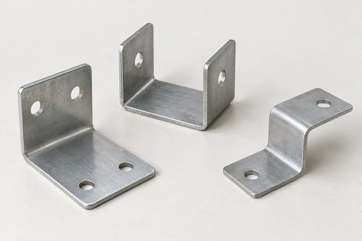
금속 브라켓 제작에서 작은 각도 오차나 체결면의 들뜸은 조립 위치와 하중 전달을 바꿉니다. 두께만 늘려도 해결되지 않는 이유는 굽힘부·보강 형상·볼트와 상대 구조물이 하나의 연결 구조로 움직이기 때문입니다. 형상 설계부터 프레스 공정과 최종 검사까지 같은 기능 기준으로 연결해야 합니다.
판재를 성형하는 일반 금속 브라켓을 중심으로 소재 선택, 전개와 홀 배치, 스프링백, 플랜지·비드 보강, 체결과 반복 하중을 살펴봅니다. 세 장의 사진형 일러스트와 세 가지 인터랙티브 3D는 이해를 돕는 개념 예시이며 실제 납품품이나 검증된 성능 데이터는 아닙니다.
형상과 하중 경로
L·U·Z 브라켓의 역할을 구분하고 소재·두께·보강 형상을 함께 정합니다.
프레스 공정과 형상 오차
전개·홀 배치·절단면·성형 순서와 스프링백을 연결합니다.
체결에서 최종 검증까지
기준면·장공·편심 하중·표면처리·검사와 발주 조건을 정리합니다.
01기능과 소재의 선택
브라켓의 기능과 하중 경로
금속 브라켓 제작에서 먼저 정할 것은 ㄱ자 모양이나 구멍 개수가 아닙니다. 무엇을 어느 위치에 지지하고, 어떤 방향의 힘을 어디로 전달할지부터 정해야 합니다. 같은 외형의 브라켓도 받침대, 위치 고정부, 간격 유지부 중 어떤 역할을 맡는지에 따라 중요한 면과 치수가 달라집니다.
하중은 장착 부품에서 브라켓의 접촉면으로 들어와 평판부·굽힘부·보강부를 지나 체결부와 상대 구조물로 나갑니다. 이 흐름에서 폭이 급격히 좁아지는 곳, 굽힘부 옆의 홀, 길게 돌출된 팔은 따로 살펴야 합니다. 볼트가 여러 개 있어도 브라켓의 휨과 접촉 상태 때문에 모든 볼트가 같은 힘을 받는다고 볼 수는 없습니다.
설치 조건에 따른 L·U·Z 형상
| 형상 | 구조적 쓰임 | 설계에서 함께 볼 항목 |
|---|---|---|
| L형 | 서로 다른 방향의 두 면을 연결 | 한쪽 팔의 휨·굽힘부 회전·볼트 접근 |
| U형 | 양쪽 벽으로 부품을 감싸거나 지지 | 벽 사이 간격·벌어짐·평행도·삽입 경로 |
| Z형 | 서로 평행하지만 높이가 다른 면 연결 | 오프셋 높이·편심 모멘트·두 굽힘의 누적 |
| 플랜지·보강형 | 단면 높이와 힘 전달 경로 보완 | 주변 간섭·국부 성형성·체결면 확보 |
예를 들어 돌출된 부품을 받치는 L형에서 하중 작용점이 고정면에서 멀어지면 같은 힘에도 더 큰 굽힘 모멘트가 생깁니다. 이때 재료를 바꾸기 전에 돌출 길이, 고정점 간격, 하중이 들어오는 위치를 검토하는 것이 유효합니다. 하중 경로를 짧게 만드는 변경은 부품 두께 증가와 다른 방식으로 문제를 해결합니다.
지지·위치 결정·체결의 구분
면으로 받치는 기능, 핀이나 기준 홀로 위치를 정하는 기능, 볼트로 눌러 고정하는 기능은 서로 구분합니다. 체결 홀만 크게 만들면 조립은 쉬워질 수 있지만 위치 반복성까지 얻는 것은 아닙니다. 조립도에는 기준이 되는 면, 허용 이동 방향, 조인 뒤 유지해야 할 위치를 함께 표시하는 편이 좋습니다.
본문은 장비·하우징·프레임 등에 사용하는 판재 프레스 브라켓을 중심으로 설명합니다. 사진형 일러스트와 회전 가능한 3D는 형상과 기능을 이해하기 위한 개념 예시입니다. 특정 납품품의 실측 치수, 하중 등급이나 검증된 해석 결과를 뜻하지 않습니다.
소재·두께·압연 방향의 선택
소재명 하나만으로 프레스 조건을 정하기는 어렵습니다. 재질 등급과 공급 상태, 두께 허용차, 표면 상태를 함께 확인해야 합니다. 같은 계열의 판재라도 강도와 가공 이력이 다르면 필요한 성형력, 스프링백, 굽힘부 균열의 여유가 달라집니다.
| 소재 선택 | 장점으로 검토할 점 | 추가 확인 |
|---|---|---|
| 저탄소강 계열 | 성형성과 비용의 균형 | 방청 방식·도금 후 조립 치수 |
| 스테인리스강 계열 | 환경에 맞는 내식성·표면 요구 | 등급·가공경화·윤활·공구 오염 |
| 알루미늄 합금 | 질량 감소와 가공성 | 합금·질별 굽힘성·강성·이종금속 접촉 |
| 고강도강 계열 | 항복 요구와 경량화 가능성 | 스프링백·절단면 성형성·공구 부하 |
강도와 강성의 차이
강도는 영구 변형이나 파손을 견디는 능력과 연결되고, 강성은 힘을 받을 때 얼마나 적게 움직이는지와 연결됩니다. 항복강도가 높은 강종으로 바꿨다고 동일 형상의 탄성 처짐이 그 비율로 줄어들지는 않습니다. 위치 유지가 중요한 브라켓은 허용 응력과 함께 허용 처짐·각도 변화를 따로 정해야 합니다.
두께를 늘리면 단면 성능뿐 아니라 질량, 전단·성형 부하, 최소 가공 가능한 형상도 바뀝니다. 반대로 얇게 만든 뒤 보강 형상을 넣는 방식은 강성을 확보할 가능성이 있지만, 국부 균열과 뒤틀림, 공정 수 증가를 다시 검토해야 합니다. 소재·두께·형상 중 하나만 독립적으로 최적화하면 다른 비용이 커질 수 있습니다.
전개도의 압연 방향 관리
굽힘선과 압연 방향의 관계는 굽힘성을 좌우할 수 있습니다. 공급자가 방향별 최소 굽힘 반경을 제시한다면 해당 등급·두께·공급 상태에 맞는 값을 적용합니다. 서로 직각인 굽힘이 많은 부품은 모든 굽힘을 유리한 방향에 놓기 어려우므로, 가장 민감한 굽힘을 기준으로 소재 배치와 형상을 검토합니다.
재료의 방향을 관리하기로 했다면 코일 또는 판재에서 블랭크로, 블랭크에서 성형품으로 이어지는 식별 방식도 정합니다. 이 기록이 없으면 시제품과 양산품의 방향 차이를 나중에 설명하기 어렵습니다. 시험에서 확인한 소재 조건은 도면과 공정 문서에서 같은 이름으로 관리해야 합니다.
02전개 설계와 프레스 공정
전개 길이·굽힘 반경·홀 배치
완성 브라켓의 외측 길이를 단순히 더하면 정확한 전개 길이가 나오지 않습니다. 굽힘부에서는 안쪽이 압축되고 바깥쪽이 늘어나며, 전개 계산은 그 사이의 중립층 위치를 고려합니다. CAD의 전개 기능도 선택한 굽힘 반경과 보정값이 실제 공정에 맞을 때 의미가 있습니다.
K값과 굽힘 테이블 보정
BA = θ(R + Kt)로 한 굽힘의 중립층 길이를 표현할 수 있습니다. BA는 굽힘 여유, R은 내측 반경, t는 두께이며 θ는 재료가 꺾인 각도를 라디안으로 나타낸 값입니다. K는 안쪽 면에서 중립층까지 거리와 두께의 비입니다.
이 식은 전개를 위한 기하 관계입니다. K값을 임의로 맞춰 CAD 형상만 맞추면 실제 각도·반경·플랜지 길이의 문제를 숨길 수 있습니다. 같은 소재·두께·공구·성형 방식으로 만든 시험편의 결과를 이용해 굽힘 테이블을 보정하고, 길이의 기준이 외측 교점인지 접선점인지도 통일합니다.
| 도면·전개 항목 | 잘못 해석하기 쉬운 점 | 확인 방법 |
|---|---|---|
| 굽힘 각도 | 내각과 꺾인 각도를 혼용 | 각도의 정의와 측정 면 표시 |
| 내측 반경 | 공구 선단 반경을 완성 반경으로 단정 | 성형 방식과 시험품 실측 연결 |
| 홀–굽힘 간격 | 홀 중심부터 잰 거리만 비교 | 홀 가장자리·굽힘 접선·공구 접촉 영역 확인 |
| 굽힘 끝의 릴리프 | 짧은 노치를 외관 문제로만 취급 | 찢김·간섭·남은 유효 단면 검토 |
성형 전·후의 홀 가공 선택
굽힘 영역이나 공구 접촉부와 가까운 홀은 늘어나거나 찌그러질 수 있습니다. 홀 가장자리와 굽힘선 사이의 최소 거리를 모든 재료에 동일한 배수로 정하지 않습니다. 내측 반경, 다이 지지 조건, 홀 형상과 방향, 허용 변형을 함께 보아야 합니다.
기능상 홀을 멀리 옮길 수 없다면 공구·공정 변경이나 성형 후 피어싱·가공을 검토합니다. 후가공은 성형품의 기준을 직접 사용할 수 있지만, 별도 고정구와 공구 접근 공간이 필요합니다. 따라서 홀 위치와 공정 순서를 함께 확정해야 조립 정확도와 제작 비용을 비교할 수 있습니다.
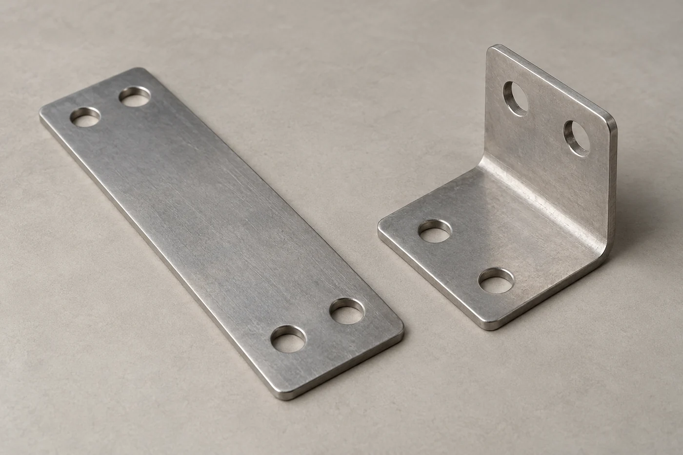
블랭킹·피어싱·성형 순서
프레스 브라켓은 외형을 따내는 블랭킹, 홀을 만드는 피어싱, 굽힘·엠보싱 등의 성형을 조합해 만듭니다. 순서는 평판 상태에서 가공하기 쉬운 특징과 성형 뒤 기준을 잡아야 하는 특징을 구분해 정합니다. 모든 홀을 먼저 만들거나 모든 굽힘을 한 번에 끝내는 방식이 항상 유리한 것은 아닙니다.
| 단계 | 공정에서 정할 것 | 다음 단계에 남기는 영향 |
|---|---|---|
| 블랭크 준비 | 외형·압연 방향·기준 위치 | 재료 유입과 금형 내 위치 안정성 |
| 피어싱·노칭 | 홀·릴리프·절단 간극·버 방향 | 굽힘부 균열·홀 변형·착좌 |
| 예비·최종 성형 | 공구 접근·소재 구속·성형 깊이 | 각도·벽 간격·뒤틀림 |
| 필요한 교정·후가공 | 재성형 또는 최종 홀 가공 | 추가 경화·표면 손상·기준 이동 |
| 마감·검사 | 버·세척·표면처리·최종 측정 | 조립면 상태와 출하 적합성 |
절단면과 후속 성형성
전단된 가장자리에는 눌림·전단면·파단면·버가 생기고, 가장자리 가까운 재료는 가공경화를 겪습니다. 이 영역을 이후에 크게 늘리면 모재의 인장 연신율만으로 예상하기 어려운 균열이 발생할 수 있습니다. 외관상 버가 낮다는 사실만으로 후속 굽힘성이 충분하다고 판단하지 않습니다.
버 방향은 접촉면과 후속 변형 방향을 기준으로 관리합니다. 조립면의 버는 부품을 들뜨게 하고 체결 후 눌리면서 접촉 상태를 바꿀 수 있습니다. 반대로 무리한 연마는 홀 크기와 모서리 형상을 바꾸므로, 제거 대상과 허용되는 모서리 처리를 구체적으로 정합니다.
시제품과 양산 공정의 차이
레이저로 자른 시제품과 금형으로 전단한 양산 블랭크는 절단면 상태가 같지 않을 수 있습니다. 초기 조립성 확인에는 시제품이 유용하지만, 가장자리 성형성과 버 관리는 양산을 대표하는 절단 공정으로 다시 확인해야 합니다. 프로그레시브 금형에서는 파일럿·캐리어·스크랩 배출과 각 공정의 위치 관계도 검토 대상입니다.
아래 3D에서는 평판이 굽힘부를 중심으로 성형되는 형상 관계를 살펴볼 수 있습니다. 실제 금형의 운동, 재료 유입량이나 변형률을 계산한 모델은 아닙니다. 공정 설계에서는 별도로 공구 간섭, 소재 지지, 필요한 하중과 에너지, 성형 후 취출 가능성을 검토합니다.
평판이 브라켓으로 바뀌는 굽힘 구간
INTERACTIVE 3D부하가 걸린 성형 위치의 기하학적 예시입니다. 공구 접촉·국부 박육·마찰·소성 변형은 이 모델에서 계산하지 않습니다.
03형상 안정성과 보강 설계
스프링백·벽 휨·뒤틀림의 교정
금형 안에서 맞던 형상이 취출 후 달라지는 이유 중 하나는 탄성 회복입니다. 성형 중 생긴 응력이 구속 해제 후 재분배되며 각도가 벌어지거나 벽이 휘고 부품이 비틀릴 수 있습니다. 겉으로 보이는 결과가 다르면 같은 보정 방법을 반복 적용하기보다 변형 모드를 먼저 나눠 보아야 합니다.
| 변형 모드 | 확인되는 모습 | 원인 검토 방향 |
|---|---|---|
| 각도 변화 | 평면부는 비교적 곧지만 목표 각도와 차이 | 재료 강도·두께·성형 깊이·공구 조건 |
| 벽 휨 | 벽 자체가 곡면으로 남음 | 굽힘–펴짐 이력·두께 방향 응력 차이 |
| 뒤틀림 | 길이 방향 단면의 회전이 서로 다름 | 비대칭 형상·구속·윤활·소재 위치 |
| 국부 들뜸 | 체결면 일부만 접촉 | 국부 성형·절단 순서·버·표면 손상 |
금형 보정과 공정 변동의 분리
평균 각도가 일정하게 벗어나는 문제와 생산 중 각도가 계속 흔들리는 문제는 다릅니다. 전자는 과굽힘이나 공구 보정으로 접근할 수 있지만, 후자는 소재 두께·강도 편차, 윤활 상태와 위치 결정, 금형 마모 같은 입력 변동을 먼저 확인해야 합니다. 불안정한 공정에서 한 개의 양품에 맞춰 금형만 수정하면 원인을 놓칠 수 있습니다.
재성형과 리스트라이크는 일부 형상 교정에 유효하지만 추가 가공경화와 하중, 표면 압흔을 동반할 수 있습니다. 보정 효과는 취출한 상태에서 확인하고, 다음 절단이나 표면처리 후에도 기능 치수가 유지되는지 살펴야 합니다. 강제로 눌러 맞춘 검사 결과를 자유 상태의 형상으로 기록하지 않습니다.
연구 결과의 적용 범위
NIST 연구진의 스프링백 컵 시험 연구에서는 블랭크 위치와 시험편 채취 위치의 변화가 측정 결과에 영향을 주었습니다. 이는 일반 브라켓의 보정량을 제공하는 결과가 아니라, 성형·측정 조건을 일정하게 해야 비교가 가능하다는 근거입니다. 따라서 시제품 비교에서는 소재와 금형뿐 아니라 지지 위치·측정 위치·구속 상태까지 기록합니다.
정교한 성형 해석도 입력 자료가 맞아야 도움이 됩니다. 재료의 경화 거동, 마찰, 공구와 소재의 접촉, 실제 공정 순서를 반영하고 시험품과 비교해야 합니다. 화면에 변형 형상이 표시된다는 이유만으로 양산 공차나 균열 여유가 검증된 것은 아닙니다.
플랜지·비드·거싯 보강 설계
보강의 핵심은 금속을 무조건 더 쓰는 것이 아니라 하중을 받는 단면의 배치와 연결을 바꾸는 데 있습니다. 평판 가장자리를 세우거나 비드를 성형하면 단면 깊이가 생깁니다. 그러나 보강 효과는 하중 방향과 지지 조건에 따라 달라지므로, 보기 좋은 리브가 반드시 필요한 강성을 만드는 것은 아닙니다.
두께 증가와 단면 형상 변경
단순한 직사각형 단면의 한 방향 굽힘에서는 I = bt³/12입니다. 같은 폭 b에서 두께 t의 변화가 단면2차모멘트 I에 크게 작용함을 보여 줍니다. 플랜지를 세우는 방법은 재료를 중립축에서 떨어진 위치에 배치하는 접근입니다.
이 관계만으로 구멍과 굽힘이 있는 브라켓 전체의 강성을 계산할 수는 없습니다. 실제 부품에는 국부 판 휨, 단면 비틀림, 굽힘부의 회전, 체결부의 미끄럼이 함께 작용할 수 있습니다. 따라서 두께와 보강안은 같은 고정 조건·하중 위치·측정점에서 비교해야 합니다.
| 보강 방법 | 기대하는 역할 | 설계상 대가 |
|---|---|---|
| 가장자리 플랜지 | 단면 높이 확보·자유 가장자리 안정화 | 공간 점유·굽힘 순서·공구 간섭 |
| 비드·엠보스 | 평판부의 국부 형상 강성 부여 | 성형부의 늘어남·반대면 돌출·접촉 간섭 |
| 성형 코너 거싯 | 굽힘 연결부의 회전 억제 보완 | 국부 변형 집중·금형 형상·재료 유입 |
| 별도 거싯·접합 보강 | 지지 경로 추가 | 접합부 강도·열 변형·검사·부품 수 |
체결면 확보와 비드 끝단
볼트 머리나 와셔가 닿는 면에는 충분한 평탄 영역이 필요합니다. 비드를 홀 가까이 넣으면 볼트가 기울어 앉거나 접촉 면적이 줄어들 수 있습니다. 비드 끝단과 급격한 단면 변화부도 힘이 모이는 위치가 될 수 있으므로 곡률 연결, 홀 배치, 남는 폭을 함께 검토합니다.
아래 모델은 보강 전후의 입체 형상을 비교하는 도구입니다. 변형량이나 응력 색상을 성능 수치처럼 제시하지 않습니다. 보강안을 선택할 때에는 제조 가능한 형상인지 확인한 뒤 단품·조립체 해석과 시험으로 필요한 방향의 강성을 검증합니다.
두께 외에 바꿀 수 있는 보강 구조
INTERACTIVE 3D기본 L형 브라켓입니다. 체결 위치와 하중 방향에 따라 굽힘·비틀림·국부 변형의 영향이 달라지므로 형상만으로 허용 하중을 판단하지 않습니다.
04체결 구조와 사용 하중
체결 홀·장공·기준면의 역할
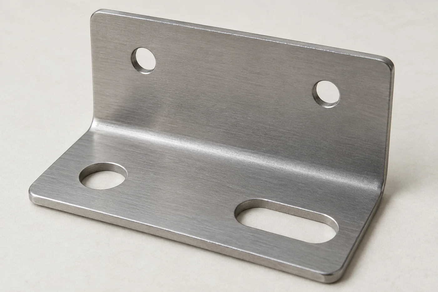
체결 홀은 볼트를 통과시키고, 장공은 특정 방향의 조정을 허용하며, 기준면이나 위치 결정 특징은 조립 위치를 정합니다. 이 세 역할을 도면에서 혼용하면 조립자는 볼트를 끼울 수 있어도 최종 위치를 일정하게 맞추기 어렵습니다. 먼저 무엇이 위치를 결정하는지 정한 뒤 나머지 여유를 배분합니다.
볼트가 홀 안에서 움직일 수 있는 여유와 실제 조립체가 이동할 수 있는 범위는 동일하지 않을 수 있습니다. 다른 체결점, 맞닿는 가장자리, 배선·부품 간섭이 이동을 제한하기 때문입니다. 장공을 길게 늘리기 전에 필요한 조정량과 조인 뒤 유지해야 할 위치, 상대 부품의 공차를 함께 계산합니다.
마찰 전달과 지압 전달
체결면의 마찰로 횡하중을 지지하려면 필요한 체결력과 실제 접촉면의 마찰 조건을 확인해야 합니다. 미끄럼을 허용하거나 별도 위치 결정 구조가 힘을 받는 조립에서는 볼트·핀과 홀의 접촉 면압, 남은 단면과 가장자리 파손을 검토합니다. 볼트를 끼웠다는 사실만으로 어느 경로가 먼저 작동하는지는 정해지지 않습니다.
| 기능 | 확인해야 할 형상·조건 | 놓치기 쉬운 현상 |
|---|---|---|
| 조임과 착좌 | 와셔 크기·평탄 면·접촉 영역 | 얇은 판의 눌림·버에 의한 들뜸 |
| 장공 조정 | 이동 방향·여유·회전 제어 | 조이면서 위치가 끌려감 |
| 위치 반복성 | 명확한 기준·전용 위치 결정 특징 | 큰 체결 홀에 위치 기능까지 기대 |
| 횡하중 전달 | 마찰 조건 또는 지정 지압 경로 | 미끄럼 후 홀 접촉으로 하중 전환 |
| 체결 작업성 | 공구·볼트 삽입·너트 접근 | 설치 후 공구가 들어가지 않음 |
토크와 체결 표면 조건
같은 조임 토크라도 나사와 좌면의 마찰이 달라지면 만들어지는 축력이 달라집니다. 도금·윤활·와셔·상대 재료를 바꿀 때 토크 값만 그대로 복사하지 않습니다. 얇은 브라켓에서는 필요한 축력을 만들기 전에 좌면이 눌리거나 체결면이 휘지 않는지도 확인합니다.
들뜬 브라켓을 볼트로 억지로 눌러 맞추면 조립은 끝나도 초기 응력과 위치 변화가 남을 수 있습니다. 설계상 조립 구속을 허용한다면 허용 틈과 체결 순서, 검사 상태를 명확히 정합니다. 자유 상태 불량을 체결력으로 가리는 방식과 의도된 조립 구속은 구분해야 합니다.
정적 하중·편심·진동·피로 검증
브라켓의 하중 조건은 지지하는 부품의 무게만으로 끝나지 않습니다. 힘의 방향, 작용점과 고정면의 거리, 가속·충격, 케이블이나 배관이 당기는 힘도 기능에 영향을 줄 수 있습니다. 수평·수직 하중과 회전 모멘트를 조립 좌표계에 표시하면 시험과 해석의 경계조건을 맞추기 쉽습니다.
편심 거리와 굽힘 모멘트
단순한 한 방향 예에서는 M = F·e입니다. F는 힘, e는 기준점에서 힘의 작용선까지의 수직 거리이며 M은 그 기준점에 대한 모멘트입니다. 브라켓의 오프셋을 늘리면 같은 힘에도 고정면과 굽힘부가 받아야 할 모멘트가 커질 수 있습니다.
실제 볼트 하중은 접촉면이 어디까지 붙어 있는지와 브라켓·볼트의 상대 강성에 따라 달라집니다. 특히 얇은 발판이 들리는 구조에서는 지레 작용으로 추가 볼트 하중이 생길 수 있습니다. 고정면 전체를 완전 고정한 해석만으로 실제 체결 상태를 대신하지 않도록 접촉·볼트·지지체를 모델링합니다.
| 검증 목적 | 측정·판정 항목 | 별도로 정할 조건 |
|---|---|---|
| 정적 지지 | 하중 중 변위·각도, 제거 후 잔류 변형 | 하중 크기·방향·유지 시간·측정점 |
| 접합 안정성 | 미끄럼·벌어짐·홀 손상·체결 상태 | 볼트·와셔·토크·좌면·지지체 |
| 진동 응답 | 공진·응답 진폭·기능 위치 변화 | 질량·주파수 범위·감쇠·고정 조건 |
| 반복 내구 | 균열·느슨해짐·강성 저하 | 하중 범위·평균 하중·반복 횟수·환경 |
정적 합격과 반복 수명의 구분
한 번의 하중에서 영구 변형이 없었다고 반복 사용 수명이 확인된 것은 아닙니다. 홀과 굽힘 끝단, 버나 흠집, 접합부처럼 응력이 집중되는 곳을 중심으로 반복 하중을 검토합니다. 시험 후에는 눈에 보이는 파손 외에도 미끄럼 누적, 체결 상태, 처짐 변화와 기능 위치를 함께 확인합니다.
아래 조립 모델은 체결 홀·볼트·접촉면과 힘의 위치 관계를 보기 위한 것입니다. 표시한 방향과 분해 상태는 설명용이며 허용 하중이나 볼트 축력을 산출하지 않습니다. 최종 판정에는 실제 소재, 성형 이력, 체결 조건을 반영한 해석 또는 시험 기준을 사용합니다.
체결면과 편심 하중을 함께 보는 조립
INTERACTIVE 3D와셔를 통한 좌면 접촉과 편심 하중의 위치를 함께 표시합니다. 실제 미끄럼·분리·볼트 하중은 축력·마찰·강성에 따라 평가해야 하며 그림에서 계산한 값은 없습니다.
05표면 품질과 치수 검사
표면처리와 조립 기능
도금·도장·세척은 완성품의 마지막 장식 단계가 아닙니다. 표면층은 홀과 틈의 유효 크기, 좌면의 마찰, 이종금속 접촉과 부식 거동에 영향을 줍니다. 따라서 표면처리 전 치수만 맞추는 방식보다 최종 납품 상태에서 무엇을 검사할지 먼저 정해야 합니다.
기능 면별 표면 요구
볼트 좌면, 기준면, 전기적 접촉이 필요한 면, 외관 노출면은 요구가 서로 다를 수 있습니다. 마스킹이나 후가공이 필요한 곳은 범위와 허용 경계를 도면에서 구분합니다. 접지 기능을 요구한다면 금속끼리 닿는 것만으로 충분하다고 가정하지 말고, 표면층과 접촉 유지 조건에 맞는 전기적 검증을 별도로 정합니다.
| 표면·환경 항목 | 기술적으로 확인할 점 |
|---|---|
| 피막 두께 | 홀·장공·끼움부의 최종 여유와 측정 단계 |
| 좌면 상태 | 평탄 접촉·눌림·토크–축력 조건 |
| 절단·굽힘 가장자리 | 피막 연속성·손상·날카로운 모서리 |
| 이종금속 조립 | 접촉 재료·수분·절연 또는 방청 방식 |
| 스테인리스 마감 | 철계 오염·윤활 잔류·용접부 처리 필요성 |
| 포장과 보관 | 부품끼리 마찰·수분 잔류·표면 손상 |
스테인리스강도 가공 후 표면 상태가 나쁘면 기대한 내식성을 얻기 어렵습니다. 철계 공구나 연마재의 오염, 잔류 윤활제, 용접 열변색 등을 사용 환경에 맞게 관리합니다. 세척·산세·부동태화는 같은 작업의 다른 이름이 아니므로 오염 종류와 요구 수준에 맞는 절차를 선택합니다.
표면 결함과 형상 불량의 구분
외관을 균일하게 만들기 위한 연마가 얇은 브라켓의 모서리·홀·평면을 바꿀 수 있습니다. 기능 면의 긁힘, 소재가 접혀 생긴 결함, 눌러 붙은 이물은 단순한 색상 차이와 다르게 분류해야 합니다. 외관 한도 견본에는 관찰 거리와 조명, 기능면 제외 조건을 함께 정하면 검사 해석 차이를 줄일 수 있습니다.
표면처리 후에 기능 홀과 착좌면을 다시 확인하고, 부품이 서로 긁히거나 눌리지 않도록 포장합니다. 굽힘부를 억지로 포개는 포장은 운송 중 형상을 바꿀 수 있습니다. 포장 상태까지 최종 품질 조건으로 연결해야 검사에 합격한 형상이 조립 현장에도 유지됩니다.
기능 기준의 치수·형상 검사
브라켓의 외형 치수가 맞아도 체결 홀 위치와 기준면 방향이 틀리면 조립이 되지 않을 수 있습니다. 검사는 단순 길이, 각도, 면 형상, 홀 위치를 각각 어떤 기능과 연결하는지부터 정합니다. 모든 치수를 무조건 좁게 관리하기보다 조립과 하중 전달에 중요한 특징을 우선 지정합니다.
평면도·평행도·직각도
평면도는 한 면 자체의 형상이고, 평행도와 직각도는 지정한 기준과의 방향 관계입니다. 한 면이 평평하다고 상대 면과 평행한 것은 아닙니다. 굽힘각만 확인해도 홀 중심의 조립 위치는 남을 수 있으므로, 기능 기준에서 홀 위치와 면 방향을 함께 측정합니다.
| 기능 특징 | 주된 확인 내용 | 측정 조건의 핵심 |
|---|---|---|
| 장착 기준면 | 평면도·국부 들뜸·접촉 영역 | 지지점과 자유/구속 상태 |
| 상대 체결 홀 | 크기·위치·장공 방향 | 동일 기준 좌표계·피막 포함 여부 |
| 굽힘부 | 각도·내측 반경·균열 | 평면부 선정·모서리 제외 규칙 |
| U형 벽 또는 Z형 단차 | 간격·평행도·높이 누적 | 측정 위치·상대 기준면 |
| 모서리·버 | 잔류 버·날카로움·가장자리 손상 | 검사 방향·배율·합의된 한도 |
얇은 판은 측정자의 누르는 힘이나 고정구의 구속으로 형상이 바뀔 수 있습니다. 자유 상태와 지정된 조립 구속 상태를 구분하고, 같은 지지 위치·체결 조건으로 반복 측정합니다. 정반 위에 놓았다는 설명만으로는 어느 면이 기준이었고 어디를 눌렀는지 충분히 재현되지 않습니다.
측정값의 신뢰도
측정기 표시 분해능이 곧 측정 불확도는 아닙니다. 재장착, 측정자, 측정 위치와 온도, 평가 알고리즘에 따른 차이를 확인해야 합니다. 형상이 유연하거나 공차가 엄격한 특징은 반복 측정과 측정시스템 검토로 판정의 흔들림을 먼저 파악합니다.
측정 성적서에는 도면 개정, 소재·표면 상태, 기준 설정, 검사 시점과 판정 기준을 연결합니다. 기능 게이지는 빠르게 조립 가능성을 확인하는 데 유용하지만, 어떤 치수 조합을 검증하고 무엇은 검증하지 못하는지 정의해야 합니다. 게이지 합격과 모든 개별 치수의 합격은 자동으로 같은 의미가 되지 않습니다.
06검증·양산 관리·제작 의뢰
시제품 검증과 양산 관리
시제품은 설계한 형상과 공정이 기능을 만들 수 있는지 확인하는 단계입니다. 양산 관리는 그 결과를 반복해서 유지할 수 있는지를 확인합니다. 한 개의 양품을 만들었다는 사실과 소재 로트·작업 교대·금형 마모가 바뀌어도 같은 결과를 얻는다는 사실은 구분해서 증명해야 합니다.
실제 고정 조건을 반영한 시험
브라켓 시험에는 상대 구조물, 볼트와 와셔, 조임 순서와 토크, 하중의 위치를 명시합니다. 지나치게 단단한 시험 지그가 실제 지지체의 휨을 가리면 사용 중 거동과 다를 수 있습니다. 변위는 브라켓의 기능점에서 측정하고, 시험기와 지그 자체의 변형이 얼마나 포함되는지도 확인합니다.
| 단계 | 확인할 질문 | 남겨야 할 결과 |
|---|---|---|
| 초기 시제품 | 형상·조립 경로·공구 접근이 성립하는가 | 간섭·조정량·수정 이력 |
| 공정 시제품 | 양산 공정으로 같은 기능을 만드는가 | 절단면·성형·최종 치수와 소재 조건 |
| 성능 검증 | 지정 하중·환경에서 기능을 유지하는가 | 변위·잔류 변형·반복 시험 판정 |
| 초기 양산 | 설정과 로트가 달라도 관리되는가 | 공정 입력·검사 결과·이상 조치 |
| 지속 생산 | 마모·변경 이후에도 기준이 유지되는가 | 추세·보전·변경 승인·재검증 |
공정 관리에서는 최종 치수만 기록하지 않고 소재 두께·등급, 윤활, 금형 설정과 보전 상태처럼 결과를 만드는 입력도 연결합니다. 불량이 발생하면 어느 시점부터 달라졌는지 추적할 수 있어야 합니다. 초기·중간·종료 시점의 확인과 이상 발생 후 격리·재확인 범위는 위험과 생산 방식에 맞춰 정합니다.
안정된 데이터와 공정능력
Cpk와 같은 지수는 적절한 측정시스템과 안정된 공정, 충분하고 대표성 있는 데이터를 전제로 해석해야 합니다. 서로 다른 소재 로트나 설정의 데이터를 구분 없이 섞거나, 소수 시제품으로 지수만 계산하면 실제 변동을 잘못 설명할 수 있습니다. 지수의 목표와 계산 방법은 고객 요구와 데이터 특성에 맞춰 합의합니다.
설계나 소재, 절단 방식, 표면처리가 바뀌면 무엇을 다시 검증할지도 정해야 합니다. 예를 들어 홀 위치를 옮기면 조립성뿐 아니라 굽힘 중 홀 변형과 남은 단면이 바뀝니다. 변경 영향이 닿는 기능과 공정을 찾아 해당 검사·시험을 갱신하는 것이 합리적입니다.
금속 브라켓 제작 도면과 발주 조건
금속 브라켓 제작을 검토할 때 3D 형상은 공간 관계를, 2D 도면은 기능 치수와 판정 기준을 전달합니다. 두 자료의 개정을 일치시키고 서로 다른 지시가 있을 때 우선순위를 정합니다. 전개도는 공정 조건에 따라 조정될 수 있으므로, 제공된 전개가 참고인지 확정 제조 데이터인지도 구분합니다.
| 전달 자료 | 필요한 내용 | 결정에 도움이 되는 이유 |
|---|---|---|
| 기능·조립 정보 | 상대 부품·기준면·하중 방향·설치 공간 | 중요 특징과 체결 경로를 정함 |
| 소재·형상 | 등급·공급 상태·두께·압연 방향·반경 | 성형성과 전개·금형 조건 검토 |
| 공차·검사 | 기능 치수·기하 공차·자유/구속 상태 | 측정과 합격 기준 일치 |
| 표면·마감 | 피막·기능면·버·외관·세척 | 최종 치수와 조립면 관리 |
| 수량·일정 | 시제품·예상 생산량·설계 변경 가능성 | 공정과 금형 투자 범위 판단 |
| 납품·검증 | 단품/조립체·시험·성적서·포장 | 공급 범위와 검증 책임 명확화 |
금형 투자와 단가의 비교
설계가 자주 바뀌는 소량 부품은 전용 금형보다 범용 절단·성형 공정이 유리할 수 있습니다. 반복 생산에서는 전용 금형이 공정 통합과 생산성에 도움이 될 수 있지만, 초기 투자와 수정·보전 비용을 포함해야 합니다. 수량 하나만으로 공정을 정하지 않고 형상 안정성, 검사 난이도와 납기를 함께 비교합니다.
모든 면과 홀에 같은 수준의 엄격한 공차를 넣으면 기능 개선 없이 검사와 교정 비용이 늘어날 수 있습니다. 반대로 중요한 체결면과 홀의 관계를 일반 공차에만 맡기면 현장에서 조정 비용이 생깁니다. 도면 검토의 목적은 중요한 곳을 명확히 관리하고 나머지에는 제조 가능한 여유를 주는 것입니다.
도면·공정·검사의 기능 일치
브라켓의 완성도는 각도를 맞춘 외형만으로 결정되지 않습니다. 하중 경로에 맞는 단면, 성형 가능한 반경과 홀 배치, 안정된 체결면, 최종 상태에서 재현 가능한 검사 기준이 연결되어야 합니다. 이 연결이 명확하면 시제품 수정의 이유를 설명하고 양산 변경도 관리하기 쉽습니다.
English Edition · Metal Bracket Forming, Reinforcement and Joint Quality
Metal bracket manufacturing must control more than the outline. A small angle error or a lifted mounting face changes assembly position and load transfer. Thickness alone may not solve the problem because the bends, stiffeners, fasteners and supporting structure act together. Design, forming and final inspection need a common functional basis.
This article examines general formed sheet-metal brackets through material selection, development and hole placement, springback, flange/bead reinforcement, fastening and repeated loading. Three photographic illustrations and three interactive 3D models are conceptual aids, not photographs of supplied products or validated performance data.
Geometry and load paths
Connect L, U and Z bracket functions with material, thickness and reinforcement.
Forming and geometric variation
Link flat patterns, holes, cut edges and operation order to springback.
From fastening to validation
Define datums, slots, eccentric loading, finishing, inspection and purchasing inputs.
01Function and material selection
Start with the bracket’s load path
Metal bracket manufacturing starts before choosing an L shape or counting holes. First define what the bracket supports, where it must remain, and how forces reach the supporting structure. Similar-looking brackets can act as supports, locators or spacers, each with different critical surfaces and dimensions.
Load enters through the interface with the mounted component, passes through the plate, bends and stiffeners, and exits through the joint into the supporting structure. Examine narrow transitions, holes near bends and long projections along this path. Multiple bolts do not necessarily share load equally because bracket flexibility and contact conditions affect the distribution.
Choose L, U and Z forms around the installation
| Form | Structural purpose | Associated design checks |
|---|---|---|
| L | Connect two differently oriented faces | Arm bending, bend rotation and bolt access |
| U | Support or surround a component between walls | Wall spacing, opening, parallelism and insertion |
| Z | Connect parallel faces at different elevations | Offset, eccentric moment and accumulated bend variation |
| Flanged or reinforced | Modify section depth and the load path | Envelope, local formability and clear mounting faces |
For an L bracket supporting a projecting component, moving the force farther from the mounting face increases the bending moment without increasing the force itself. Before changing material, review the projection, fixing-point spacing and load-entry position. Shortening the load path addresses the problem differently from increasing sheet thickness.
Separate support, location and fastening
Distinguish support by a surface, location by a pin or defined hole, and clamping by a bolt. Enlarging a clearance hole may ease assembly without improving positioning repeatability. The assembly drawing should identify the reference surfaces, permitted adjustment directions and the position that must be retained after tightening.
The discussion concerns sheet-metal brackets used with equipment, housings and frames. Photographic illustrations and interactive 3D models explain geometry and function. They do not represent measured production dimensions, rated loads or validated analysis results for a particular supplied product.
Specify material, thickness and rolling direction together
A material family alone does not define a forming process. Specify the grade, delivery condition, thickness tolerance and surface condition. Differences in strength and processing history within a family change forming loads, springback and the margin against bend cracking.
| Material choice | Potential benefit | Additional checks |
|---|---|---|
| Low-carbon steels | Balance formability and cost | Corrosion protection and post-coating fit |
| Stainless steels | Corrosion and surface performance suited to service | Grade, work hardening, lubrication and contamination |
| Aluminum alloys | Lower mass and manufacturability | Alloy/temper bendability, stiffness and dissimilar-metal contact |
| High-strength steels | Yield resistance and potential mass reduction | Springback, cut-edge formability and tooling loads |
Strength and stiffness are different requirements
Strength concerns resistance to permanent deformation or failure; stiffness concerns movement under load. Replacing steel with a higher-yield grade does not reduce elastic deflection in the same proportion when geometry is unchanged. A bracket that must hold position needs separate limits for stress and for displacement or angular change.
Increasing thickness changes section properties, mass, cutting/forming loads and feasible feature sizes. A thinner sheet with stiffening features may provide adequate stiffness, but local cracking, distortion and additional operations must be reassessed. Optimizing material, thickness or geometry in isolation can transfer cost elsewhere.
Carry rolling direction into the flat pattern
Bendability can depend on the relationship between the bend line and rolling direction. Where the supplier gives directional bend-radius limits, use data matching the grade, thickness and delivery condition. A part with perpendicular bends cannot orient every bend favorably, so prioritize its most demanding bend when reviewing stock orientation and geometry.
If orientation is controlled, define how it remains identifiable from coil or sheet through blanking and forming. Without that record, an orientation difference between prototypes and production can be difficult to diagnose. Use the same material-condition description in drawings, trial records and process instructions.
02Flat-pattern design and press operations
Connect flat length, bend radius and hole placement
Adding the finished outside lengths does not directly give an accurate blank length. Bending compresses the inside and stretches the outside, so development accounts for a neutral layer between them. A CAD flat pattern is useful only when its bend radius and allowance data correspond to the intended process.
K-factor is not a universal material constant
The neutral-layer length of one bend can be written as BA = θ(R + Kt). BA is bend allowance, R the inside radius, t the thickness, and θ the angle through which the sheet is bent, expressed in radians. K is the distance from the inside surface to the neutral layer divided by thickness.
This is a geometric relation for development. Adjusting K merely to make a CAD model fit can conceal errors in actual angle, radius or flange length. Calibrate the bend table using trials with the same stock, tooling and forming method, and consistently distinguish outside virtual intersections from tangent points.
| Drawing/development item | Common ambiguity | Verification |
|---|---|---|
| Bend angle | Confusing included angle and rotation angle | Define the angle and measured surfaces |
| Inside radius | Assuming the tool nose equals the finished radius | Relate the forming method to measured parts |
| Hole-to-bend spacing | Comparing only center distances | Check hole edge, bend tangent and tool contact region |
| Bend-end relief | Treating a notch as merely cosmetic | Review tearing, interference and remaining section |
Decide whether holes are made before or after forming
A hole near the deforming region or tool contact zone can elongate or distort. A single thickness multiplier is not a universal minimum hole-to-bend distance. Review inside radius, die support, hole shape and orientation, and the permitted distortion together.
When the functional hole cannot be moved, consider different tooling or piercing/machining after forming. A secondary operation can locate from the formed part, but needs its own fixture and tool access. Resolve hole location and operation order together to compare assembly accuracy with manufacturing cost.
Blanking, piercing and forming order affect the finished geometry
Stamped brackets combine blanking of the outline, piercing of holes, and operations such as bending or embossing. Sequence features that are easiest to produce flat separately from those that need a formed datum. Making every hole first or completing every bend in one operation is not always the best route.
| Stage | Define in the process | Effect on later operations |
|---|---|---|
| Blank preparation | Outline, stock direction and location | Material flow and stable positioning |
| Piercing/notching | Holes, reliefs, clearance and burr direction | Bend cracking, hole distortion and seating |
| Preforming/final forming | Tool access, restraint and forming depth | Angle, wall spacing and twist |
| Required correction/secondary work | Restriking or final hole production | Further hardening, marks and datum change |
| Finishing/inspection | Deburring, cleaning, finish and final measurement | Assembly interfaces and release conformity |
The cut edge becomes the starting condition for forming
Mechanical shearing creates rollover, burnished and fractured zones, and a burr; adjacent material is work hardened. Stretching that region later can produce cracking that a bulk tensile elongation value alone does not predict. A visually small burr is therefore not sufficient evidence of good downstream formability.
Control burr direction in relation to the assembly interface and subsequent deformation. A burr on a mating face can hold a part away from its support and then crush during tightening, changing the contact. Excessive grinding can alter hole size and edge geometry, so define both what must be removed and the permitted edge treatment.
Record differences between prototype and production routes
Laser-cut prototypes and mechanically sheared production blanks may have different edge conditions. Prototypes are useful for early fit checks, but edge formability and burr control should be revalidated with the intended production cutting process. A progressive die also requires review of pilots, carriers, scrap evacuation and the positional relationship between stations.
The 3D below shows the geometric relationship between a flat blank and its bent form. It does not calculate die motion, material draw-in or strain. Process design separately checks tool interference, material support, required force and energy, and removal of the formed part.
The bend zone that turns a blank into a bracket
INTERACTIVE 3DA geometric example of the loaded forming position. Tool contact, local thinning, friction and plastic deformation are not calculated in this model.
03Shape stability and reinforcement
Distinguish angular springback, wall curl and twist
Elastic recovery is one reason a part changes shape after leaving the die. Forming stresses redistribute as constraints are released, allowing angle changes, wall curl or twist. Different visible modes call for diagnosis before repeatedly applying the same compensation.
| Mode | Observed shape | Investigation direction |
|---|---|---|
| Angular change | Faces are fairly straight but angle is off target | Material strength, thickness, forming depth and tooling |
| Wall curl | The wall itself remains curved | Bending/unbending history and through-thickness stress gradient |
| Twist | Sections rotate differently along the part | Asymmetric geometry, restraint, lubrication or blank placement |
| Local stand-off | Only part of a mating face touches | Local forming, trimming order, burrs or surface damage |
Separate systematic compensation from process variation
A consistent mean-angle offset differs from an angle that varies throughout a run. Overbending or tool compensation can address the former; the latter first requires review of thickness/strength variation, lubrication, location and tool wear. Adjusting a die to one good part in an unstable process can obscure the cause.
Reforming and restriking can correct certain geometries, but can add work hardening, load and surface impressions. Verify correction after unloading and confirm that later cutting or finishing does not invalidate functional dimensions. A part forced into shape in an inspection fixture must not be reported as having that free-state geometry.
Translate research within its tested scope
A NIST study of the springback cup test found that blank alignment and specimen extraction location affected measured results. It does not supply a compensation value for general brackets; it demonstrates why forming and measurement conditions must be controlled for comparison. Prototype comparisons should therefore record support points, measurement locations and restraint as well as material and tooling.
Detailed forming simulation is useful only with suitable inputs. It needs material hardening behavior, friction, contact and the actual operation sequence, followed by comparison with physical trials. A displayed deformed shape alone does not validate production tolerances or the margin against cracking.
Use flanges, beads and gussets in the required direction
Reinforcement changes the distribution and connection of material along the loaded section. Turning up an edge or forming a bead creates section depth. Its benefit depends on load direction and support conditions; an attractive rib is not necessarily effective for the stiffness actually required.
Compare thicker stock with a different section
For bending of a simple rectangular section about the relevant axis, I = bt³/12. At constant width b, thickness t strongly affects the second moment of area I. Forming a flange instead places material farther from the neutral axis.
That relation alone cannot calculate the stiffness of a complete bracket containing holes and bends. Local plate bending, section twist, bend rotation and joint slip may all contribute. Compare thickness and reinforcement alternatives under the same mounting conditions, load position and measurement locations.
| Reinforcement | Intended role | Design cost or trade-off |
|---|---|---|
| Edge flange | Provide section depth and stabilize a free edge | Space, bend sequence and tooling interference |
| Bead/emboss | Give a plate local geometric stiffness | Stretching, reverse-side projection and interface clearance |
| Formed corner gusset | Help restrain rotation at a bend | Concentrated deformation, tooling and material flow |
| Separate joined gusset | Add a supporting load path | Joint strength, thermal distortion, inspection and part count |
Protect mounting faces and review bead terminations
Bolt heads and washers need an adequate seating region. A bead too close to a hole can tilt the fastener or reduce contact area. Bead terminations and abrupt section transitions can also concentrate load, so review their radii, hole placement and remaining ligament together.
The model below compares the three-dimensional geometry of reinforcement alternatives. It does not present displacement or stress colors as performance data. First establish manufacturability, then use component/assembly analysis and testing to verify stiffness in the required direction.
Reinforcement choices beyond sheet thickness
INTERACTIVE 3DA plain L bracket. Fastener locations and load direction affect bending, torsion and local deformation; shape alone does not establish allowable load.
04Fastening and service loads
Clearance holes, slots and datums have different jobs
Clearance holes admit fasteners, slots permit adjustment in a chosen direction, and datums or locating features establish position. Mixing these functions can produce an assembly that accepts its bolts but cannot be positioned consistently. Define the locating features first, then allocate the remaining clearances.
Clearance around a bolt is not necessarily the available movement of the complete assembly. Other fixings, contact edges and surrounding parts may constrain it. Before lengthening a slot, establish the required adjustment, retained position after tightening and tolerances of the mating components.
Define whether friction or bearing carries the load
A joint that resists transverse force by friction needs adequate clamping force and verified interface friction. Where slip is permitted, or a separate locator carries load, assess bolt/pin bearing against holes, the remaining net section and edge failure. Installing a bolt does not by itself establish which load path acts first.
| Function | Geometry/condition to check | Commonly missed behavior |
|---|---|---|
| Clamping and seating | Washer size, flat area and contact footprint | Sheet indentation or burr-induced stand-off |
| Slot adjustment | Travel direction, clearance and rotational control | Position dragged during tightening |
| Position repeatability | Defined datums and dedicated locators | Expecting a large clearance hole to locate precisely |
| Transverse load transfer | Friction or a defined bearing path | Load transfers into hole contact after slip |
| Assembly access | Tool, bolt insertion and nut access | No tool access after installation |
Specify tightening torque with surface conditions
The same torque can create different preload when thread or seating friction changes. Do not carry over a torque value unchanged after changing plating, lubrication, washers or mating materials. In a thin bracket, also check whether the seating region indents or bends before the required clamp force is achieved.
Bolting a distorted bracket forcibly flat can leave assembly stress and positional changes. If restrained assembly is intentional, specify the allowed gap, tightening sequence and inspection condition. Deliberate assembly restraint is different from using clamp force to conceal a free-state defect.
Verify static load, eccentricity, vibration and fatigue separately
Bracket loading extends beyond the weight of the supported component. Direction, distance from the mounting face, acceleration, impact and forces from cables or pipes can matter. Defining forces and moments in the assembly coordinate system makes test and analysis boundary conditions easier to align.
Eccentricity changes the effect of the same force
For a simple planar case, M = F·e. F is the force and e the perpendicular distance from the reference point to its line of action; M is the moment about that point. Increasing a bracket offset can increase the moment at the mounting face and bend without changing the force.
Actual bolt loads depend on the remaining contact region and the relative stiffness of bracket and fasteners. A flexible foot that lifts can introduce additional bolt loading through prying. Model contact, bolts and support flexibility as needed rather than treating an entirely fixed mounting face as equivalent to the actual joint.
| Verification purpose | Measure/assess | Conditions to specify |
|---|---|---|
| Static support | Loaded displacement/angle and residual deformation after unloading | Force, direction, dwell and measurement locations |
| Joint stability | Slip, separation, hole damage and fastening condition | Bolts, washers, torque, seating and supporting structure |
| Vibration response | Resonance, response amplitude and functional movement | Mass, frequency range, damping and mounting |
| Cyclic durability | Cracks, loosening and stiffness loss | Load range, mean load, cycles and environment |
Do not turn a static pass into a fatigue-life claim
Absence of permanent deformation in a single load case does not establish service life. Review repeated loading around stress-concentration sites such as holes, bend ends, burrs, scratches and joints. After testing, assess accumulated slip, fastening condition, deflection change and functional position as well as visible fracture.
The assembly model below explains fastener holes, bolts, contact surfaces and the position of loading. Its directions and exploded states are illustrative and do not calculate load capacity or bolt preload. Final acceptance needs analysis or test criteria reflecting the actual material, forming history and fastening conditions.
Assembly contact faces and eccentric loading
INTERACTIVE 3DWasher seating and the position of an eccentric load are shown together. Actual slip, separation and bolt loading require preload, friction and stiffness evaluation; no calculated results are shown.
05Surface quality and dimensional inspection
Surface finishing affects appearance and assembly function
Plating, painting and cleaning are more than cosmetic finishing steps. Surface layers affect effective hole and gap sizes, seating friction, dissimilar-metal contact and corrosion behavior. Define inspection in the final delivery condition instead of considering only pre-finish dimensions.
Assign requirements to each functional surface
Bolt seats, datums, electrically conductive interfaces and visible surfaces may need different treatments. Define masking or secondary-finishing areas and their permitted boundaries on the drawing. Where grounding is required, metal-to-metal proximity alone is insufficient; specify electrical verification appropriate to the surface layer and retained contact.
| Surface/environment item | Technical question |
|---|---|
| Coating thickness | Final hole/slot/fit clearance and inspection stage |
| Seating condition | Flat contact, indentation and torque–preload conditions |
| Cut/bent edges | Coating continuity, damage and sharp edges |
| Dissimilar-metal assembly | Material pair, moisture and insulation/protection strategy |
| Stainless finishing | Iron contamination, lubricant residue and weld treatment needs |
| Packaging/storage | Part-to-part rubbing, retained moisture and finish damage |
Stainless steel can lose expected corrosion performance when fabrication leaves an unsuitable surface. Control iron contamination, lubricant residues and weld heat tint according to the service environment. Cleaning, pickling and passivation are not interchangeable names for one operation; select a procedure for the contamination and performance required.
Distinguish surface defects from geometric defects
Cosmetic polishing can change the edges, holes or faces of a thin bracket. Scratches on functional surfaces, folded material defects and embedded debris differ from mere color variation. Appearance reference samples are more useful when viewing distance, lighting and exceptions for functional surfaces are also defined.
Recheck functional holes and seating surfaces after finishing and pack parts to prevent rubbing or indentation. Forcing bent parts into a tight nesting arrangement can alter their shape during transport. Treat packaging as part of final quality so that an accepted geometry reaches assembly intact.
Derive dimensions, geometry and inspection datums from function
Correct overall dimensions do not guarantee assembly when mounting-hole positions or datum orientations are wrong. Start inspection planning by linking lengths, angles, surface form and hole positions to function. Prioritize features governing assembly and load transfer instead of applying unnecessarily tight limits everywhere.
Separate flatness, parallelism and perpendicularity
Flatness describes the form of a surface; parallelism and perpendicularity describe orientation relative to a specified datum. A flat face is not necessarily parallel to another. Checking only the bend angle can also miss an assembly-hole position error, so measure both location and orientation from functional datums.
| Functional feature | Main checks | Essential measurement condition |
|---|---|---|
| Mounting datum face | Flatness, local stand-off and contact region | Support points and free/restrained condition |
| Mating holes | Size, position and slot direction | Common datum frame and coating condition |
| Bend region | Angle, inside radius and cracking | Selected planar areas and edge exclusions |
| U walls or Z offsets | Spacing, parallelism and accumulated height | Measurement locations and reference face |
| Edges and burrs | Residual burrs, sharpness and damage | Viewing direction, magnification and agreed limits |
Thin sheet can deform under probe force or fixture restraint. Distinguish free-state inspection from a specified assembled restraint and repeat measurements with the same supports and fastening conditions. Merely saying that a part was placed on a surface plate does not reproduce its datum or the locations where force was applied.
Check confidence in the measurement itself
Instrument display resolution is not measurement uncertainty. Repositioning, operators, sampling locations, temperature and evaluation algorithms can affect results. For flexible geometry or demanding tolerances, repeated measurements and a measurement-system review help identify decision variability before judging the process.
Link the report to drawing revision, material/finish condition, datum setup, inspection stage and acceptance criteria. A functional gauge can check assembly quickly, but its validated feature combination and exclusions must be defined. Passing a gauge is not automatically equivalent to passing every individual dimension.
06Validation, production control and inquiries
Prototype validation and production control answer different questions
A prototype demonstrates whether the design and process can deliver the function. Production control establishes whether that result can be sustained. Producing one conforming part differs from maintaining conformity through material lots, shift changes and tool wear.
Make the test mounting representative
Define the mating structure, fasteners and washers, tightening sequence/torque and load application point in a bracket test. An overly rigid fixture can conceal support flexibility present in service. Measure displacement at the functional point and establish how much machine or fixture compliance is included.
| Stage | Question | Record |
|---|---|---|
| Early prototype | Do geometry, insertion and tool access work? | Interference, adjustment and design revisions |
| Process prototype | Does the production route produce the same function? | Edges, forming, final dimensions and material condition |
| Performance validation | Is function retained under specified loads/environment? | Displacement, permanent set and cyclic-test decisions |
| Initial production | Are settings and lot variation controlled? | Process inputs, inspection and response actions |
| Ongoing production | Are requirements maintained after wear or changes? | Trends, maintenance, change approval and revalidation |
Production records should connect final dimensions with inputs such as material thickness/grade, lubrication, die settings and maintenance. When a defect appears, the records should help identify when conditions changed. Start, in-process and end checks, containment and reinspection scope should match the risk and production method.
Interpret capability indices from stable data
Indices such as Cpk require a suitable measurement system, a stable process, and sufficient representative data for interpretation. Mixing unlike lots/settings or calculating an index from a few prototypes can misrepresent variation. Agree targets and calculation methods according to customer requirements and the data characteristics.
Define revalidation after changes to design, material, cutting or finish. Moving a hole, for example, changes not only fit but potential bend distortion and the remaining section. Identify the affected functions and operations, then update the relevant inspections and tests.
Complete the drawing and purchasing requirements
For metal bracket manufacturing, the 3D model communicates spatial geometry while the 2D drawing defines functional dimensions and acceptance requirements. Align their revisions and establish precedence if instructions conflict. State whether a supplied flat pattern is reference information or approved manufacturing data, because development can depend on the process.
| Information | Required detail | Why it matters |
|---|---|---|
| Function and assembly | Mating parts, datums, load direction and envelope | Define critical features and the joint load path |
| Material and geometry | Grade, condition, thickness, rolling direction and radii | Review formability, development and tooling |
| Tolerance and inspection | Functional dimensions, geometric tolerances and restraint state | Align measurement and acceptance |
| Finish | Coating, functional areas, burrs, appearance and cleaning | Control final fit and interfaces |
| Quantity and schedule | Prototypes, expected volume and design-change likelihood | Choose the process and tooling investment |
| Supply and validation | Part/assembly scope, tests, reports and packaging | Define responsibilities and deliverables |
Compare tooling investment and unit cost over the same program
Low-volume parts with frequent design changes may favor flexible cutting and forming routes over dedicated dies. Repeated production can benefit from integrated die operations and productivity, but the comparison must include investment, modifications and maintenance. Quantity alone is insufficient; also compare design stability, inspection complexity and lead time.
Applying equally demanding tolerances to every face and hole can increase inspection and correction cost without improving function. Leaving critical mounting-face and hole relationships to general tolerances can instead transfer cost to assembly. Drawing review should control the important features clearly while allowing practical manufacturing freedom elsewhere.
Make drawings, process and inspection describe the same function
Bracket quality is not defined by a correct-looking bend alone. The load path, section geometry, formable radii and holes, stable mating faces and reproducible final-state inspection must agree. This makes prototype revisions explainable and production changes manageable.
The ID METAL press-forming and NCT-processing pages provide context for discussing manufacturing scope. Include drawings, assembly conditions, quantity/schedule and required inspection records with an inquiry. The manufacturing route and verification scope for an individual geometry are agreed from those inputs.
추가 정보
검색엔진용 요약
금속 브라켓 제작은 하중을 전달하는 형상과 프레스 공정, 체결 조건을 함께 정하는 작업입니다. 소재·두께·굽힘 반경·홀 배치와 스프링백을 검토하고, 보강 구조·표면처리·최종 치수 검사와 조립체 검증을 같은 기능 기준으로 연결해야 안정된 품질을 관리할 수 있습니다.
핵심 포인트 정리
- L·U·Z 형상은 설치 공간, 지지 방향과 하중 경로를 기준으로 선택합니다.
- 소재 등급·공급 상태·두께·압연 방향을 함께 정하고 강도와 강성 요구를 구분합니다.
- 전개와 홀 배치는 실제 굽힘 반경·공구 지지·공정 순서에 맞춰 검토합니다.
- 각도 스프링백·벽 휨·뒤틀림을 구분하고 금형 보정과 입력 변동을 따로 관리합니다.
- 플랜지·비드·거싯은 하중 방향에 맞춰 설계하고 체결면·공구 접근을 확보합니다.
- 기준면·장공·체결력·표면처리와 자유/구속 측정 상태를 정한 뒤 실제 조립 조건으로 검증합니다.
FAQ
금속 브라켓은 두꺼울수록 좋은가요?
두께 증가는 강성과 강도에 도움이 될 수 있지만 질량·성형 하중·가공 가능한 반경도 바꿉니다. 돌출 길이와 하중 경로, 플랜지나 보강 형상을 함께 비교하고 필요한 변위·하중 기준으로 선택해야 합니다.
고강도강으로 바꾸면 처짐도 크게 줄어드나요?
항복강도와 탄성 강성은 다른 특성입니다. 같은 형상에서 강종의 항복강도가 높아져도 탄성 처짐이 같은 비율로 줄지는 않습니다. 처짐은 탄성계수·단면·길이·지지 조건을 따로 검토해야 합니다.
홀과 굽힘선은 얼마나 떨어뜨려야 하나요?
모든 브라켓에 적용되는 하나의 거리 규칙으로 정하기 어렵습니다. 두께·내측 반경·공구 접촉과 지지 조건, 홀 형상과 허용 변형을 함께 확인합니다. 필요한 경우 형상 변경이나 성형 후 홀 가공을 비교합니다.
장공을 넣으면 조립 공차가 해결되나요?
장공은 지정 방향의 조정을 허용하지만 위치 반복성과 체결 후 유지까지 자동으로 해결하지는 않습니다. 위치 결정 기준, 이동 범위, 회전 제어와 체결면의 하중 전달 방식을 함께 정해야 합니다.
비드나 거싯은 어디에 넣어야 하나요?
하중이 지나가는 경로와 변형 모드를 기준으로 위치를 정합니다. 볼트 좌면을 침범하지 않도록 하고 끝단의 급격한 형상 변화, 국부 성형성과 주변 간섭을 확인합니다. 보강 효과는 실제 고정 조건의 해석이나 시험으로 검증합니다.
성형품을 볼트로 눌러 평평하게 조립해도 되나요?
의도된 조립 구속인지 먼저 구분해야 합니다. 허용 틈·체결 순서·토크·검사 상태가 지정되지 않은 채 뒤틀림을 억지로 누르면 초기 응력과 위치 변화가 남을 수 있습니다. 자유 상태와 조립 상태의 판정 기준을 각각 정합니다.
시제품이 조립되면 양산 검증도 끝난 건가요?
조립 가능성 확인과 반복 생산의 안정성은 다릅니다. 시제품과 양산의 절단면·성형 조건 차이를 확인하고 최종 표면 상태의 치수와 하중 시험, 소재·설정·마모 변동의 관리 계획까지 연결해야 합니다.
브라켓 제작 문의에 어떤 자료가 필요한가요?
같은 개정의 2D 도면과 3D 형상, 소재·두께·표면처리, 상대 부품과 하중 조건, 기능 치수·검사 기준을 준비합니다. 수량·일정·설계 변경 가능성과 단품 또는 조립체의 공급 범위도 함께 전달하면 공정과 검증 범위를 정하기 쉽습니다.
관련 주제 확장 설명
프레스 절단면과 후속 성형
블랭킹·피어싱의 절단 간극과 공구 상태는 버뿐 아니라 후속 성형의 가장자리 거동에도 영향을 줍니다. 시제품과 양산의 절단 방식이 다르면 기능상 민감한 가장자리를 양산 조건으로 다시 확인합니다.
브라켓의 조립 공차 누적
단일 굽힘각이 맞아도 두 굽힘과 홀 위치, 상대 부품의 치수가 누적되면 조립 위치가 달라집니다. 기능 기준면에서 체결 위치까지의 치수 경로와 필요한 조정량을 함께 검토합니다.
최종 표면과 착좌 품질
피막·버·이물과 얇은 판의 눌림은 볼트 좌면과 기준면의 접촉을 바꿀 수 있습니다. 표면처리 전 측정만으로 끝내지 않고 최종 납품 상태의 기능 치수와 조립 결과를 연결합니다.
내부 링크
절단 공정은 프레스 금형 클리어런스와 절단면 품질, 조립 위치는 정밀부품 공차 누적, 최종 이물 관리는 정밀 금속부품 세척과 청정도에서 이어서 살펴볼 수 있습니다.
부품 형상과 수량에 맞는 공정은 프레스 가공 및 NCT 가공 안내와 함께 검토할 수 있습니다. 도면·조립 조건·수량·일정과 필요한 검사 자료는 제품문의·개발의뢰로 전달해 주세요.