
도금한 뒤 치수가 달라진다:
정밀 금속부품의 도금 여유 설계
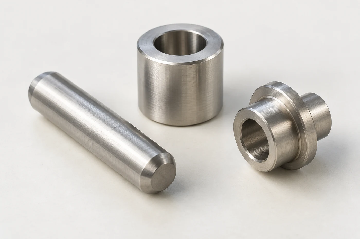
가공에서는 맞던 축과 구멍이 도금 후에는 조립되지 않을 수 있습니다. 축의 외경은 커지고 홀의 내경은 작아지기 때문입니다. 도금 여유 설계는 몇 μm의 금속층이 최종 치수와 끼워맞춤에 어떻게 반영되는지 정하고, 가공 공차와 피막 공차를 함께 배분하는 작업입니다.
작은 핀과 부시, 프레스 단자와 나사 부품에서는 편측 두께와 지름 변화, 다층 피막과 국부 분포를 구분해야 합니다. 완성 치수와 필요한 표면 기능을 동시에 확보하려면 도면의 기준 상태부터 도금 전후 검사까지 같은 조건으로 연결해야 합니다.
편측 두께와 지름 변화
μm·μin을 구분하고 축·홀의 양면 성장과 다층 합산을 계산합니다.
가공 공차와 조립 여유
최종 공차에서 도금 전 치수를 역산하고 최악 조건의 끼워맞춤을 확인합니다.
분포와 검사 기준
국부 두께·마스킹·XRF·단면·치수 검사를 하나의 도면 기준에 연결합니다.
01치수 기준과 단위
도금 전후 치수의 기준
정밀 축이 가공 검사에서는 합격했는데 도금 후 부시에 들어가지 않는다면, 먼저 도면의 치수가 어느 공정 상태를 가리키는지 확인해야 합니다. 가공 완료품의 외경과 도금 완료품의 외경은 같은 값이 아닙니다. 얇은 금속층도 서로 마주 보는 두 표면에 더해지면 조립에 필요한 여유를 줄일 수 있습니다.
도금 여유 설계의 출발점은 최종 기능 치수를 정하고 그 안에서 가공과 표면처리가 사용할 수 있는 범위를 나누는 것입니다. 도금 두께를 뒤늦게 빼 주는 작업으로 접근하면, 치수는 맞아도 기능면의 최소 피막 두께를 확보하지 못하거나 반대로 피막은 충분하지만 조립이 어려운 상황이 생길 수 있습니다.
공정 상태와 기능면
도면에서는 소재 상태, 가공 후, 도금 후, 후가공 후를 구분하는 것이 유용합니다. 특히 도금 뒤 연삭이나 래핑을 실시한다면 도금 직후 치수가 납품 치수와 같지 않을 수 있습니다. 최종 치수의 기준 시점과 피막 두께의 검사 시점을 함께 정해야 서로 다른 성적서를 같은 기준으로 비교할 수 있습니다.
| 구분 | 도면에서 정할 내용 | 실무상 의미 |
|---|---|---|
| 최종 기능 치수 | 납품 또는 지정 후공정 완료 상태 | 조립·위치 결정의 합격 기준 |
| 도금 전 치수 | 지정 공정 직전의 소재 치수 | 가공과 도금 사이의 관리 기준 |
| 피막 두께 | 층별 범위와 측정 위치 | 기능 확보와 치수 증가의 공통 입력 |
| 비도금 부위 | 기능면·경계·허용 접촉 자국 | 마스킹과 랙 설계의 기준 |
모든 면에 같은 중요도를 부여할 필요는 없습니다. 안내 축의 외주면, 위치 결정 홀, 전기접촉면, 체결용 나사처럼 기능을 직접 만드는 면을 먼저 표시하고 외관면과 구분합니다. 이렇게 정한 기능면을 기준으로 치수·피막·형상·검사 위치를 연결하면 작업자에게 필요한 정보도 명확해집니다.
한 부품의 도금 여유는 상대 부품과 조립 순서까지 연결되어 있습니다. 상대 홀도 도금되는지, 부품을 누르며 조립하는지, 미끄러져 움직여야 하는지에 따라 필요한 최종 조건이 달라집니다. 따라서 부품도만 검토하고 조립도의 끼워맞춤 요구를 빠뜨리면 개별 검사 합격과 실제 조립 사이에 차이가 남습니다.
μm·μin과 편측 두께
도금 사양의 숫자는 단위를 확인하기 전에는 비교할 수 없습니다. 1 μm는 0.001 mm이며, 1 μin은 0.0254 μm입니다. 따라서 100 μin은 2.54 μm, 200 μin은 5.08 μm입니다. 같은 숫자 100이라도 μm와 μin을 혼동하면 두께를 크게 잘못 해석하게 됩니다.
인치계 자료의 mil도 별도로 확인해야 합니다. 1 mil은 0.001 in, 즉 25.4 μm이며 microinch와는 다른 단위입니다. 해외 도면을 옮길 때에는 원래 단위와 환산값을 함께 남기고, 계산 중간에 너무 일찍 반올림하지 않는 편이 좋습니다.
| 표기 | 정확한 환산 | 해석 시 주의점 |
|---|---|---|
| 1 μm | 0.001 mm | 마이크로미터 단위의 길이 |
| 1 μin | 0.0254 μm | 마이크로인치 |
| 1 mil | 25.4 μm | 0.001 in의 별도 명칭 |
| 200 μin | 5.08 μm | 5 μm와 정확히 같지는 않음 |
표면 두께와 지름 증가량
일반적인 피막 두께는 한 표면에서 바탕 금속에 수직인 방향으로 측정한 값입니다. 원통 외주에 편측 5 μm가 균일하게 생기면 반지름은 5 μm, 지름은 10 μm 커집니다. “도금 10 μm”라는 표현만으로 편측 두께인지 지름 증가량인지 판단하지 말고 도면의 정의를 확인해야 합니다.
반대쪽 두 표면의 두께가 다르면 지름 방향의 증가는 두 국부 두께를 더한 값으로 계산합니다. 평균 두께 하나를 두 배로 곱한 결과가 특정 위치의 실제 치수와 항상 일치하는 것은 아닙니다. 최소 두께, 평균 두께, 공칭 두께 중 무엇을 지정했는지도 계산 입력에 포함해야 합니다.
치수 계산에 들어갈 두께는 해당 기능면에서 관리되는 값이어야 합니다. 평평한 외관면에서 측정한 두께를 깊은 홀의 안쪽이나 나사 골에 그대로 적용하면 실제 분포를 놓칠 수 있습니다. 이 글의 수치 예시는 계산 원리를 위한 가정이며, 사진은 형상 이해를 위해 생성한 설명 이미지로 실제 납품품의 피막이나 검사 결과를 나타내지 않습니다.

02피막 성장과 형상
다층 도금과 공정별 치수 변화
최상층이 얇다고 전체 치수 변화까지 작은 것은 아닙니다. 바탕 금속 위에 하도금과 기능 도금이 차례로 놓이면, 같은 면에 남아 있는 각 층의 두께를 모두 더해야 합니다. 색상이나 최상층 명칭만으로 총 두께를 계산하면 하도금이 차지하는 여유가 빠질 수 있습니다.
예를 들어 설명용으로 니켈층 3 μm와 주석층 5 μm가 같은 외주면에 균일하게 남는다고 가정하면, 총 편측 두께는 8 μm이고 외경 증가는 16 μm입니다. 이 숫자는 특정 제품의 권장 사양이 아닙니다. 실제 층 구성은 바탕 재료, 접촉·내식·납땜 요구와 후공정에 맞춰 정해야 합니다.
더해지는 층과 제거되는 금속
단순한 두께 덧셈이 맞으려면 전후 비교 사이에 바탕 금속의 제거와 형상 변화가 없어야 합니다. 산세·에칭·연마가 포함되면 금속이 제거될 수 있고, 도금 후 연삭이나 래핑을 하면 새로 생긴 피막의 일부가 없어집니다. 세척이라는 공정 명칭만으로 치수 영향이 없다고 단정하지 말고 실제 약품과 작업 조건을 확인해야 합니다.
| 공정 요소 | 치수 계산에서의 취급 | 확인할 상태 |
|---|---|---|
| 하도금·최상층 | 같은 면에 남은 두께의 합 | 각 층의 최소·최대와 최종 잔류 두께 |
| 전처리 제거량 | 성장량에서 별도로 구분 | 제거 전후 치수와 표면 상태 |
| 도금 후 연삭·래핑 | 제거한 피막만큼 반영 | 완성 치수와 남은 기능 피막 |
| 열처리·교정 | 단순 두께 합산과 별도 검토 | 최종 형상·재료 상태와 공정 순서 |
전처리에서 편측으로 제거되는 양을 r, 도금으로 남는 총 두께를 t라고 두면 이상적인 외경의 순변화는 2(t−r)입니다. 다만 제거량과 도금량을 관리하지 않은 상태에서 이 식으로 작은 순증가를 예상하는 것은 위험합니다. 두 큰 변화가 서로 상쇄되는 경우에는 각각의 편차가 최종 치수에 그대로 남기 때문입니다.
후가공으로 치수를 맞추는 계획에는 피막의 기능을 유지할 수 있는지도 포함해야 합니다. 돌출부만 많이 깎이면 평균 두께는 충분해 보여도 특정 지점의 잔류층이 부족할 수 있습니다. 최종 검사 항목에 치수와 잔류 피막 두께를 함께 두면 치수 보정이 표면 기능을 희생하는 상황을 줄일 수 있습니다.
외경·내경과 양면 성장
원통형 축은 외주에 금속이 더해지므로 도금 후 외경이 커집니다. 구멍은 안쪽 벽에서 중심 방향으로 금속이 자라므로 내경이 작아집니다. 같은 편측 두께를 적용해도 두 형상의 치수 변화 방향은 반대이며, 외경에 쓰던 보정 부호를 내경에 그대로 복사하면 가공 여유가 잘못됩니다.
도금 전 외경을 D, 내경을 H, 해당 면의 균일한 편측 두께를 t라고 하면 도금 후 값은 각각 D+2t와 H−2t입니다. 계산할 때 D와 H가 mm라면 t도 mm로 바꿔야 합니다. 10 μm를 0.010 mm로 입력하면 지름 방향 변화는 0.020 mm가 됩니다.
| 형상·가정 | 치수 변화 | 설명용 계산 |
|---|---|---|
| 원통 외주에 편측 t | 외경 +2t | 10.000 mm + 2×0.010 mm = 10.020 mm |
| 구멍 내벽에 편측 t | 내경 −2t | 10.040 mm − 2×0.010 mm = 10.020 mm |
| 평판 양면에 각각 t | 전체 두께 +2t | 0.500 mm + 2×0.005 mm = 0.510 mm |
| 한 면만 도금 | 그 면의 위치 +t | 기준면·측정 방향에 따라 적용 |
국부 두께와 실제 형상
이 식은 원통이 곧고 피막이 균일하며 전처리 제거량과 변형이 없다는 기하학적 관계입니다. 실제 축의 테이퍼나 홀 입구의 두께 집중이 있으면 한 단면의 지름만으로 전체 통과성을 판단하기 어렵습니다. 도금 두께가 같더라도 시작 형상이 다르면 도금 후 형상도 서로 다릅니다.
내부 슬롯이나 두 면 사이의 간격도 마주 보는 코팅층을 기준으로 계산합니다. 양쪽 벽의 두께가 각각 t₁, t₂라면 간격은 t₁+t₂만큼 줄어듭니다. 반대로 중심 간 거리나 기준면에서의 위치 치수는 측정 대상과 기준이 무엇인지에 따라 달라지므로 모든 치수에 일괄적으로 2t를 더하거나 뺄 수는 없습니다.
아래 3D에서는 축과 구멍의 피막을 같은 단위로 조절하면서 외경 증가와 내경 감소를 비교할 수 있습니다. 얇은 층을 읽기 쉽도록 화면의 피막 두께는 확대해 표현하지만, 표시 치수는 실제 단위 환산과 양면 성장식을 따릅니다. 화면에서 보이는 두께 비율을 실제 제품의 단면 비율로 해석하지 않는 것이 좋습니다.
편측 두께와 외경·내경 변화
INTERACTIVE 3DDafter = D + 2t · Hafter = H − 2t
원통 기능면에 균일하게 쌓이는 편측 두께 t를 가정합니다. 축은 양쪽으로 커지고 홀은 양쪽에서 좁아집니다. 끝면·전처리 제거량·후가공은 이 계산에서 제외합니다.
03공차 배분과 끼워맞춤
최종 공차에서 역산하는 가공 여유
최종 치수를 보장하려면 도금의 평균 두께만큼 가공 치수를 옮기는 것으로 충분하지 않을 수 있습니다. 피막 두께에도 최소와 최대가 있고, 가공 치수에도 허용 범위가 있기 때문입니다. 어느 조합에서도 최종 치수가 규격 안에 남아야 한다면 두 공정의 가장 불리한 끝값을 함께 검토해야 합니다.
외경의 최종 하한은 도금 전 최소 외경에 최소 성장량을 더했을 때 확보되어야 합니다. 최종 상한은 도금 전 최대 외경에 최대 성장량을 더했을 때 넘지 않아야 합니다. 따라서 도금 전 외경 범위는 최종 하한에서 2t최소를 뺀 값부터, 최종 상한에서 2t최대를 뺀 값까지로 제한됩니다.
| 설명용 외경 조건 | 값 | 검산 |
|---|---|---|
| 최종 허용 외경 | 10.000–10.020 mm | 전체 폭 20 μm |
| 편측 피막 범위 | 5–10 μm | 지름 성장 10–20 μm |
| 도금 전 허용 외경 | 9.990–10.000 mm | 가공에 남는 폭 10 μm |
| 최소·최대 조합 | 9.990+0.010 / 10.000+0.020 | 10.000 / 10.020 mm |
공차 폭의 배분
표의 계산은 치수와 두께가 각 허용 범위에서 독립적으로 나타날 수 있다는 보수적인 보장 방식입니다. 최종 공차 폭에서 2×(편측 최대 두께−편측 최소 두께)를 빼면 가공 치수에 남는 폭을 얻습니다. 이 값이 음수이면 가공 중심값만 옮겨서는 모든 조합을 보장할 수 없다는 뜻입니다.
음수인 결과를 현장의 가공 정밀도 문제로만 돌리면 해결이 어려워집니다. 기능을 해치지 않는 범위에서 최종 공차를 재검토하거나, 피막 두께 범위를 줄이거나, 선택 도금·마스킹·후가공을 검토할 수 있습니다. 어느 방법도 자동 정답은 아니며 피막의 최소 기능과 실제 공정 능력을 함께 확인해야 합니다.
내경은 부호뿐 아니라 최소·최대 두께가 들어가는 자리도 달라집니다. 도금 전 내경의 하한은 최종 내경 하한에 2t최대를 더하고, 상한은 최종 내경 상한에 2t최소를 더해 정합니다. 도금 전 치수를 “목표 치수+도금 두께” 한 줄로만 적지 말고, 외경과 내경 각각의 검산을 도면 검토 기록에 남기는 것이 좋습니다.
구멍·축 조립과 최악 조건
구멍과 축을 함께 도금하면 두께 영향은 두 부품에서 동시에 나타납니다. 홀은 작아지고 축은 커지므로 지름 기준 틈새는 도금 전 틈새에서 2×(홀의 편측 두께+축의 편측 두께)를 뺀 값입니다. 한쪽 부품의 도금량만 반영하면 조립 여유가 실제보다 크게 계산됩니다.
지름 기준 틈새와 한쪽 반경 방향 간격도 구분해야 합니다. 동심으로 놓인 이상적인 조립에서 지름 기준 틈새가 20 μm라면 한쪽 간격은 10 μm입니다. 축이 중력이나 하중으로 한쪽에 닿으면 양쪽 간격은 같지 않으므로 사진에 보이는 한쪽 간격을 그대로 지름 차이로 읽을 수 없습니다.
| 설명용 조건 | 도금 전 | 도금 후 가능한 범위 |
|---|---|---|
| 구멍 지름 | 10.030–10.050 mm | 10.010–10.040 mm |
| 축 지름 | 9.990–10.000 mm | 10.000–10.020 mm |
| 각 부품의 편측 두께 | 홀·축 각각 5–10 μm | 균일 피막·추가 제거 없음 가정 |
| 지름 기준 틈새 | 30–60 μm | −10–40 μm |
조립 불량으로 이어지는 조합
가장 작은 최종 홀은 10.030−0.020=10.010 mm이고, 가장 큰 최종 축은 10.000+0.020=10.020 mm입니다. 둘을 조합하면 틈새가 −0.010 mm, 즉 10 μm의 지름 간섭이 됩니다. 반대 끝값에서는 10.040−10.000=0.040 mm로 40 μm의 틈새가 남습니다.
이 예에서 도금 전에는 모든 조합이 양의 틈새를 갖지만 도금 후에는 간섭과 틈새가 함께 가능한 범위로 바뀝니다. 평균값으로 만든 시제품 하나가 잘 조립되었다는 사실만으로 전 범위의 조립성을 보장할 수 없는 이유입니다. 선택 조립이나 실제 치수에 따른 공정 보정을 적용한다면 그 관리 방식도 공급 조건에 포함해야 합니다.
아래 모델의 기본값은 도금 전 지름 틈새 40 μm, 홀과 축의 편측 두께 각각 5 μm로 도금 후 20 μm가 남는 조건입니다. 이는 위 표의 범위 계산과 구분한 단일 조합입니다. 틈새가 0이면 양의 여유가 없고 음수이면 기하학적 간섭이 있으므로 모델에서도 자유롭게 통과하는 모습으로 표현하지 않습니다.
축·구멍 도금과 조립 틈새
INTERACTIVE 3DCafter = Cbefore − 2(ts + th)
축·홀의 편측 두께는 서로 별개입니다. 기본 5 μm씩이면 지름 기준 틈새는 40 − 2(5 + 5) = 20 μm입니다. 청록색은 양의 틈새를 강조한 설명 표시입니다.
04나사와 기능면
나사 유효지름과 도금 여유
나사는 원통 외경의 2t 관계만으로 조립 여유를 판단하기 어렵습니다. 나사산의 경사진 옆면에도 피막이 자라기 때문에 서로 맞물리는 유효지름에 대한 영향이 커집니다. 나사 외경이 허용 범위에 들어와도 유효지름과 산 형상이 맞지 않으면 표준 게이지나 상대 나사와 정상적으로 체결되지 않을 수 있습니다.
대칭인 60° 나사에서 양쪽 플랭크에 수직으로 균일한 두께 t가 생기는 이상적인 기하를 적용하면, 유효지름 변화의 크기는 약 4t입니다. 수나사 유효지름은 커지고 암나사 유효지름은 작아집니다. 예를 들어 플랭크의 편측 두께 5 μm는 유효지름 약 20 μm의 변화에 해당합니다.
나사 치수별 적용 범위
4t를 나사의 모든 치수에 적용해서는 안 됩니다. 이 관계는 유효지름을 설명하며, 나사 꼭대기와 골의 지름 변화는 해당 표면의 실제 두께와 형상에 따라 따로 검토합니다. 60°가 아닌 나사산이나 불균일한 도금에는 같은 계수를 그대로 사용하지 말고 해당 나사 형상과 규격을 확인해야 합니다.
| 관리 대상 | 도금 영향 | 검사 연결 |
|---|---|---|
| 60° 수나사 유효지름 | 이상적 균일 조건에서 약 +4t | 도금 전 여유와 최종 나사 등급 |
| 60° 암나사 유효지름 | 이상적 균일 조건에서 약 −4t | 내부 피막 분포와 최종 통과성 |
| 산 꼭대기·골 | 국부 두께·형상에 따른 별도 변화 | 외경·골지름·산 형상 요구 |
| 깊은 내부 나사 | 위치에 따른 피막 차이 가능 | 접근 가능한 면의 두께만으로 대체 금지 |
도금 전 나사 게이지와 도금 후 게이지는 서로 다른 상태를 확인합니다. 가공 단계에서는 여유를 포함한 지정 치수를 관리하고, 도금 후에는 납품 상태의 나사 등급과 기능을 확인해야 합니다. 도금 전 게이지를 그대로 최종 합격 판정에 쓰거나, 최종 게이지만으로 가공과 도금 중 어느 단계가 원인인지 판단하면 관리 정보가 부족해집니다.
도금 후 탭을 다시 통과시켜 체결만 가능하게 만드는 조치도 사전에 검토해야 합니다. 나사면의 피막을 제거하면 원래 요구한 부식 보호나 마찰 상태가 달라질 수 있습니다. 재탭·추가 절삭·윤활 처리를 허용할지와 그 이후의 검사 상태를 도면 또는 승인 공정에 정해 두는 것이 좋습니다.
접촉면·끼워맞춤과 형상 정밀도
도금 후 지름이 맞는다는 사실과 부품이 제 기능을 한다는 사실은 같지 않습니다. 안내 부품에는 움직임의 부드러움과 위치 반복성이 중요하고, 전기접촉 부품에는 접촉력과 표면 상태가 중요합니다. 따라서 최종 치수와 함께 원통도·평행도·접촉 위치처럼 기능에 직접 연결된 형상 요구를 검토해야 합니다.
피막은 가공 전의 흔적을 자동으로 없애는 층이 아닙니다. 바탕의 버, 찍힘, 모서리 돌출이 남으면 도금 후에도 국부 간섭이나 접촉 상태의 차이로 이어질 수 있습니다. 입구 모따기와 날카로운 가장자리의 상태를 포함해 도금 전 표면을 관리해야 마무리 공정에서 반복되는 불량 원인을 줄일 수 있습니다.
| 기능면 | 치수 외에 검토할 항목 | 피해야 할 단순 판정 |
|---|---|---|
| 가이드 축·부시 | 원통도·직진성·표면·작동 하중 | 한 단면 지름 합격만으로 전체 운동 보장 |
| 압입·위치 결정부 | 간섭 범위·모서리·피막 손상 | 도금 두께를 모두 유효 압입량으로 해석 |
| 전기접촉면 | 접촉력·상대재·접촉 위치·잔류 피막 | 색상이나 두께만으로 전기 성능 판정 |
| 평면 기준부 | 평면도·평행도·선택 도금 경계 | 국부 두께 평균만으로 기준면 상태 판정 |
표면 기능과 치수 보정의 균형
전기접촉면은 접촉이 이루어지는 위치에 필요한 층이 남아 있어야 합니다. 조립을 위해 표면을 깎거나 눌러 맞추면 접촉면의 피막과 표면 상태가 바뀔 수 있습니다. 외형 치수에 맞추는 조치가 접촉 기능을 손상하지 않는지 상대 부품과 조립 조건을 포함해 검증해야 합니다.
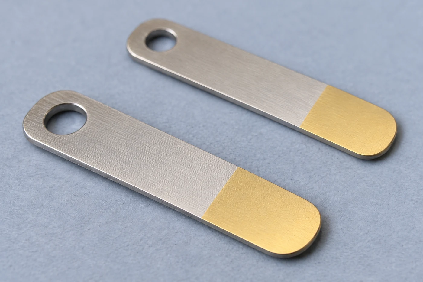
선택 도금된 프레스 단자에서는 도금 영역의 위치도 하나의 기능 치수입니다. 접촉점이 도금 경계에 걸리거나 굽힘·조립 후 위치가 이동하면, 단자 전체의 두께가 맞아도 의도한 접촉면이 확보되지 않을 수 있습니다. 필요한 면적뿐 아니라 기준 홀이나 외형에서 경계까지의 위치 허용범위를 함께 전달하는 것이 유용합니다.
아래 사진의 단자 형상은 접촉 영역과 몸체를 구분하는 예시입니다. 표면의 색상 차이로 특정 금속의 종류나 두께를 판정할 수는 없습니다. 실제 도면에는 기능면의 소재·층 구성·두께·위치와 최종 검사 조건을 별도로 지정하고, 외관 사진은 형상과 배치 설명에 활용하는 것이 적절합니다.
05두께 분포와 선택 관리
전해·무전해 도금의 두께 분포
도금 시간과 평균 두께가 같아도 모든 위치에 같은 양이 쌓이는 것은 아닙니다. 전해 도금에서는 부품 형상과 양극의 위치, 랙에 놓인 방향에 따라 전류 분포가 달라집니다. 돌출부와 양극을 향한 영역은 두꺼워지고, 오목하거나 가려진 영역은 얇아지는 경향을 고려해야 합니다.
이 차이는 치수 한계와 최소 피막 요구를 동시에 어렵게 만들 수 있습니다. 홀 안쪽의 최소 두께를 맞추려고 도금을 늘리는 동안 입구나 외부 돌출부의 최대 치수가 먼저 한계를 넘을 수 있기 때문입니다. 전체 평균값을 올리는 대응보다 문제가 되는 위치의 분포를 바꾸는 접근이 필요한 경우입니다.
균일성의 조건
무전해 도금은 외부 전류 분포에 의존하지 않는 화학 반응으로 피막을 형성하므로 복잡한 형상에서 균일한 두께를 얻는 데 유리할 수 있습니다. 그러나 “무전해이므로 모든 내부면이 같은 두께”라고 정할 수는 없습니다. 반응이 진행되는 표면의 활성과 새로운 용액의 공급, 반응 부산물의 배출이 확보되어야 합니다.
막힌 홀이나 깊은 홈에서는 용액 교환이 어렵거나 발생한 기체가 머물 수 있습니다. 부품 방향과 교반은 이런 영향을 줄이기 위한 변수이며, 교반이 강할수록 언제나 좋은 것도 아닙니다. 실제 형상에서 용액 접근성과 기체 배출을 확인하고 필요한 위치의 두께를 측정해야 균일성에 대한 판단이 가능합니다.
| 방식·영역 | 두께 분포의 주요 변수 | 설계 검토 방향 |
|---|---|---|
| 전해 도금 외부면 | 전류 분포·양극 거리·부품 배치 | 돌출부 최대 두께와 치수 확인 |
| 전해 도금 내부면 | 가림·전류 접근·형상 | 내부 최소 두께와 입구 성장 동시 확인 |
| 무전해 도금 | 표면 활성·용액 교환·반응 조건 | 복잡한 면의 실제 피복 상태 확인 |
| 깊은 홀·홈 | 용액 유입·교환·기체 배출 | 방향·취급·국부 검사 위치 협의 |
공정 이름만으로 치수 공차를 확정하기보다 시험 가공품에서 위치별 분포를 먼저 확인하는 편이 합리적입니다. 같은 도금 종류라도 소재와 전처리, 형상, 투입 방식이 바뀌면 기존 분포를 그대로 기대하기 어렵습니다. 필요한 기능면의 최소·최대 두께와 최종 치수가 함께 만족되는지로 공정 적합성을 판단해야 합니다.
랙·마스킹과 국부 관리
도금 여유를 설계하는 방법은 가공 치수를 바꾸는 것에 한정되지 않습니다. 어느 면을 도금하고 어느 면을 유지할지 정하거나, 부품을 거는 방향과 전류가 접근하는 조건을 조절하는 것도 방법입니다. 다만 형상이나 공정 선택을 바꾸면 품질 확인 위치도 함께 조정해야 합니다.
전해 도금에서는 랙 배치, 양극 위치, 차폐물과 보조 양극 등을 활용해 두께 분포를 조절할 수 있습니다. 부품끼리의 가림이나 전기적 접촉 상태까지 포함해 실제 적재 조건을 검토해야 합니다. 한 개의 시험품에서 확인한 결과를 밀집된 양산 랙에 그대로 적용하면 분포가 달라질 수 있습니다.
| 관리 수단 | 기대하는 역할 | 동시에 정할 사항 |
|---|---|---|
| 랙 방향·간격 | 접근 조건과 부품 간 가림 조절 | 접점 위치·적재 조건·재현성 |
| 차폐·보조 양극 | 전해 도금의 국부 분포 조절 | 대상 영역·치수 상한·최소 피막 |
| 기능 홀 마스킹 | 해당 내경의 도금 성장 억제 | 밀봉 상태·경계·잔류물·최종 검사 |
| 선택 도금 경계 | 필요한 영역에 기능층 확보 | 기준 위치·경계 허용범위·전이부 |
비도금 영역의 기능 유지
기능 홀을 마스킹하면 내경 성장 계산에서 해당 면의 피막을 제외할 수 있지만, 실제 마스킹이 완전하다는 확인이 필요합니다. 경계의 누설이나 들뜸, 제거 후 잔류물은 치수와 조립에 영향을 줄 수 있습니다. 마스킹 표시에는 시작·끝 위치와 경계 허용범위, 도금 후 확인할 면을 포함하는 것이 좋습니다.
랙 접촉 부위도 도면 검토에서 빠뜨리지 않아야 합니다. 접촉 자국이나 국부 비도금이 허용되는 곳을 기능면 밖으로 정할 수 있는지 검토하고, 허용 위치가 없다면 다른 고정 방법을 협의해야 합니다. 외관면과 기능면의 중요도를 구분하면 필요한 성능을 지키면서 작업 방법을 구체화할 수 있습니다.
아래 3D는 균일 피막, 국부적으로 다른 두께, 기능 홀 마스킹을 비교합니다. 국부 분포는 차이를 설명하기 위한 정성적 형상이며 전류 해석이나 실제 두께 측정 결과가 아닙니다. 마스킹 장면은 이상적으로 도금이 제외된 상태를 나타내므로 실제 적용에서는 경계와 누설을 별도로 검증해야 합니다.
국부 두께 분포와 마스킹
INTERACTIVE 3D모서리와 입구의 성장, 오목한 내벽의 얇은 층을 정성적으로 강조했습니다. 전류 밀도·유동·실측 두께를 계산한 결과가 아니며 실제 분포는 공정·형상별로 검증합니다.
06검사와 제작 승인
피막 두께와 완성 치수의 검사
피막 두께 검사와 완성 치수 검사는 서로 다른 질문에 답합니다. 두께 측정은 필요한 층이 지정 위치에 형성되었는지 확인하고, 치수 측정은 최종 외형이 조립 요구를 만족하는지 확인합니다. 한쪽 성적서가 다른 쪽을 대신하지 못하며, 실제 불량을 설명하려면 두 기록을 같은 부품과 위치에 연결해야 합니다.
XRF는 금속 피막을 비파괴로 평가하는 데 활용되지만 모든 면을 직접 길이로 읽는 장비는 아닙니다. 측정한 단위 면적당 코팅 질량을 두께로 환산할 때에는 밀도 정보가 필요합니다. 다층 조합과 성분, 교정 표준, 측정점의 크기와 위치가 맞지 않으면 숫자를 얻더라도 해석이 달라질 수 있습니다.
측정 위치와 불확도
작은 핀이나 곡면에서는 조사 영역이 목표 면 안에 들어가는지, 시료의 높이와 자세가 적절한지 확인해야 합니다. 평탄한 외부면의 XRF 결과 하나를 좁은 홀 내부의 두께로 대체할 수는 없습니다. 측정 접근성이 부족한 면은 적절한 시험편이나 단면 검사 등 다른 확인 방법을 실제 부품과의 관계를 정한 뒤 활용해야 합니다.
| 검사 방법 | 주요 확인 대상 | 해석의 한계 |
|---|---|---|
| XRF | 지정 위치의 금속 피막·층 구성 | 밀도·조성·교정·측정점·형상 영향 |
| 광학 단면 검사 | 절단 위치의 국부 피막 두께 | 시편 준비·절단 방향·관찰 위치 영향 |
| 외경·내경 측정 | 완성품의 실제 크기 | 측정력·온도·방향·형상 영향 |
| 기능 게이지·조립 확인 | 지정 조건의 끼워맞춤 | 피막 두께와 원인 분석을 대신하지 않음 |
광학 단면 검사는 원하는 위치의 층을 직접 관찰하는 데 유용하지만 절단과 연마 상태가 결과에 영향을 줍니다. 가장자리 둥글어짐이나 비스듬한 단면을 실제 피막 두께로 읽지 않도록 시편 준비와 관찰 방법을 정해야 합니다. ASTM B487은 단면 광학 측정, ASTM B568은 X선 기반 피막 측정을 다루며 실제 적용 절차는 계약에서 정한 판본과 조건에 따라 확인합니다.
치수 장비의 표시 분해능 0.001 mm는 측정 불확도가 1 μm라는 뜻이 아닙니다. 측정력과 접촉면, 교정 상태, 반복성, 부품 온도까지 포함해 판정에 필요한 능력을 검토해야 합니다. 정밀 길이 측정의 기준 온도인 20 °C와 실제 측정 온도의 차이를 고려하고, 허용 한계에 가까운 결과는 합의한 불확도와 판정 규칙으로 다루는 것이 좋습니다.
도면·발주와 승인 기준
도금 여유가 잘 설계된 도면은 도금 업체가 알아서 맞추어야 할 빈칸을 줄입니다. 최종 기능 치수와 도금 전 치수, 층 구성과 위치별 두께를 함께 제시하고 어느 항목이 최종 합격 기준인지 구분합니다. 도금 종류의 명칭만 지정하는 것보다 생산과 검사에서 같은 판단을 내리기 쉽습니다.
발주 자료에는 바탕 재료와 열처리 상태, 도면 개정, 수량, 상대 부품과 조립 조건도 포함하는 것이 좋습니다. 같은 외형이라도 접촉부인지 안내부인지에 따라 중요한 면과 검사 방법이 달라집니다. 고강도 소재처럼 별도 후처리 관리가 필요한 경우에는 적용 규격과 승인 공정을 함께 정하고 임의의 공정 생략으로 치수만 맞추지 않아야 합니다.
가공·도금·조립의 검사 연결
| 단계 | 기록할 핵심 내용 | 다음 단계로 전달할 기준 |
|---|---|---|
| 도면 검토 | 최종 치수·층별 두께·기능면·비도금 영역 | 같은 개정과 단위의 승인 도면 |
| 도금 전 검사 | 가공 치수·형상·버·전처리 기준 상태 | 도금 여유를 포함한 투입 가능 여부 |
| 도금 후 검사 | 국부 피막·완성 치수·외관·경계 | 피막과 치수의 동시 합격 |
| 최종 승인 | 상대 부품과의 조립·요구 기능 | 실제 공급 상태와 변경 관리 기준 |
초도품에서는 완성 치수만 보관하지 말고 도금 전후의 같은 위치를 비교할 수 있는 기록을 남기는 편이 좋습니다. 차이가 예상보다 크면 바탕 제거, 피막 분포, 변형, 측정 조건 중 어느 부분에서 달라졌는지 확인할 수 있습니다. 측정 위치와 방법이 다르면 전후 수치의 차이를 곧바로 피막 두께로 해석하기 어렵습니다.
양산 승인 뒤에도 랙 배치나 공정 경로, 하도금 조합, 마스킹 방법이 바뀌면 치수 영향의 재확인이 필요합니다. 승인된 시험품과 다른 조건에서 생산하면서 예전 두께 성적서만 재사용하면 기능면의 분포 변화를 놓칠 수 있습니다. 변경이 영향을 주는 면을 중심으로 치수와 피막 검사 범위를 정하면 검증도 구체적입니다.
제작 검토에서 먼저 답해야 할 질문은 “몇 μm를 도금할 것인가”와 “도금이 끝난 뒤 어디가 어떤 치수여야 하는가”입니다. 두 요구가 함께 정해져야 가공 여유와 공정 분포, 검사 방법을 일관되게 연결할 수 있습니다. 아이디메탈에 부품 제작을 문의할 때에도 동일 개정의 도면과 기능면 표시, 도금 사양, 최종 검사 요구를 함께 전달하면 검토 기준을 명확히 할 수 있습니다.
English Edition · Dimensions Change After Plating: Coating Allowance Design for Precision Metal Parts
A shaft and bore that fit after machining may no longer assemble after plating: the shaft grows while the bore shrinks. Coating allowance design defines how a layer measured in micrometres affects final dimensions and fits, and allocates tolerances between machining and coating.
Small pins and bushings, stamped terminals and threaded parts require a distinction between per-side thickness and diametral change, and between multilayer buildup and local distribution. Achieving both finished dimensions and the required surface function connects the drawing reference state to inspection before and after plating under consistent conditions.
Per-side thickness and diameter
Distinguish μm and μin, two-sided buildup and multilayer sums.
Machining tolerances and assembly
Derive pre-plating dimensions and check worst-case fits.
Distribution and acceptance
Connect local thickness, masking, XRF, sections and size inspection to the drawing.
01Dimensional references and units
Dimensional references before and after plating
When a precision shaft passes machining inspection but will not enter its bushing after plating, first check which process state the drawing dimensions describe. The machined diameter and the finished, plated diameter are different quantities. Even a thin metallic layer can consume the required assembly allowance when it builds on two opposing surfaces.
Coating allowance design starts with the final functional dimensions and allocates the available range between machining and finishing. Treating it as a late subtraction of coating thickness can produce a dimensionally acceptable part with insufficient coating on a functional surface, or adequate coating on a part that is difficult to assemble.
Process state and functional surfaces
It is useful to distinguish the raw, machined, plated and subsequently finished states on the drawing. Where grinding or lapping follows plating, the as-plated size may differ from the delivery size. Defining both the dimensional acceptance stage and the coating inspection stage makes the corresponding reports comparable.
| Item | Drawing requirement | Practical meaning |
|---|---|---|
| Final functional size | Delivery state or completion of specified finishing | Acceptance for assembly and location |
| Pre-plating size | Substrate size immediately before the specified operation | Control between machining and plating |
| Coating thickness | Range for each layer and measurement location | Shared input for function and dimensional buildup |
| Uncoated areas | Functional faces, boundaries and permitted contact marks | Basis for masking and racking |
Not every surface needs the same priority. Identify the surfaces that directly provide function—such as a guide shaft, locating bore, electrical contact face or fastening thread—and distinguish them from appearance surfaces. Linking size, coating, form and inspection locations to these functional surfaces also clarifies the information needed by production staff.
A part’s coating allowance also depends on its mating component and assembly sequence. The required finished condition changes if the mating bore is coated, if assembly uses a press, or if the pair must slide freely. Reviewing only the detail drawing can therefore leave a gap between individual acceptance and actual assembly requirements.
Micrometres, microinches and per-side thickness
Numbers in coating specifications cannot be compared without checking their units. One micrometre is 0.001 mm, while one microinch is 0.0254 μm. Accordingly, 100 μin equals 2.54 μm and 200 μin equals 5.08 μm. Confusing μm with μin changes the interpretation dramatically even when the numerical value is the same.
The unit mil in inch-based documentation requires separate attention. One mil is 0.001 in, or 25.4 μm; it is not a microinch. When transferring an overseas drawing, retain the original unit together with its conversion and avoid premature rounding during calculations.
| Notation | Exact conversion | Interpretation |
|---|---|---|
| 1 μm | 0.001 mm | Length expressed in micrometres |
| 1 μin | 0.0254 μm | One microinch |
| 1 mil | 25.4 μm | A separate name for 0.001 in |
| 200 μin | 5.08 μm | Not exactly equal to 5 μm |
Surface thickness and diametral buildup
Coating thickness ordinarily describes the distance normal to the substrate at one surface. A uniform 5 μm deposit on a cylindrical surface increases its radius by 5 μm and its diameter by 10 μm. Do not assume that “10 μm plating” means either per-side thickness or diametral buildup without checking the drawing definition.
If the thicknesses on opposing surfaces differ, the increase along that diameter is the sum of the two local values. Twice a reported average is not necessarily the actual dimensional increase at a specific location. The calculation must also distinguish a specified minimum, average or nominal thickness.
The thickness used in a dimensional calculation must be controlled on the relevant functional surface. Applying a value measured on a flat appearance surface directly to a deep bore or thread root can overlook the real distribution. The numerical examples here are assumptions for explaining the calculations; the photographs are generated editorial illustrations of geometry, not records of delivered coatings or inspection results.
02Coating buildup and geometry
Multilayer coatings and changes through processing
A thin outer layer does not necessarily mean a small total dimensional change. When an underplate and functional finish are deposited in sequence, add the thicknesses of every layer retained on that surface. Calculating from appearance or the outer-layer name alone can omit the allowance consumed by the underplate.
For illustration, assume that a 3 μm nickel layer and a 5 μm tin layer remain uniformly on the same cylindrical surface. Their total per-side thickness is 8 μm and the diameter increases by 16 μm. These values are not a recommended product specification; the actual stack depends on substrate material, contact, corrosion and soldering requirements, and subsequent processing.
Added layers and removed metal
Simple layer addition assumes that no substrate removal or shape change occurs between the compared states. Pickling, etching or polishing can remove metal, while post-plating grinding or lapping removes part of the deposited layer. The name “cleaning” alone does not establish that dimensions are unaffected; the actual chemistry and operating conditions matter.
| Process element | Treatment in the calculation | State to verify |
|---|---|---|
| Underplate and topcoat | Sum of the layers retained on the same surface | Layer limits and final retained thickness |
| Pretreatment removal | Account for removal separately from buildup | Dimensions and surfaces before and after removal |
| Post-plating grinding or lapping | Account for the coating removed | Finished size and remaining functional layer |
| Heat treatment or straightening | Review separately from layer addition | Final form, material condition and process sequence |
If r is the material removed per side and t is the total retained deposit, the ideal net diameter change is 2(t−r). Predicting a small net increase from this expression is unreliable when neither removal nor deposition is controlled. Where two larger changes offset each other, variation in either remains in the final dimension.
A plan to recover dimensions by finishing must also preserve the coating’s function. Preferential removal at high spots can leave a local layer too thin even when the average seems adequate. Including both final size and retained coating thickness in acceptance helps prevent dimensional correction from sacrificing surface function.
Outside diameters, bores and two-sided buildup
A cylindrical shaft becomes larger as metal is added to its outside surface. A bore becomes smaller as the deposit grows inward from its walls. The same per-side thickness therefore changes these dimensions in opposite directions; copying the outside-diameter correction sign to a bore gives the wrong machining allowance.
For pre-plating outside diameter D, bore diameter H and uniform per-side thickness t on the relevant surface, the final values are D+2t and H−2t. If D and H are in millimetres, convert t to millimetres as well. A thickness of 10 μm is 0.010 mm, giving a diametral change of 0.020 mm.
| Geometry and assumption | Dimensional change | Illustrative calculation |
|---|---|---|
| Cylindrical outside surface, t per side | Outside diameter +2t | 10.000 mm + 2×0.010 mm = 10.020 mm |
| Bore walls, t per side | Bore diameter −2t | 10.040 mm − 2×0.010 mm = 10.020 mm |
| Flat plate, t on each face | Overall thickness +2t | 0.500 mm + 2×0.005 mm = 0.510 mm |
| Coating on one face only | That surface moves by t | Apply according to the datum and measurement direction |
Local thickness and actual geometry
These are geometric relations for straight cylinders, uniform deposits and no pretreatment removal or deformation. A tapered shaft or a coating buildup at a bore entrance can make one cross-sectional diameter insufficient to predict passage through the full length. Equal coating thickness does not make different starting geometries equivalent.
Internal slots and spaces between faces are calculated from the coatings on the opposing walls. If their thicknesses are t₁ and t₂, the gap decreases by t₁+t₂. Centre distances and datum-based positions depend on what is measured and which reference is used, so a universal addition or subtraction of 2t is inappropriate.
The following 3D view compares outside-diameter growth and bore reduction using coating thickness controls in the same unit. The displayed layer is visually enlarged for readability, while the numerical dimensions follow the actual unit conversion and two-sided buildup equations. Its apparent thickness ratio should not be interpreted as a real product cross-section.
One-side thickness and diameter changes
INTERACTIVE 3DDafter = D + 2t · Hafter = H − 2t
Assume a uniform one-side thickness t on the cylindrical functional surfaces. The shaft grows on both sides while the bore closes from both sides. End faces, pretreatment removal and later machining are excluded.
03Tolerance allocation and fits
Machining allowance derived from final tolerances
Shifting the machining target by the average coating buildup may be insufficient to guarantee the finished size. Coating thickness has lower and upper limits, just as machining does. If every allowed combination must remain within the finished specification, evaluate the adverse limits of both processes together.
For an outside diameter, the smallest substrate plus the minimum buildup must meet the finished lower limit. The largest substrate plus the maximum buildup must not exceed the upper limit. Thus the permitted pre-plating range extends from the final lower limit minus 2tmin to the final upper limit minus 2tmax.
| Illustrative outside-diameter condition | Value | Check |
|---|---|---|
| Permitted final diameter | 10.000–10.020 mm | Total tolerance width 20 μm |
| Per-side coating range | 5–10 μm | Diametral buildup 10–20 μm |
| Permitted pre-plating diameter | 9.990–10.000 mm | 10 μm remains for machining variation |
| Lower and upper combinations | 9.990+0.010 / 10.000+0.020 | 10.000 / 10.020 mm |
Allocating the tolerance width
The table uses a conservative guarantee in which size and thickness may independently occupy any point within their permitted ranges. Subtracting 2×(maximum minus minimum per-side thickness) from the final tolerance width gives the range left for machining. A negative result means that shifting the machining target alone cannot guarantee every combination.
Treating a negative allowance only as a machining-accuracy problem makes resolution difficult. Options include reconsidering the final tolerance without compromising function, narrowing the coating range, or reviewing selective plating, masking or subsequent finishing. None is automatically correct; the minimum functional coating and demonstrated process capability must both be considered.
For a bore, both the sign and the positions of the minimum and maximum coating thickness change. Its pre-plating lower limit is the final lower limit plus 2tmax, and its upper limit is the final upper limit plus 2tmin. Instead of recording a single “target plus coating” value, retain separate checked calculations for outside diameters and bores.
Shaft–bore assembly and worst-case conditions
When both bore and shaft are coated, both parts contribute to the dimensional change. The bore shrinks and the shaft grows, so the diametral clearance is the initial clearance minus 2×(per-side bore thickness + per-side shaft thickness). Accounting for only one coating overestimates the available assembly clearance.
Diametral clearance must also be distinguished from a one-sided radial gap. In an ideal concentric assembly, a 20 μm diametral clearance gives a 10 μm gap on each side. If gravity or load brings the shaft against one side, the two gaps differ; a visible one-sided gap cannot simply be read as the diameter difference.
| Illustrative condition | Before plating | Possible range after plating |
|---|---|---|
| Bore diameter | 10.030–10.050 mm | 10.010–10.040 mm |
| Shaft diameter | 9.990–10.000 mm | 10.000–10.020 mm |
| Per-side thickness on each part | Bore and shaft each 5–10 μm | Uniform deposits and no additional removal assumed |
| Diametral clearance | 30–60 μm | −10–40 μm |
Combinations that compromise assembly
The smallest finished bore is 10.030−0.020=10.010 mm, while the largest finished shaft is 10.000+0.020=10.020 mm. Their combination gives −0.010 mm clearance, equivalent to 10 μm diametral interference. At the opposite limits, 10.040−10.000=0.040 mm leaves 40 μm of clearance.
Every pre-plating combination in this example has positive clearance, yet after plating the allowed range includes both interference and clearance. This is why successful assembly of one average-sized prototype does not establish assembly across the entire range. If selective assembly or size-dependent process adjustment is used, its control method must form part of the supply agreement.
The model below starts with a 40 μm diametral clearance and 5 μm per-side coatings on both the bore and shaft, leaving 20 μm after plating. This is one combination, separate from the interval calculation in the table. Zero clearance provides no positive allowance, while a negative value indicates geometric interference; the model therefore does not show free passage in those states.
Mating-part coatings and assembly clearance
INTERACTIVE 3DCafter = Cbefore − 2(ts + th)
Shaft and bore coating thicknesses are independent. At 5 μm each, diametral clearance is 40 − 2(5 + 5) = 20 μm. Teal is an explanatory highlight of positive clearance.
04Threads and functional surfaces
Thread pitch diameter and coating allowance
Thread allowance cannot be evaluated using only the 2t relationship for a cylindrical diameter. Deposit on the inclined flanks has a larger effect on the pitch diameter that governs engagement. A major diameter within its limits does not ensure correct engagement with a standard gauge or mating thread when pitch diameter or thread form is unsuitable.
For an ideal symmetric 60° thread with a uniform thickness t deposited normal to both flanks, the magnitude of the pitch-diameter change is approximately 4t. External-thread pitch diameter increases and internal-thread pitch diameter decreases. For example, a 5 μm coating normal to the flanks corresponds to approximately 20 μm of pitch-diameter change.
Applicability to individual thread dimensions
The factor 4t must not be applied to every thread dimension. It describes pitch diameter; changes at crests and roots require separate review of their local coating thickness and geometry. Do not transfer the same factor directly to other flank angles or nonuniform coatings without checking the relevant thread form and specification.
| Control item | Coating effect | Inspection connection |
|---|---|---|
| 60° external-thread pitch diameter | Approximately +4t for ideal uniform deposition | Pre-plating allowance and final thread class |
| 60° internal-thread pitch diameter | Approximately −4t for ideal uniform deposition | Internal coating distribution and final engagement |
| Crests and roots | Separate changes set by local thickness and form | Major/minor diameters and profile requirements |
| Deep internal threads | Coating may vary with position | Thickness on an accessible face is not a substitute |
Pre-plating and post-plating thread gauges verify different states. Machining controls the specified dimensions with allowance, while final inspection checks the delivery thread class and function. Reusing a pre-plating gauge for final acceptance, or relying only on a final gauge to identify whether machining or coating caused a problem, leaves important control information missing.
Running a tap through the coated thread simply to recover engagement also requires prior review. Removing coating from the flanks can change the required corrosion protection or friction condition. The drawing or approved process should state whether chasing, additional cutting or lubrication is permitted and how the resulting condition is inspected.
Contact faces, fits and geometric accuracy
A correct plated diameter does not by itself establish that the component performs its function. Guide components require suitable motion and positional repeatability, while electrical contact components depend on contact force and surface condition. Review final size together with function-related form requirements such as cylindricity, parallelism and contact location.
A coating does not automatically erase machining features. Remaining burrs, dents or raised edges can still create local interference or uneven contact after plating. Controlling the pre-plating surface, including entrance chamfers and sharp edges, helps reduce recurring defects attributed to the finishing stage.
| Functional surface | Review beyond size | Oversimplified judgment to avoid |
|---|---|---|
| Guide shaft and bushing | Cylindricity, straightness, surface and working load | Assuming one accepted diameter guarantees motion |
| Press-fit or locating feature | Interference range, edges and coating damage | Treating all deposit as effective interference |
| Electrical contact face | Contact force, mate, contact location and retained coating | Judging electrical performance by color or thickness alone |
| Planar datum surface | Flatness, parallelism and selective-coating boundary | Judging the datum solely from average local thickness |
Balancing surface function and dimensional correction
An electrical contact needs the required layer at the location where contact actually occurs. Cutting or forcing the surface to recover assembly can change that layer and its surface condition. Verify that dimensional correction does not compromise contact function, considering the mating component and assembly conditions.
For a selectively plated stamped terminal, the location of the coated zone is itself a functional dimension. If contact falls on the boundary or shifts after forming and assembly, correct overall thickness may still leave the intended contact area unavailable. Specify the positional tolerance of the boundary from locating holes or edges as well as the required area.
The terminal photograph in this article illustrates the distinction between the contact region and the body. Color differences do not identify a particular metal or coating thickness. Actual drawings should separately specify the material, layer stack, thickness, location and final inspection conditions; photographs are appropriate for explaining shape and arrangement.
05Thickness distribution and selective control
Thickness distribution in electroplating and electroless plating
Equal plating time and average thickness do not mean equal buildup everywhere. In electroplating, part geometry, anode placement and orientation on the rack affect current distribution. Projections and regions facing the anode tend to receive more deposit, while recessed or shielded areas may receive less.
This distribution can make dimensional limits and minimum coating requirements difficult to satisfy simultaneously. Increasing deposition to reach the minimum inside a bore may drive the entrance or an external projection beyond its maximum size first. Such cases may require changing the local distribution rather than raising the overall average.
Conditions for uniformity
Electroless deposition forms the coating chemically without relying on an externally imposed current distribution, which can favor uniform thickness on complex shapes. It does not follow that every internal surface will have the same thickness. Surface activity, supply of fresh solution and removal of reaction products must be maintained.
Blind holes and deep recesses may restrict solution exchange or retain evolved gas. Orientation and agitation are variables for managing these effects, but stronger agitation is not always better. Assess uniformity by checking solution access and gas release in the actual geometry and measuring the required locations.
| Process or region | Key distribution variables | Design review direction |
|---|---|---|
| Electroplated external surfaces | Current distribution, anode distance and part layout | Check maximum buildup and size at projections |
| Electroplated internal surfaces | Shielding, current access and geometry | Check internal minimum thickness and entrance buildup together |
| Electroless deposition | Surface activity, solution exchange and reaction conditions | Verify actual coverage on complex surfaces |
| Deep holes and recesses | Solution access, exchange and gas escape | Agree orientation, handling and local inspection sites |
Rather than assigning a dimensional tolerance from the process name alone, first examine the positional distribution on trial parts. A change in substrate, pretreatment, geometry or loading method can invalidate an earlier distribution even within the same coating family. Judge suitability by meeting both the local coating limits and the finished dimensions on the required functional surfaces.
Racking, masking and local control
Coating allowance design is not limited to changing machined dimensions. It can also define which surfaces receive coating and which remain unchanged, or adjust hanging orientation and current access. Changes to geometry or process selection should be accompanied by a review of where quality is verified.
Electroplating distribution can be adjusted through racking, anode placement, shields and auxiliary anodes. Review the actual loading arrangement, including mutual shielding and electrical contact. Results from one isolated trial part may not transfer unchanged to a densely loaded production rack.
| Control method | Intended role | Items to define alongside it |
|---|---|---|
| Rack orientation and spacing | Control access and mutual shielding | Contact locations, loading and repeatability |
| Shields and auxiliary anodes | Adjust local electroplating distribution | Target areas, size upper limits and minimum coating |
| Masking a functional bore | Suppress coating buildup in that bore | Seal, boundary, residue and final inspection |
| Selective-coating boundary | Place the functional layer where needed | Reference position, boundary tolerance and transition |
Preserving the function of uncoated areas
Masking a functional bore permits its coating to be excluded from the buildup calculation only when the actual mask is verified. Leakage or lifting at the boundary, and residue after removal, can affect size and assembly. Masking instructions should define the start and end positions, boundary tolerance and surfaces to inspect after plating.
Rack contact locations also belong in the drawing review. Consider whether contact marks or locally uncoated areas can be permitted outside functional surfaces; if no suitable location exists, discuss a different holding method. Separating appearance and functional priorities makes the process more concrete while protecting the required performance.
The following 3D view compares uniform deposition, locally varying thickness and masking of a functional bore. The local distribution is a qualitative illustration, not a current-field simulation or measured thickness map. The masking state idealizes complete exclusion of the deposit; actual implementation requires separate verification of the boundary and leakage.
Local thickness distribution and masking
INTERACTIVE 3DEdge and entrance buildup and a thinner recessed wall are qualitatively emphasized. This is not a current-density, flow or measured-thickness calculation; actual distribution requires geometry- and process-specific verification.
06Inspection and manufacturing approval
Inspection of coating thickness and finished dimensions
Coating and dimensional inspection answer different questions. Thickness measurement checks that the required layer exists at the specified location; dimensional measurement checks whether the finished geometry meets assembly requirements. Neither report replaces the other, and explaining a failure requires linking both records to the same part and location.
XRF can evaluate metallic coatings nondestructively, but it does not directly read a length on every surface. Converting measured coating mass per unit area into thickness requires density information. Layer composition, calibration standards, measurement spot size and location must be appropriate for the resulting number to be interpreted correctly.
Measurement location and uncertainty
On small pins and curved surfaces, check that the irradiated spot lies within the intended area and that sample height and orientation are appropriate. A single XRF reading from a flat exterior is not a substitute for thickness inside a narrow bore. Inaccessible surfaces may require an appropriate witness specimen or cross-section method with an established relationship to the actual part.
| Inspection method | Primary question | Interpretation limit |
|---|---|---|
| XRF | Metallic coating and layer system at a specified location | Density, composition, calibration, spot and geometry |
| Optical cross-section | Local coating thickness at the cut | Specimen preparation, section orientation and location |
| Outside- and inside-diameter measurement | Actual finished size | Measuring force, temperature, orientation and form |
| Functional gauging or assembly check | Fit under specified conditions | Does not replace coating measurement or cause analysis |
Optical cross-sections are useful for observing the layer at a selected location, but cutting and polishing affect the result. Preparation and observation must prevent edge rounding or an oblique section from being mistaken for true thickness. ASTM B487 addresses optical cross-section measurement and ASTM B568 addresses X-ray coating measurement; the applicable procedure must follow the edition and conditions agreed in the contract.
An instrument display resolution of 0.001 mm does not mean a measurement uncertainty of 1 μm. Assess suitability for acceptance using measuring force, contact surfaces, calibration, repeatability and part temperature. Account for differences between actual temperature and the 20 °C reference for precision dimensional measurement, and handle results near limits using the agreed uncertainty and decision rule.
Drawing, purchasing and approval requirements
A well-defined coating allowance reduces the unspecified decisions left to the finishing supplier. Present final functional dimensions, pre-plating dimensions, layer structure and local thickness requirements together, identifying the final acceptance criteria. This gives production and inspection a more consistent basis than naming the coating process alone.
Purchasing information should also include substrate material and heat-treatment condition, drawing revision, quantity, mating component and assembly conditions. Identical shapes can require different critical surfaces and inspections when used as contacts or guides. Where a material requires controlled subsequent treatment, as can occur with high-strength substrates, agree the applicable specification and approved process rather than omitting steps merely to recover dimensions.
Connecting machining, plating and assembly inspection
| Stage | Essential record | Criterion passed to the next stage |
|---|---|---|
| Drawing review | Final size, individual layers, functional and uncoated areas | Approved revision and consistent units |
| Pre-plating inspection | Machined size, form, burrs and pretreatment reference state | Release based on the required coating allowance |
| Post-plating inspection | Local coating, finished size, appearance and boundaries | Concurrent acceptance of coating and dimensions |
| Final approval | Assembly with the mate and required function | Actual supply state and change-control criteria |
For first articles, retain records that compare the same locations before and after plating rather than keeping only finished dimensions. Unexpected differences can then be investigated as substrate removal, coating distribution, deformation or measurement-condition changes. When measurement locations or methods differ, their numerical difference cannot immediately be treated as coating thickness.
After production approval, changes to racking, process route, underplate stack or masking method call for reassessment of dimensional effects. Producing under different conditions while relying on an earlier thickness report can overlook a changed distribution on functional surfaces. Define the dimensional and coating checks around the surfaces affected by the change.
Manufacturing review should first answer both “how many micrometres of coating are required?” and “which surfaces must meet which dimensions after finishing?” Defining both connects machining allowance, process distribution and inspection consistently. When discussing component manufacture with ID METAL, provide the same drawing revision, marked functional surfaces, coating specification and final inspection requirements to establish a clear review basis.
추가 정보
검색엔진용 요약
도금 여유 설계는 편측 피막 두께를 최종 치수와 조립 조건에 반영하고 가공·도금의 공차를 나누는 작업입니다. 단위와 다층 구조, 축·홀·나사의 성장 방향, 국부 분포와 마스킹을 검토하고 피막 두께와 완성 치수를 함께 검사해야 합니다.
핵심 포인트 정리
- 1 μm는 0.001 mm, 1 μin은 0.0254 μm이며 mil과 구분합니다.
- 균일한 편측 피막 t는 원통 외경을 2t 키우고 내경을 2t 줄입니다.
- 하도금을 포함한 잔류 층을 합산하고 전처리 제거와 후가공을 구분합니다.
- 최종 공차에서 피막 두께의 변동분을 반영해 도금 전 치수를 역산합니다.
- 홀과 축을 모두 도금하면 양쪽 피막이 지름 틈새를 함께 줄입니다.
- 60° 나사의 약 4t 관계는 이상적인 유효지름 변화에 한정합니다.
- 무전해 도금도 용액 교환·기체 배출·표면 활성에 따라 국부 차이가 생길 수 있습니다.
- XRF·단면의 피막 검사와 최종 치수·조립 검사를 연결합니다.
FAQ
편측 도금 5 μm이면 축 지름은 얼마나 커지나요?
외주에 균일하게 형성되고 금속 제거나 변형이 없다면 지름은 10 μm, 즉 0.010 mm 커집니다. 반지름 증가와 지름 증가를 구분해야 합니다.
100 μin과 100 μm는 같은 두께인가요?
다릅니다. 1 μin은 0.0254 μm이므로 100 μin은 2.54 μm입니다. 도면의 원래 단위와 환산값을 함께 확인해야 합니다.
홀과 축을 모두 도금할 때 틈새는 어떻게 계산하나요?
도금 전 지름 틈새에서 홀과 축의 편측 두께 합을 두 배로 한 값을 뺍니다. 동심 상태에서 한쪽 반경 간격은 양의 지름 틈새의 절반입니다.
피막 평균 두께만 알면 도금 전 치수를 정할 수 있나요?
전체 범위를 보장하려면 해당 기능면의 최소·최대 두께가 필요합니다. 가공 공차와 피막 편차의 끝값을 조합하고, 남는 공차 폭이 실제 가공으로 가능한지 검토해야 합니다.
60° 나사의 도금 영향은 모두 4t인가요?
약 4t는 플랭크에 균일한 수직 두께가 생기는 이상적인 60° 나사의 유효지름 변화입니다. 외경과 골지름 등 모든 치수에 같은 계수를 적용하는 것은 적절하지 않습니다.
무전해 도금이면 깊은 홀도 항상 같은 두께인가요?
그렇지 않습니다. 외부 전류 분포에는 의존하지 않지만 표면 활성, 용액 교환과 기체 배출이 필요합니다. 실제 형상과 위치에서 피막을 확인해야 합니다.
XRF 두께가 합격이면 완성 치수 검사도 생략할 수 있나요?
피막 두께와 완성 치수는 서로 다른 검사 대상입니다. XRF의 국부 측정 결과만으로 홀의 통과성이나 축의 원통도, 조립 여유를 보장할 수 없습니다.
도금 여유 검토에 필요한 자료는 무엇인가요?
동일 개정의 도면, 바탕 재료와 상태, 최종 치수, 층 구성과 위치별 두께, 비도금 영역, 상대 부품과 조립 조건, 검사 요구를 함께 준비하면 검토 기준이 명확해집니다.
관련 주제 확장 설명
공차 누적과 조립 보장
도금 두께를 조립 공차에 포함하면 가공 검사 합격과 완성품 조립 사이의 차이를 수치로 검토할 수 있습니다.
접촉 기능과 선택 도금
프레스 단자의 접촉 영역은 두께뿐 아니라 위치와 경계가 중요하며, 치수 보정 뒤에도 필요한 피막이 남아야 합니다.
국부 검사와 변경 관리
도금 분포와 측정 위치를 함께 기록하면 랙·마스킹·층 구성 변경 때 재확인할 기능면을 구체적으로 정할 수 있습니다.
내부 링크
조립 여유를 검토할 때에는 공차 누적과 조립성을 함께 확인할 수 있습니다. 표면 기능은 전기접점 도금의 선택 기준, 전후 공정의 오염 관리는 정밀 금속부품 세척과 청정도와 연결됩니다.
기능면과 형상의 검토는 전기접점 및 프레스 금속 브라켓 자료를 참고할 수 있습니다. 도면·도금 사양·최종 치수와 검사 요구는 제품문의·개발의뢰로 전달해 주세요.