
퓨즈 클립 제작:
전류를 흘리면서 퓨즈를 붙잡는 프레스 부품
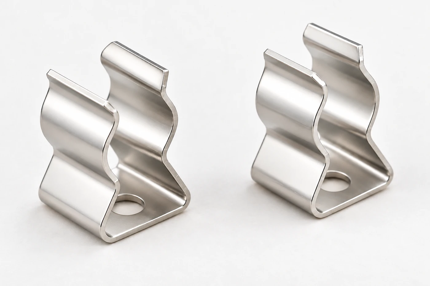
퓨즈 클립은 탄성으로 금속 캡을 잡고 회로의 전류를 퓨즈에 전달합니다. 퓨즈 클립 제작에서는 접촉력·저항·발열과 실장 구조를 함께 설계해, 삽입과 교환 뒤에도 접속 상태가 유지되도록 해야 합니다.
원통형 퓨즈용 프레스 클립의 개발에는 캡과의 접촉 위치, 동합금과 질별, 금형·버·스프링백, 도금과 반복 탈착의 검토가 필요합니다. PCB 및 체결형 조립부터 기능 시험과 양산 승인까지 연결하고, 사진·조작형 3D·계산 예시로 구조와 설계 변수의 영향을 살펴봅니다.
접촉과 탄성
캡의 접촉 위치·힘·삽입 변위를 함께 정의합니다.
소재와 프레스
합금·질별·두께·버·성형·도금을 기능과 연결합니다.
통전과 검증
저항·발열·실장 조건을 조립품에서 확인합니다.
01제품과 접촉 구조
퓨즈 클립과 통전 경로
퓨즈 클립은 퓨즈를 교환할 수 있게 붙잡으면서 회로의 전류를 퓨즈 단자로 전달하는 금속 접촉 부품입니다. 전형적인 원통형 카트리지 퓨즈에서는 양 끝의 금속 캡을 각각 별도의 클립이 잡습니다. 클립은 탄성 구조물이면서 도체이므로, 잘 끼워진다는 외관상의 판단만으로 기능을 확인하기 어렵습니다.
정상적인 전류 경로는 입력 단자 → 첫 번째 클립 → 첫 번째 캡 → 퓨즈 내부의 가용체 → 반대쪽 캡 → 두 번째 클립 → 출력 단자입니다. 양쪽 클립을 금속 바닥판이나 도체로 직접 연결하면 가용체를 우회하는 경로가 생깁니다. 클립의 기계적 지지와 양 끝의 전기적 분리는 조립 구조에서 동시에 성립해야 합니다.
클립·홀더·퓨즈의 역할
| 대상 | 담당하는 기능 | 단독으로 판단할 수 없는 것 |
|---|---|---|
| 퓨즈 클립 | 탄성 유지·금속 캡과의 전기 접촉 | 완제품 절연·접근 보호·회로 차단 성능 |
| 퓨즈 홀더·블록 | 클립 배치·절연 지지·단자 및 보호 구조 | 임의의 퓨즈 조합에서의 사용 적합성 |
| 퓨즈 링크 | 정해진 과전류 조건에서 회로 개방 | 클립의 접촉력·실장부의 온도 |
| 최종 장치 | 배선·방열·절연·교환 접근의 통합 | 부품 외관만으로 전체 정격 확정 |
원통형 퓨즈용 프레스 클립은 금속 캡의 원주면과 맞물리는 구조를 기준으로 검토합니다. 자동차 블레이드 퓨즈의 평판 단자용 클립, 볼트 체결식 퓨즈, 밀폐형 홀더 내부 접점은 접촉 형상과 장착 방식이 다릅니다. 공통 원리는 활용하되, 다른 제품군의 삽입력이나 정격을 그대로 옮겨 사용하지 않습니다.
제작의 핵심은 퓨즈 규격을 베끼는 데 있지 않습니다. 맞물리는 캡의 형상, 사용할 온도와 전류, 교환 횟수, PCB 또는 배선의 연결 방식부터 정리해야 합니다. 이 입력을 소재·금형·도금·검사 항목으로 번역하면 단순한 금속 집게가 아닌 재현 가능한 전기 접속 부품으로 개발할 수 있습니다.
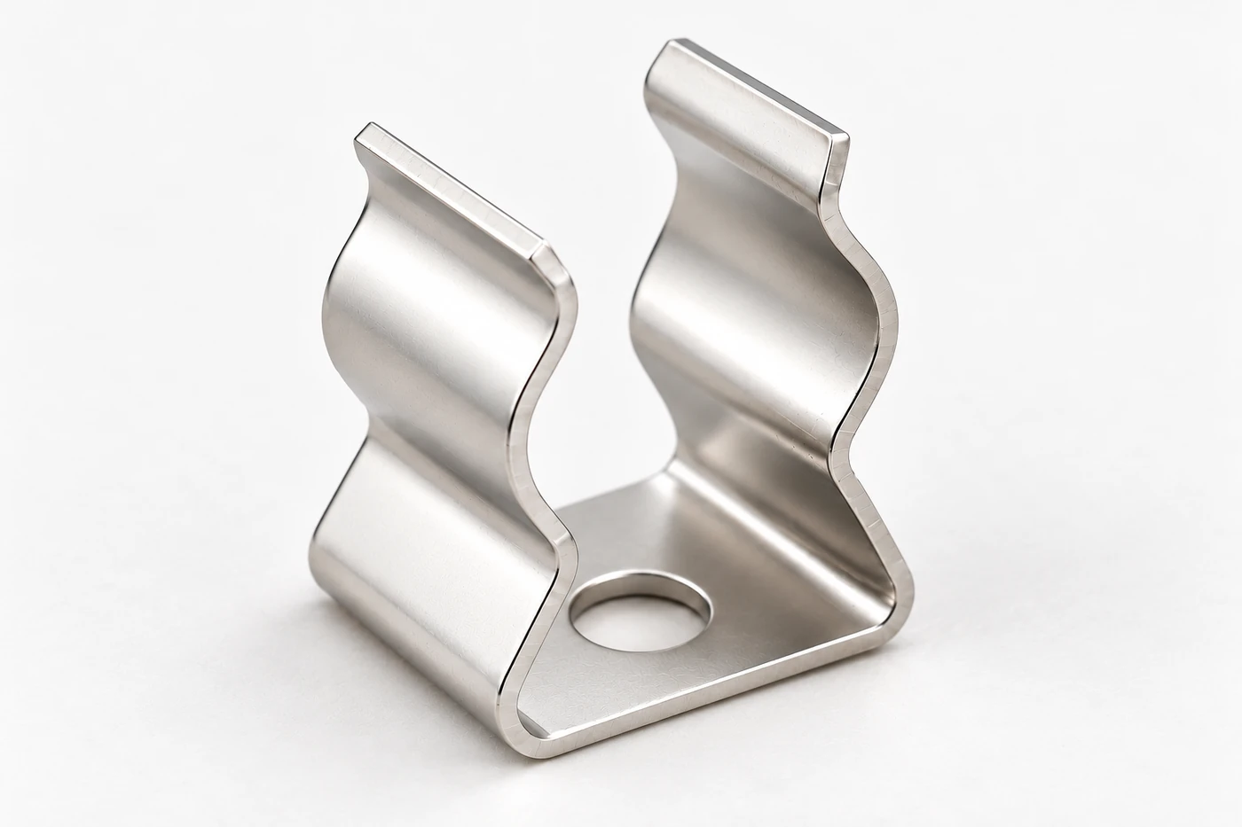
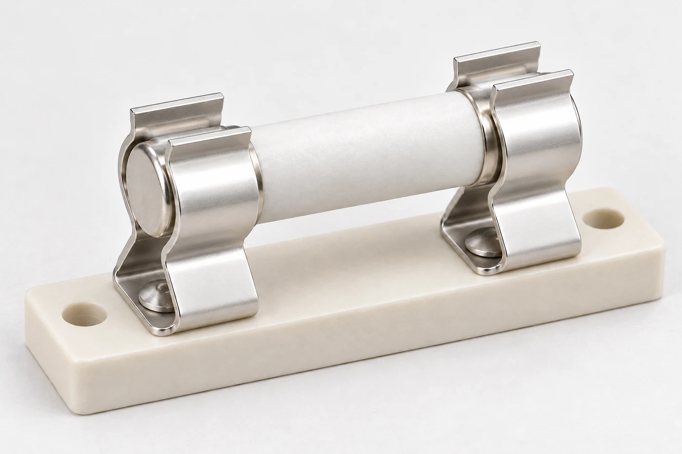
사진은 구조 설명을 위한 생성 이미지이며 특정 납품품이나 설비의 실적 사진이 아닙니다. 조작형 3D와 계산 예시는 삽입 구조·탄성 경향·통전 경로를 설명하는 개념 자료로, 실제 제품 치수·정격 또는 해석 결과를 나타내지 않습니다.
금속 캡과 접촉 구조
클립의 입구, 접촉 곡면, 탄성 팔과 장착 바닥은 서로 다른 역할을 합니다. 입구의 벌어진 부분은 캡을 안내하고, 안쪽 곡면은 최종 안착 위치에서 접촉을 유지합니다. 탄성 팔은 삽입 중 벌어졌다가 캡을 누르는 방향으로 복원됩니다. 장착 바닥은 이 반력을 지지하면서 회로 연결부로 전류를 전달합니다.
접촉 대상은 유리관이나 세라믹 몸통이 아니라 도면으로 정한 금속 캡의 영역입니다. 캡의 끝단 말림, 이음부, 표면 처리와 길이 차이는 실제 접촉 위치를 바꿀 수 있습니다. 같은 외경의 퓨즈라도 클립이 몸통을 누르거나 캡 가장자리만 걸치는 배치라면 정상적인 체결로 간주하기 어렵습니다.
접촉 영역과 위치 제한 구조
| 형상 요소 | 설계 목적 | 검토할 실패 형태 |
|---|---|---|
| 입구 플레어 | 캡 진입 안내·초기 걸림 완화 | 날카로운 끝으로 도금 긁힘·과대 삽입력 |
| 접촉 곡면 | 지정 캡 영역에 반력 전달 | 한쪽 접촉·국부 눌림·접촉 위치 이탈 |
| 끝막이·위치 제한부 | 퓨즈 축 방향 위치 제한 | 캡 간섭·잘못된 방향 조립 |
| 장착부·클립 간격 | 양쪽 캡과 장착 기준 정렬 | 기울어진 안착·몸통 하중·패드 박리 |
눈에 보이는 접촉 면적 전체가 전류를 균일하게 나누어 전달하는 것은 아닙니다. 실제 전류는 표면의 미세 돌기 중 서로 맞닿은 지점을 통해 전달되고 표면막의 영향도 받습니다. 따라서 감싸는 각도나 폭을 크게 만드는 것만으로 접촉저항 감소를 보장할 수 없습니다. 힘의 분포와 표면 상태를 함께 확인해야 합니다.
끝막이는 축 방향 위치를 잡는 기능이고, 캡을 누르는 접촉력과는 별개입니다. 끝막이를 없애거나 위치를 바꾸면 조립 자유도는 늘 수 있지만 캡에 남는 접촉 폭이 달라집니다. 도면에서는 양쪽 클립의 기준 위치와 서로 마주보는 방향을 정하고, 허용되는 퓨즈 길이 범위 전체에서 금속 캡이 충분히 겹치는지 확인합니다.
아래 3D에서는 퓨즈가 내려오면서 두 클립의 입구를 지나 안쪽 접촉 위치에 안착하는 관계를 볼 수 있습니다. 움직임은 형상을 설명하기 위한 것으로 실제 삽입 속도나 힘을 계산하지 않습니다. 캡이 자리 잡은 뒤에는 두 클립이 여전히 서로 전기적으로 분리되어 있고, 전류는 퓨즈 내부를 지나야 한다는 점을 함께 확인할 수 있습니다.
두 개의 독립 클립이 퓨즈를 잡는 구조
INTERACTIVE 3D위치 슬라이더를 움직이면 금속 엔드캡이 입구를 통과하며 양쪽 암이 벌어지고, 안착 후 일부 복원되는 관계를 볼 수 있습니다. 각 클립의 두 암은 하나의 베이스에 이어지지만, 좌우 클립은 서로 분리된 전극입니다. 변형은 간섭을 피하도록 만든 설명용 형상 변화이며 삽입력·접촉력·응력 또는 실제 변형 해석을 계산하지 않습니다.
02소재와 프레스 공정
동합금과 질별 선택
퓨즈 클립의 소재는 전기가 잘 통한다는 이유만으로 정할 수 없습니다. 캡을 잡는 탄성, 성형 중 균열 여유, 사용 온도에서 힘을 유지하는 능력이 함께 필요합니다. 상용 제품에는 스프링 황동, 인청동, 베릴륨동 및 다른 고성능 동합금이 사용되며 각 제품의 소재와 정격은 해당 구조와 시험 조건에 연결되어 있습니다.
소재명 다음에는 정확한 합금 등급과 질별을 지정해야 합니다. 같은 황동이나 인청동도 냉간가공 상태에 따라 항복 특성과 성형 여유가 달라집니다. 높은 강도는 더 큰 탄성 응력을 활용하는 데 도움이 될 수 있지만 좁은 반경으로 굽히기 쉬워진다는 뜻은 아닙니다. 공급 상태와 필요한 후열처리도 소재 선정 단계에서 정리합니다.
접촉력의 장기 유지
| 검토 항목 | 공정·사용 조건과의 연결 | 확인 자료 |
|---|---|---|
| 전기전도도 | 클립 몸체의 저항·발열 | 정확한 합금·질별의 물성 |
| 항복 특성·성형성 | 삽입 변위와 프레스 굽힘 | 재료 규격·방향별 굽힘 자료 |
| 응력 완화 저항 | 온도·시간에 따른 접촉력 유지 | 해당 온도·응력 조건의 데이터 |
| 두께·압연 방향 | 힘의 편차·굽힘 균열 | 코일 성적서·방향·두께 관리 |
응력 완화는 퓨즈가 끼워진 변위를 유지하는 동안 시간이 지나며 누르는 힘이 줄어드는 현상입니다. 처음에는 잘 잡던 클립도 열에 장시간 노출된 뒤 접촉력이 달라질 수 있습니다. 이를 반복 탈착 때문에 생기는 피로와 구분해야 합니다. 장기 장착 제품은 온도·시간을, 자주 교환하는 제품은 반복 변형도 함께 평가합니다.
재료의 최소 굽힘 반경은 절대적인 보증값이 아니라 정해진 시험 조건에서 얻은 참고 기준입니다. 압연 방향에 대한 굽힘 방향, 절단 가장자리와 실제 클립의 복합 곡률을 함께 확인합니다. 금형 배치를 바꾸거나 코일 폭을 최적화해 소재 방향이 달라졌다면 같은 합금이라는 이유로 기존 성형 결과를 그대로 적용하지 않습니다.
초기 검토에서는 도전율이 높은 재료와 강도가 높은 재료를 일렬로 순위 매기기보다 같은 장착 조건에서 비교하는 편이 유용합니다. 최종 간격, 삽입 후 영구 변형, 가열 유지 뒤 힘, 저항 변화를 같은 기준으로 측정합니다. 이렇게 해야 재료 변경의 이점과 추가 성형·열처리·표면처리 비용을 함께 판단할 수 있습니다.
프레스 성형과 공정 관리
프레스 퓨즈 클립의 제조는 외형 타발, 구멍과 단자부 가공, 접촉 곡면 성형, 입구 벌림과 최종 형상 보정으로 나누어 검토할 수 있습니다. 실제 순서는 부품 형상과 수량, 선도금 여부에 따라 달라집니다. 연속 금형은 여러 공정을 이송 피치 안에서 연결하지만 모든 공정을 한 번의 급격한 굽힘으로 끝내는 구조는 아닙니다.
캐리어와 파일럿은 각 공정에서 부품 위치를 유지하고 성형 반력을 지지합니다. 나중에 절단할 연결부를 접촉면 한가운데 두면 절단 흔적이 남거나 후처리가 어려워질 수 있습니다. 이송 안정성뿐 아니라 최종 절단 위치, 배출 중 변형과 후속 도금 방식까지 고려해 스트립 레이아웃을 정합니다.
공정별 품질 기준
| 단계 | 관리 대상 | 다음 공정에 미치는 영향 |
|---|---|---|
| 타발·피어싱 | 절단면·버 방향·파일럿 위치 | 도금 손상·성형 균열·위치 편차 |
| 예비·최종 성형 | 반경·대칭·금형 지지 | 접촉 위치·삽입력·영구 변형 |
| 취출·분리 | 벌어짐·비틀림·절단 잔여부 | 자유 상태 간격·장착 평면 |
| 세척·표면처리 | 잔유·두께 분포·접촉부 외관 | 젖음성·접촉 안정성·최종 치수 |
버는 높이뿐 아니라 위치가 중요합니다. 캡이 미끄러져 지나가는 경로에 날카로운 버가 있으면 캡 도금을 긁고 입자를 만들 수 있습니다. 반대로 모든 가장자리를 무조건 둥글게 다듬으면 접촉부 폭이나 장착 형상이 변할 수 있습니다. 허용 버 방향과 높이, 기능 가장자리의 처리 범위를 도면과 검사 기준에서 나눕니다.
성형 후 간격은 금형이 닫힌 상태가 아니라 취출한 부품의 지정 상태에서 확인합니다. 스프링백을 보정하더라도 소재 두께와 질별, 윤활 및 공구 마모가 바뀌면 결과가 흔들릴 수 있습니다. 평균 간격을 맞추는 보정과 연속 생산 중 변동을 줄이는 관리는 서로 다른 문제이므로 초품 한 개만으로 설정을 확정하지 않습니다.
열처리는 재료 공급 상태에 맞춘 별도 공정입니다. 모든 동합금 클립을 동일하게 가열하면 탄성을 높일 수 있다는 접근은 적절하지 않습니다. 필요한 열 이력과 도금 순서를 정하고, 열처리 뒤 변형과 힘을 다시 확인합니다. 정밀 프레스 절단면과 금형 클리어런스 관리도 접촉 품질의 출발 조건으로 연결됩니다.
03탄성과 표면처리
접촉력·삽입력·공차
접촉력은 안착한 캡을 클립이 누르는 힘이고, 삽입력은 캡을 입구에서 안착 위치로 이동시키는 데 필요한 힘입니다. 삽입력에는 탄성 변형뿐 아니라 입구 경사와 마찰, 도금과 표면 상태가 함께 작용합니다. 따라서 삽입력이 크다는 이유만으로 최종 접촉력이나 전기적 안정성이 좋다고 판단하지 않습니다.
자유 상태 간격을 줄이면 일반적으로 더 많이 벌려 끼워야 하지만, 변형이 과하면 탄성 범위를 벗어날 수 있습니다. 반대로 간격이 크면 작은 캡에서 충분한 접촉을 확보하기 어려울 수 있습니다. 클립 간격의 공차와 캡 외경·형상 편차를 조합하고, 최소·최대 조건에서 삽입·유지·탈거를 확인하는 방식으로 허용 범위를 찾습니다.
두께·길이와 상대 강성
| 가정·변경 | 상대 강성 계산 | 읽는 방법 |
|---|---|---|
| 직선 외팔보·작은 변위 | k = Ebt³ / (4L³) | 고정단·끝 하중·일정 단면의 이상화 |
| E·폭 b·길이 L 일정, 두께 10% 증가 | k/k₀ = 1.1³ = 1.331 | 같은 변위에서 약 33% 높은 힘의 경향 |
| E·폭 b·두께 t 일정, 길이 10% 증가 | k/k₀ = 1 / 1.1³ ≈ 0.751 | 같은 변위에서 약 25% 낮은 힘의 경향 |
| 실제 곡면 퓨즈 클립 | 단순 식만으로 힘 확정 불가 | 곡률·접촉 이동·마찰·잔류응력 검증 |
여기서 E는 탄성계수, b는 폭, t는 굽힘 방향의 두께, L은 보 길이입니다. 이 식은 설계 변수가 왜 민감한지 보여 주는 학습용 비교입니다. 실제 클립은 굽은 팔과 움직이는 접촉점, 장착부의 유연성을 포함합니다. 숫자를 그대로 제품의 뉴턴 값으로 환산하지 말고 실제 형상 해석과 지그 시험을 연결해야 합니다.
힘 검사는 최대값 하나보다 변위에 따른 기록이 유용합니다. 첫 삽입과 반복 후 곡선, 완전 안착 위치, 탈거 방향과 속도를 함께 정합니다. 최소 캡과 최대 캡에 해당하는 시험용 게이지도 실제 표면·형상과의 차이를 고려해 사용합니다. 측정 중 PCB가 휘거나 지그가 움직이면 클립 자체의 힘과 조립부 변형이 섞일 수 있습니다.
아래 모델은 폭과 탄성계수가 같은 이상적인 직선 보에서 두께와 길이의 비가 상대 강성을 어떻게 바꾸는지 보여 줍니다. 이는 곡면 클립의 하중 해석이나 합격 판정 도구가 아닙니다. 실제 제작에서는 승인된 소재와 열 이력, 완성 간격, 캡 조건으로 얻은 시험 결과를 도면의 힘 요구와 연결합니다.
두께와 길이, 탄성 강성의 민감도
INTERACTIVE 3Dk/k₀ = (t/t₀)³ ÷ (L/L₀)³
강성 비율은 탄성계수와 폭이 같은 직선 외팔보의 작은 처짐 가정에서 계산한 교육용 비교입니다. 두께가 10% 늘면 1.331배, 길이가 10% 늘면 약 0.751배가 됩니다. 그림 속 곡선 클립의 실제 강성·접촉력은 이 수치와 같지 않습니다. 실제 설계에는 굽힘 형상, 열처리, 소성 변형, 마찰 및 반복 삽입 시험을 함께 검토해야 합니다.
접촉면과 납땜부의 도금
퓨즈 클립의 표면처리는 색상이나 외관 이상의 기능을 가집니다. 캡과의 접촉, 환경 노출, 마찰·마모와 납땜부의 젖음성을 동시에 고려해야 합니다. 상용 클립에는 주석과 은 등의 마감이 사용되지만 어느 하나가 모든 온도·환경·교환 조건에서 우수한 것은 아닙니다. 상대 캡의 도금까지 한 쌍으로 검토합니다.
주석 접촉에서는 표면 산화막과 이를 관통하는 실제 접촉 상태가 중요합니다. 미세한 상대 운동이 반복되면 마모 입자와 산화 생성물이 계면에 쌓일 수 있습니다. 충분한 지지와 적절한 접촉 구조를 먼저 확보하고, 도금만 두껍게 하면 진동 문제까지 해결된다고 가정하지 않습니다. 윤활을 사용할 때도 재료·온도·환경 적합성을 검증합니다.
마감 사양의 관리 항목
| 항목 | 도면·공정에서 정할 내용 | 검증 방법의 예 |
|---|---|---|
| 접촉 영역 | 상대 캡 마감·최종 표면·국부 두께 | 외관·두께 측정·저항 변화 |
| 납땜 영역 | 젖음성·보관 조건·허용 열 이력 | 납땜성·실장 후 접합 확인 |
| 선도금 스트립 | 성형 피막 손상·절단부 노출 | 굽힘부와 절단면 확대 검사 |
| 후도금 부품 | 내측 곡면 분포·접촉 흔적·세척 | 측정 위치 지정·치수·잔류물 확인 |
은도금 역시 환경과 상대 재료에 맞춰 선택합니다. 은색 외관만으로 은도금 여부나 전기 성능을 확인할 수 없고, 변색이 보인다는 사실만으로 저항 변화를 정량화할 수도 없습니다. 마감 종류와 하지층, 두께 요구를 기록하고 실제 계면에서 열·환경 노출 전후의 저항과 힘을 비교해야 합니다.
선도금은 스트립 단계의 표면을 활용하지만 성형 중 늘어나는 면과 타발된 절단면을 따로 확인해야 합니다. 후도금은 성형 완료품을 처리하므로 부품이 겹치는지, 안쪽 곡면에 요구 두께가 확보되는지 검토합니다. 공정 선택은 비용 비교에 더해 접촉 위치의 마감, 최종 간격과 생산 중 취급 조건까지 포함합니다.
도금 두께는 접촉면의 기능을 정하는 요소 중 하나이며 클립 몸체의 전도성을 대신하지 않습니다. 소재 저항, 계면 저항과 실장부 저항을 나누어 보아야 원인을 찾기 쉽습니다. 마감 선택을 더 검토할 때에는 전기접점의 금·은·주석도금 비교와 함께 상대재·환경·교환 조건을 정리합니다.
04발열과 PCB 실장
접촉저항·발열·정격
클립은 가용체처럼 의도적으로 끊어지는 부품이 아닙니다. 정상 통전 상태에서는 안정된 전류 경로를 유지해야 합니다. 몸체·계면·접합부에 생기는 저항 손실은 P = I²R로 계산할 수 있습니다. 다만 이 전력만으로 온도를 계산할 수는 없으며, 주변 공기와 보드·배선으로 열이 빠져나가는 조건도 필요합니다.
아래 예시에서 Rpair는 양 끝의 캡–클립 접촉 계면 두 곳을 합한 저항입니다. 퓨즈 가용체, 클립 몸체, 납땜부와 배선의 저항은 포함하지 않았습니다. 이 범위를 먼저 고정해야 한쪽 접촉저항을 두 번 더하거나, 홀더 전체 측정값을 한 계면의 저항처럼 쓰는 계산 오류를 피할 수 있습니다.
계면 저항과 발열 계산 예시
| 전류 I | 계면 합산 저항 Rpair | 전압강하 I·Rpair | 발열 전력 I²Rpair |
|---|---|---|---|
| 5 A | 4 mΩ = 0.004 Ω | 20 mV | 0.10 W |
| 5 A | 12 mΩ = 0.012 Ω | 60 mV | 0.30 W |
| 10 A | 4 mΩ = 0.004 Ω | 40 mV | 0.40 W |
| 적용 범위 | 교육용 가정값 | 회로 전체 전압강하 아님 | 허용 온도·정격 판정 아님 |
같은 전류에서 저항이 세 배가 되면 손실도 세 배가 됩니다. 저항을 고정한 비교에서는 전류가 두 배가 될 때 손실이 네 배가 됩니다. 실제 운전 중에는 온도와 계면 상태에 따라 저항도 변할 수 있으므로 이 비교를 그대로 장기 온도 예측에 쓰지 않습니다. 3D의 색상과 흐름 표시는 전류 경로를 설명하며 실측 열화상이나 열 해석 결과가 아닙니다.
정격 전류 숫자만 맞추는 선정도 충분하지 않습니다. 퓨즈 자체의 손실, 홀더가 수용할 수 있는 발열, 장치 내부 온도와 냉각 조건을 함께 확인합니다. 디레이팅은 해당 제품 자료를 적용해야 합니다. 개방형 클립에 대한 제조사 지침과 절연체를 포함한 홀더의 전력 수용 곡선은 평가 대상이 다르므로 하나의 감률을 모든 클립에 일괄 적용하지 않습니다.
최종 확인은 선택한 퓨즈와 실제 연결 구조를 함께 놓고 진행합니다. 주변 발열 부품, 최소 배선 단면 또는 보드의 불리한 열 조건, 교환 후 접촉 상태도 고려합니다. 전압 정격·절연 거리·접근 보호와 퓨즈의 차단 용량은 또 다른 평가 항목입니다. 클립의 도금이나 금속 두께만 보고 이 값을 추정할 수 없습니다.
두 접촉 경계의 저항과 I²R 손실
INTERACTIVE 3DPpair = I² × Rpair · ΔVpair = I × Rpair
Rpair는 두 엔드캡–클립 경계의 접촉저항 합계이며, 여기서는 두 경계에 같은 저항을 배분합니다. 퓨즈 소자·클립 몸체·기판·연결부의 저항은 포함하지 않습니다. 전류는 클립 A → 엔드캡 A → 퓨즈 소자 → 엔드캡 B → 클립 B를 지납니다. 선과 원은 경로·경계의 설명 표시이며 온도 분포, 실제 접촉 면적 또는 허용 전류를 의미하지 않습니다. 온도 상승은 방열 조건을 포함한 별도 평가가 필요합니다.
PCB 실장형 클립의 기계·전기 연결
PCB 실장형 클립은 퓨즈를 잡는 부분과 보드에 고정되는 부분을 함께 설계합니다. 관통형 단자, 표면실장용 발과 자동 삽입용 형상은 각각 다른 풋프린트와 조립 조건을 가집니다. 단자 모양이 비슷하더라도 홀더 제조사의 권장 패턴과 사용 가능한 납땜 공정을 확인한 뒤 보드 설계에 반영합니다.
일부 제품의 스냅인 다리는 납땜 전 위치를 유지하기 위한 것입니다. 이런 형상을 무납땜 전기 접속용 압입 단자와 혼동하지 않습니다. 납땜을 전제로 하는 부품은 완성된 접합부가 전류와 기계적 반력을 전달하도록 검증해야 합니다. 부품명에 press-in 또는 snap-in이 있다는 사실만으로 접속 원리를 결정하지 않습니다.
PCB 실장 조건
| 구조 | 기계적 확인 | 전기·공정 확인 |
|---|---|---|
| 관통형 납땜 | 단자 위치·삽입·보드 지지 | 홀·도금·접합부·적용 납땜 조건 |
| 표면실장 | 발의 평면도·패드 지지·탈거 반력 | 젖음·리플로 적합성·구리 패턴 |
| 스냅인 보조 형상 | 실장 전 임시 유지·간섭 | 납땜 접속인지 압입 접속인지 구분 |
| 두 클립의 배치 | 간격·동일 축·방향·교환 공간 | 양 끝 회로 분리·절연·열 경로 |
퓨즈를 누르거나 빼는 힘은 납땜부와 PCB로 전달됩니다. 클립 자체가 손상되지 않아도 패드가 들리거나 보드가 휘면 조립품의 기능은 달라질 수 있습니다. 삽입 지그와 보드 지지 위치를 계획하고, 교환 공간이 좁아 퓨즈를 비틀어 빼는 사용 상황까지 장착 구조에 맞춰 검토합니다.
납땜 열 이력은 부품의 공정 허용 조건과 맞춰야 합니다. 젖음성 시험 조건과 납땜 내열성 시험 조건은 서로 다른 의미이므로 하나를 실제 생산 프로파일로 그대로 사용하지 않습니다. 납땜 뒤에는 잔류물, 접합부와 클립의 자유 간격을 확인하고 필요한 경우 삽입·저항 시험으로 열 공정의 영향을 검토합니다.
보드 구리 면적은 통전과 방열에 영향을 주지만 특정 폭만 확보하면 어떤 클립도 같은 전류를 사용할 수 있다는 규칙은 없습니다. 구리 두께, 층 구성, 비아와 주변 열원, 외함 조건이 함께 작용합니다. 최종 승인에 사용한 보드 조건을 남겨 이후 패턴을 축소하거나 주변 부품을 바꿀 때 재검토할 근거로 삼습니다.
05체결과 기능 검증
체결형 클립의 조립 구조
나사 또는 리벳으로 고정하는 클립은 PCB 납땜형의 다리만 바꾼 부품으로 취급하기 어렵습니다. 금속 베이스, 절연 지지대와 배선 단자가 어떤 면에서 맞닿는지에 따라 하중과 전류 경로가 달라집니다. 체결 볼트가 기계적 고정만 담당하는지 전류 전달에도 참여하는지부터 조립 도면에서 구분합니다.
체결력은 클립 바닥을 지지하는 데 필요하지만 과도한 체결이 얇은 바닥을 휘게 하면 캡을 잡는 팔의 위치도 달라질 수 있습니다. 지지면의 평탄도, 구멍 위치와 체결 순서를 함께 검토합니다. 지정 토크는 볼트 크기만으로 정하기보다 접합 재료·표면·하드웨어 조합을 포함한 승인 조건으로 관리합니다.
하중·통전·절연 구조
| 검토 경로 | 정의할 내용 | 확인할 위험 |
|---|---|---|
| 기계적 하중 | 지지면·와셔·체결 위치·토크 | 바닥 변형·풀림·지지대 손상 |
| 전류 전달 | 캡→클립→접합면→단자·도체 | 불필요한 계면·접촉저항·국부 발열 |
| 전기적 분리 | 입력·출력 클립과 주변 금속의 분리 | 가용체 우회·절연 거리 부족 |
| 배선 지지 | 전선 고정·인장 전달·서비스 공간 | 클립 비틀림·단자 풀림·교환 간섭 |
리벳 고정에서는 성형된 머리의 외관만으로 전기 접합 품질을 판단하지 않습니다. 클립 바닥이 안정적으로 지지되었는지, 연결 금속면이 실제로 밀착되는지 확인합니다. 리벳을 통전 접합으로 사용하는 경우에는 체결 강도 외에 계면 저항과 온도·진동 후 변화를 별도로 검증해야 합니다.
전선은 클립을 당기는 스프링처럼 작용하지 않도록 지지합니다. 허용 도체 종류와 단면, 단자 형식과 체결 방법을 정하고 배선의 인장력이 접촉 팔로 전달되지 않게 배치합니다. 특히 양 끝의 배선이 서로 다른 방향으로 클립을 비틀면 퓨즈가 들어가 있어도 한쪽 캡의 접촉 상태가 달라질 수 있습니다.
설계 도면에는 클립 단품뿐 아니라 절연 지지와 연결 단자를 포함한 조립 단면이 필요합니다. 교체 가능한 부품을 지정할 때도 외형만 같은 대체품으로 승인하지 않습니다. 접합면·도금·힘과 열 조건이 유지되는지 확인합니다. 관련 리벳 접점 조립품의 체결·접촉 관리는 접합부 검토에 도움이 됩니다.
치수 검사와 기능 검증
클립 검사는 자유 상태 외형, 지정 캡을 끼운 상태와 장치에 실장한 상태를 나누어야 합니다. 외형이 합격해도 접촉력이 부족할 수 있고, 클립 단품의 힘이 적절해도 보드나 배선에서 문제가 생길 수 있습니다. 어떤 상태에서 무엇을 측정했는지 기록해야 시험 결과를 다음 생산 로트와 비교할 수 있습니다.
저저항 측정에는 전류 인가와 전압 검출을 분리하는 4단자 방식이 유용합니다. 그러나 측정 단자가 어디에 닿는지에 따라 포함되는 저항이 달라집니다. 클립 몸체, 캡 계면, 가용체와 접합부 중 어느 구간을 평가하는지 그림으로 정하고 시험 전류·온도·안착 상태를 기록합니다.
검사와 기능의 연결
| 검사군 | 대표 확인 사항 | 기록·판정 기준 |
|---|---|---|
| 재료·치수 | 합금·질별·두께·입구·장착부·버 | 도면 개정·측정 상태·게이지 |
| 기계적 기능 | 삽입·탈거 곡선·반복 후 영구 변형 | 상대 캡·방향·속도·횟수 |
| 전기·열 | 정의된 구간 저항·통전 중 온도 | 회로·전류·주변 온도·보드·배선 |
| 내구·환경 | 가열 유지·반복·진동·환경 후 변화 | 사용 조건에 맞춘 절차와 합격 한계 |
가열 유지 후에는 실온으로 돌아온 뒤의 힘과 사용 온도에서의 힘을 구분합니다. 반복 탈착 전후에도 저항과 접촉 흔적, 도금 마모를 함께 봅니다. 내구 시험은 편한 한 가지 조건을 길게 반복하기보다 실제로 발생할 열·기계·환경 스트레스를 연결해 설계하고, 시험 순서가 결과에 미치는 영향도 기록합니다.
IEC 60127-6은 소형 퓨즈 홀더, UL 4248 계열은 퓨즈 홀더 평가에서 검토할 수 있는 규격입니다. 적용 대상과 판, 해당 부품의 승인 범위와 사용 조건을 확인해야 합니다. 규격명을 도면에 적거나 승인 부품 하나를 사용했다는 사실은 새 클립 또는 완성 장치의 인증을 의미하지 않습니다.
수치 한계를 정하기 전에는 장치 요구와 부품 규격의 연결이 먼저입니다. 모든 클립에 공통인 접촉저항·삽입력·온도 상승 합격값을 임의로 만들지 않습니다. 초기 표본으로 측정 재현성과 변동을 확인한 뒤, 중요한 기능 특성에 맞춰 샘플링과 로트 판정 방법을 결정하면 외관 검사와 기능 검사가 분리되는 문제를 줄일 수 있습니다.
06문제 분석과 제작 승인
주요 불량과 원인 분석
클립이 뜨겁다는 결과만으로 도금 불량이라고 결론 내리면 원인을 놓칠 수 있습니다. 퓨즈 자체의 손실, 계면 접촉, 클립 몸체와 납땜·체결부가 모두 열원일 수 있습니다. 먼저 어느 위치에서 온도가 높아지는지, 정의한 구간의 전압강하가 어떻게 달라지는지 확인하여 전기적 경로를 나누어 조사합니다.
헐거움은 초기 간격 과대, 과도한 삽입으로 인한 영구 변형, 장기 응력 완화 또는 장착부 이동 등 서로 다른 원인으로 생깁니다. 처음 조립할 때부터 느슨했는지, 가열 또는 교환 후 생겼는지 이력을 나누어야 합니다. 힘을 되살리기 위해 팔을 손으로 구부리는 조치는 승인된 형상과 재료 상태를 확인하는 시험을 대신할 수 없습니다.
증상과 확인 자료
| 증상 | 가능한 검토 대상 | 확인할 증거 |
|---|---|---|
| 한쪽만 과열 | 캡 위치·계면·단자 접합·방열 차이 | 양 끝 전압강하·온도·접촉 흔적 |
| 삽입 중 걸림 | 입구 버·비대칭·클립 방향·캡 간섭 | 힘–변위 곡선·외관·장착 위치 |
| 반복 후 느슨함 | 영구 변형·마모·보드 또는 고정부 이동 | 전후 간격·힘·고정 상태 |
| 진동 중 저항 변동 | 미세 운동·지지 부족·표면막 | 동적 측정·마모 입자·배선 하중 |
접촉저항 증가와 접촉력 저하는 서로 영향을 줄 수 있습니다. 불안정한 계면에서 열이 늘고, 높은 온도가 재료의 힘 유지 능력을 떨어뜨리면 접촉 상태가 더 나빠질 수 있습니다. 따라서 열화된 부품을 조사할 때에는 마지막 외관뿐 아니라 초기 힘, 재료 로트, 온도 이력과 연결부 상태를 함께 확보하는 편이 좋습니다.
삽입 때 생기는 의도된 상대 이동과 사용 중의 미세 진동은 구분합니다. 처음 맞물릴 때의 제한된 이동은 계면 형성에 기여할 수 있지만, 계속된 미세 운동은 마모·산화 생성물을 남길 수 있습니다. 조립성을 좋게 한다는 이유로 자유도를 무조건 키우기보다 캡 지지와 외부 배선 하중을 함께 검토합니다.
개선은 원인을 하나씩 분리한 비교로 확인합니다. 소재, 금형 간격, 도금과 보드를 동시에 바꾸면 어느 변경이 효과를 냈는지 알기 어렵습니다. 확인된 원인에 따라 공정 또는 설계를 수정하고, 영향받는 치수·힘·전기·열 시험을 다시 연결합니다. 이렇게 남긴 기록은 다음 제품의 설계 여유와 공정 관리 항목을 정하는 근거가 됩니다.
제작 사양과 양산 승인
퓨즈 클립 제작 검토에는 완성품 도면과 상대 퓨즈 자료가 함께 필요합니다. 클립 외형만 전달하면 캡과의 겹침, 교환 방향과 실제 설치 공간을 정확히 검토하기 어렵습니다. 목표 수량과 실장 방식을 함께 정하면 시제품 제작과 금형 개발, 도금·검사의 범위를 구체화할 수 있습니다.
도면에는 자유 상태 치수와 조립 상태 요구를 구분하고 검사 기준면을 표시합니다. 소재 등급·질별·두께와 마감, 버 방향, 접촉 영역, 장착부와 기능상 중요한 간격을 연결합니다. 힘과 저항은 시험 조건을 동반해야 의미가 있으므로 숫자만 기입하지 말고 상대재와 측정 위치를 함께 남깁니다.
제작 검토 입력 자료
| 자료 | 필요한 내용 | 결정할 수 있는 범위 |
|---|---|---|
| 상대 퓨즈·조립도 | 캡 형상·공차·방향·설치 공간 | 접촉 위치·클립 배치·교환성 |
| 소재·마감 요구 | 합금·질별·두께·도금·열 이력 | 성형 가능성·후공정·비용 |
| 사용 조건 | 전류·온도·환경·교환·진동 | 시험 구성·정격 검토 범위 |
| 생산·승인 요구 | 수량·로트·포장·검사·변경 승인 | 금형 방식·추적성·양산 관리 |
시제품은 형상 확인과 기능 확인을 구분하여 활용합니다. 절단·굽힘 방식이 양산 공정과 다르면 가장자리, 잔류응력과 접촉력의 분포가 달라질 수 있습니다. 양산 승인에서는 실제 사용할 소재·금형·도금·실장 조건의 표본을 확보하고, 최종 도면과 시험 결과가 같은 개정을 가리키도록 관리합니다.
추적성은 소재 코일, 도금 로트, 금형과 주요 설정, 검사 결과를 완성품 로트에 연결하는 방식으로 설계합니다. 포장 중 클립이 서로 끼어 팔이 벌어지지 않는지도 확인합니다. 외관상 같은 부품이라도 소재 질별이나 열 공정이 바뀌면 기능이 달라질 수 있으므로 변경 항목과 재검증 범위를 승인 기록에 남깁니다.
퓨즈 클립은 프레스 형상과 전기접점 기능이 만나는 부품입니다. 작은 클립이라도 소재·성형·마감·조립을 분리하지 않고 검토하면 문의 단계부터 제작과 검사 기준을 명확히 할 수 있습니다. 전기접점 제작 분야와 동합금 스프링 소재 선택을 참고하고, 도면·상대 퓨즈·사용 조건·수량을 제품문의·개발의뢰에 함께 전달해 주세요.
English Edition · Fuse Clip Manufacturing: Stamped Contacts That Carry Current and Retain the Fuse
Fuse clips use elastic force to grip metal caps and carry circuit current into the fuse. Fuse clip manufacturing requires contact force, resistance, heating and mounting to work together, preserving the connection after insertion and replacement.
Development of stamped clips for cylindrical fuses connects cap engagement, copper alloys and tempers, tooling, burrs, springback, plating and repeated mating. PCB and fastened assemblies lead into functional testing and production approval, with photographic illustrations, interactive models and calculation examples explaining the geometry and design variables.
Contact and elasticity
Define cap engagement, force and insertion displacement together.
Material and stamping
Connect alloy, temper, thickness, edges, forming and finishing.
Current and verification
Evaluate resistance, heating and mounting in the assembly.
01Product and contact geometry
Fuse Clips and Current Paths
A fuse clip is a metal contact that retains a replaceable fuse while transferring circuit current to its terminal. In a typical cylindrical cartridge arrangement, two separate clips engage the metal end caps. Each clip is both a spring and a conductor. A fuse that appears to fit securely has therefore passed only one part of the functional assessment.
The intended path runs from the input termination through the first clip and cap, the fuse element, the opposite cap and clip, and finally the output termination. Directly connecting the clips with a conductive base creates a bypass around the element. Mechanical support and electrical separation of the two ends must coexist in the assembled design.
Roles of Clips, Holders and Fuses
| Item | Primary function | What it does not establish alone |
|---|---|---|
| Fuse clip | Elastic retention and electrical contact with a cap | Equipment insulation, access protection or interruption performance |
| Fuse holder or block | Contact positioning, insulation support and terminations | Suitability of an arbitrary fuse combination |
| Fuse link | Opening the circuit under specified overcurrent conditions | Clip force or mounting temperature |
| Finished equipment | Integration of wiring, cooling, insulation and access | An overall rating inferred from component appearance |
Stamped clips for cylindrical fuses are evaluated through their engagement with the cylindrical metal caps. Contacts for automotive blade fuses, bolted fuses and enclosed holders have different mating and mounting arrangements. Their shared engineering principles are useful, but an insertion-force value or rating from one family is not transferable to another without evaluation.
Manufacturing begins with more than reproducing a fuse outline. Define the mating cap geometry, operating current and temperature, replacement duty, and connection to the PCB or wiring. Translating those inputs into material, tooling, finishing and inspection requirements turns a metal retaining shape into a reproducible electrical interconnection.
The photographs are generated editorial illustrations, not records of particular deliveries or equipment. The interactive models and calculations explain insertion geometry, spring-design trends and current paths; they are conceptual examples rather than actual product dimensions, ratings or analysis results.
End Caps and Contact Geometry
The entry flare, contact surfaces, spring arms and mounting base perform different jobs. The flare guides the cap, while the inner surfaces maintain engagement in the seated position. The arms spread during insertion and recover toward the cap. The base supports these reactions and transfers current to the circuit termination.
The intended mating region is on the metal cap, rather than on the glass or ceramic body. A rolled edge, seam, finish or variation in cap length can change where contact occurs. Even with a matching outside diameter, a clip that loads the body or barely catches the cap edge does not provide a satisfactory engagement arrangement.
Contact Regions and Locating Features
| Feature | Design purpose | Failure to review |
|---|---|---|
| Entry flare | Guide entry and moderate initial engagement | Scratched finish or excessive insertion peak |
| Contact surface | Transfer reaction to the specified cap region | One-sided contact, indentation or misplaced engagement |
| End stop or locator | Control axial position | Cap interference or reversed assembly |
| Mounting and clip spacing | Align both caps with the assembly datums | Tilted seating, body loading or lifted pads |
Current is not necessarily distributed uniformly across the entire visible overlap. It passes through the microscopic regions that actually touch, with surface films also affecting the interface. Increasing the wrap angle or apparent width alone does not guarantee lower contact resistance. The force distribution and condition of the mating surfaces must be considered together.
An end stop controls axial position; it is separate from the normal force on the cap. Removing or relocating it may allow more assembly freedom while changing the available overlap. Define the positions and facing directions of both clips, then check that the specified cap engagement is retained across the permitted fuse-length range.
The model below shows a fuse passing through the entries of two clips and settling into their contact regions. Its movement explains the geometry rather than calculating insertion speed or force. After seating, the clips remain electrically separate from one another: the intended connection between them still passes through the fuse element.
Two separate clips retain the cartridge fuse
INTERACTIVE 3DMove the position slider to see the jaws spread as the metal end caps pass the mouth and partially recover after seating. The two arms of each clip share one base; the left and right clips are separate electrodes. Deformation is an illustrative geometry adjustment to avoid interference, not a calculation of insertion force, contact force, stress or actual deflection.
02Material and stamping
Copper Alloys and Tempers
Conductivity alone is insufficient for selecting a fuse-clip material. The strip must also provide elastic retention, survive forming and retain useful force at its operating temperature. Commercial products use spring brass, phosphor bronze, copper beryllium and other high-performance copper alloys. Each product’s material and rating belong to its particular construction and evaluation conditions.
Specify the alloy grade and temper, not just the family name. Cold-working condition changes yield behaviour and forming capability even within brass or phosphor bronze. Greater strength may permit higher elastic stress, but does not automatically make a tight bend easier to produce. Establish the delivery condition and any required subsequent heat treatment at the material-selection stage.
Long-Term Contact Force Retention
| Review item | Connection to processing or use | Evidence required |
|---|---|---|
| Conductivity | Body resistance and heating | Properties for the exact alloy and temper |
| Yield behaviour and formability | Insertion displacement and tool bending | Material specification and directional bend data |
| Stress-relaxation resistance | Force retained over time at temperature | Data for the relevant temperature and stress |
| Thickness and rolling direction | Force variation and bend cracking | Coil records, orientation and thickness control |
Stress relaxation is a reduction in force over time while the installed displacement is maintained. A clip that initially grips well can behave differently after sustained heat exposure. This differs from fatigue caused by repeated insertion and removal. Long-installed products require time–temperature evaluation; frequently serviced products also require assessment of repeated deformation.
A published minimum bend radius is a reference obtained under defined test conditions, rather than a universal guarantee. Review bend orientation relative to rolling direction, the cut edge and the clip’s compound curvature. If a tooling layout or strip-width optimisation changes material orientation, the previous forming result cannot be assumed solely because the alloy remains the same.
For early selection, compare candidates in the same mounting arrangement rather than ranking conductivity and strength independently. Measure final opening, permanent set after insertion, retained force after thermal exposure and resistance change on the same basis. This links any material benefit to the additional requirements for forming, heat treatment and finishing.
Stamping and Process Control
A stamped clip can be planned through blanking, piercing and terminal formation, contact-surface forming, entry flaring and final sizing. The actual sequence depends on geometry, volume and whether the strip is precoated. A progressive tool links operations through successive feeds; this does not mean that every feature should be formed in one severe bending operation.
The carrier and pilots maintain position and support forming reactions through the sequence. A carrier connection placed in a critical contact area can leave a cut-off mark or complicate finishing. Plan the strip layout around feed stability, final separation, distortion during release and the subsequent plating route, rather than material utilisation alone.
Quality Controls by Process Stage
| Stage | Control item | Effect on the next stage |
|---|---|---|
| Blanking and piercing | Cut edge, burr direction and pilot position | Finish damage, bend cracking or positional error |
| Preforming and final forming | Radii, symmetry and tool support | Contact position, insertion force or permanent set |
| Release and separation | Opening, twist and cut-off remnants | Free-state gap and mounting plane |
| Cleaning and finishing | Residues, thickness distribution and contact appearance | Solderability, stable mating and final dimensions |
Burr location matters as well as height. A sharp edge in the cap’s insertion path can score the finish and create particles. Conversely, rounding every edge indiscriminately can alter contact width or mounting details. Define the allowed burr direction and size together with the specific treatment required at functional edges.
Measure the gap in the specified released condition, rather than while the tool is closed. Thickness, temper, lubrication and wear can change the result even after springback compensation. Correcting the average gap and controlling variation through a run are separate tasks. One satisfactory first-off part is insufficient to establish a repeatable setting.
Heat treatment is a separate operation tied to the supplied material condition. Heating every copper-alloy clip in the same way is not a general method of improving spring performance. Define the thermal route and plating sequence, then recheck shape and force afterwards. Control of the stamped edge and die clearance is also an input to contact quality.
03Spring design and finishing
Contact Force, Insertion Force and Tolerances
Contact normal force acts on the seated cap; insertion force is required to move the cap through the entry into that position. Entry angle, friction, plating and surface condition contribute to insertion force along with spring deformation. A large insertion peak does not, by itself, establish high retained normal force or reliable electrical performance.
A smaller free opening generally requires more spreading during insertion, but excessive displacement can exceed the elastic range. A larger opening may provide insufficient engagement on a smaller cap. Combine clip-gap tolerances with cap diameter and shape variation, and check insertion, retention and removal at the limiting combinations to establish the acceptable window.
Thickness, Length and Relative Stiffness
| Assumption or change | Relative stiffness | Interpretation |
|---|---|---|
| Straight cantilever, small deflection | k = Ebt³ / (4L³) | Ideal fixed end, tip load and uniform section |
| Fixed E, width b and length L; thickness +10% | k/k₀ = 1.1³ = 1.331 | About 33% greater force at equal deflection |
| Fixed E, width b and thickness t; length +10% | k/k₀ = 1 / 1.1³ ≈ 0.751 | About 25% less force at equal deflection |
| Actual curved fuse clip | The simple formula does not determine force | Validate curvature, moving contact, friction and residual stress |
Here E is elastic modulus, b is width, t is thickness in the bending direction and L is beam length. The expression illustrates sensitivity to design variables. A real clip includes curved arms, moving contact points and mounting compliance. Do not translate the relative result directly into a product force in newtons; connect detailed geometry analysis with fixture testing.
A force–displacement record is more informative than a single peak. Define first and repeated insertion, the fully seated position, removal direction and speed. Gauges representing minimum and maximum caps must be considered alongside differences from the real surface and geometry. PCB flex or fixture movement can otherwise mix clip behaviour with deformation of the supporting assembly.
The model below shows how thickness and length ratios change relative stiffness in an ideal straight beam with constant width and modulus. It is not a curved-clip load analysis or an acceptance tool. Manufacturing acceptance should connect force requirements to tests using the approved material, thermal history, finished gap and mating-cap conditions.
How thickness and length affect stiffness sensitivity
INTERACTIVE 3Dk/k₀ = (t/t₀)³ ÷ (L/L₀)³
The stiffness ratio is an educational comparison for a straight cantilever with fixed elastic modulus and width under small deflection. A 10% thickness increase gives 1.331×; a 10% length increase gives about 0.751×. These numbers do not predict the curved clip’s stiffness or contact force. Actual design must consider bend geometry, heat treatment, plastic deformation, friction and repeated insertion testing.
Finishes for Mating and Soldering
The finish does more than determine appearance. It must support cap contact, environmental exposure, friction and wear, as well as solderability where needed. Commercial clips use finishes including tin and silver, but no finish is best for every temperature, environment and replacement duty. Evaluate the clip together with the finish on its mating cap.
For tin contacts, the surface film and the actual regions of metal contact are important. Repeated small relative movements can produce wear debris and oxidation products at the interface. Establish suitable mechanical support and contact geometry before assuming that extra plating thickness will solve vibration problems. Any lubricant also requires compatibility assessment for the materials, temperature and environment.
Surface-Finish Requirements
| Item | Drawing or process definition | Example verification |
|---|---|---|
| Mating area | Cap finish, final surface and local thickness | Appearance, thickness and resistance change |
| Soldering area | Wettability, storage and allowed thermal exposure | Solderability and assembled-joint inspection |
| Precoated strip | Film damage in bends and exposed cut edges | Magnified examination of bends and cut edges |
| Post-plated part | Inner-surface distribution, handling marks and cleaning | Defined measurement positions, dimensions and residues |
Select silver finishes for the actual environment and mating material as well. A silver-coloured surface does not identify a silver coating or establish electrical performance. Nor does visible tarnish quantify a resistance change. Record the finish system, underplate and thickness requirements, then compare resistance and force at the real interface before and after thermal or environmental exposure.
Precoating uses the strip’s initial finish, but stretched surfaces and newly cut edges need separate review. Post-plating treats the formed component, bringing questions of nesting, handling and thickness on the inner curved surfaces. Compare these routes through the final contact finish, opening dimensions and production handling conditions as well as cost.
Plating thickness is one part of contact design; it does not replace the conductivity of the clip body. Separating bulk, interface and termination resistance makes diagnosis more useful. The comparison of gold, silver and tin contact finishes provides related context, alongside the mating material, environment and replacement duty.
04Heating and PCB integration
Contact Resistance, Heating and Ratings
The clip is not intended to act as the fuse element. During normal operation it must maintain a stable current path. Resistive loss in the body, interfaces and terminations can be expressed as P = I²R. Power alone does not determine temperature: heat transfer to the surroundings, PCB and wiring must also be considered.
In the example below, Rpair is the sum of the two cap-to-clip interface resistances. It excludes the fuse element, clip bodies, solder joints and wiring. Define this boundary before calculating: otherwise one interface may be counted twice, or a measured resistance for the whole holder may be mistaken for a single contact.
Interface Resistance and Loss Examples
| Current I | Combined interface resistance Rpair | Voltage drop I·Rpair | Dissipation I²Rpair |
|---|---|---|---|
| 5 A | 4 mΩ = 0.004 Ω | 20 mV | 0.10 W |
| 5 A | 12 mΩ = 0.012 Ω | 60 mV | 0.30 W |
| 10 A | 4 mΩ = 0.004 Ω | 40 mV | 0.40 W |
| Scope | Illustrative assumptions | Not the voltage drop of the complete circuit | Not a temperature or rating assessment |
At a fixed current, tripling resistance triples the loss. At a fixed resistance, doubling current produces four times the loss. Actual resistance may change with temperature and interface condition, so these comparisons do not predict long-term operating temperature. The model’s colours and moving path identify the electrical route; they are not measured thermography or a thermal simulation.
Matching current-rating numbers is not sufficient. Review fuse dissipation, the holder’s thermal capability, internal ambient temperature and cooling. Derating must follow the relevant product documentation. Manufacturer guidance for a bare open clip and a power-acceptance curve for an insulated holder evaluate different constructions; one reduction factor should not be imposed on every clip.
Verify the chosen fuse in the actual connection arrangement. Consider neighbouring heat sources, the smallest permitted conductor or adverse PCB thermal conditions, and contact condition after replacement. Voltage suitability, insulation spacing, access protection and fuse breaking capacity are separate evaluations. They cannot be inferred from the clip’s finish or sheet thickness.
Contact resistance and I²R loss at two interfaces
INTERACTIVE 3DPpair = I² × Rpair · ΔVpair = I × Rpair
Rpair is the sum of the two end-cap/clip contact resistances, shared equally in this example. Fuse-element, clip-body, PCB and other connection resistances are excluded. Current flows through clip A → end cap A → fuse element → end cap B → clip B. Lines and rings identify a route and interfaces; they do not represent temperature, real contact area or allowable current. Temperature rise requires a separate evaluation that includes heat dissipation.
Mechanical and Electrical PCB Integration
A PCB clip combines the fuse-engagement region with its board attachment. Through-hole terminals, surface-mount feet and automatic-insertion features require different footprints and assembly conditions. Even when terminals look similar, incorporate the supplier’s recommended layout and supported soldering process rather than assuming interchangeability.
Some snap-in legs hold the component in place before soldering. They must not be confused with a compliant press-fit electrical termination intended for solderless use. A soldered product requires evaluation of the completed joints for current transfer and mechanical reactions. The words press-in or snap-in alone do not establish the electrical connection method.
PCB Mounting Requirements
| Construction | Mechanical check | Electrical and process check |
|---|---|---|
| Through-hole soldered | Terminal position, insertion and board support | Hole construction, joints and applicable solder process |
| Surface mount | Foot coplanarity, pad support and removal reactions | Wetting, reflow suitability and copper pattern |
| Snap-in retention feature | Temporary holding and interference | Distinguish soldered from electrical press-fit connection |
| Pair arrangement | Spacing, alignment, orientation and service access | Separation of opposite ends, insulation and heat paths |
Insertion and extraction loads reach the solder joints and board. An intact clip can still be part of a failed assembly if a pad lifts or the PCB bends. Plan fixture and board-support positions, and assess the actual service access, including whether restricted space encourages the fuse to be tilted during removal.
Match soldering exposure to the component’s process limits. Solderability and resistance-to-soldering-heat tests serve different purposes, and neither should automatically be copied as a production profile. After assembly, inspect residues, joints and the free opening; use insertion and resistance checks where needed to assess the effect of the thermal process.
PCB copper participates in both current transport and heat spreading, but a single trace width does not give every clip the same allowable current. Copper thickness, layers, vias, nearby heat sources and enclosure conditions all contribute. Record the board configuration used for approval so later copper reductions or component-layout changes can be evaluated against it.
05Fastening and functional testing
Screw- and Rivet-Mounted Clip Assemblies
A screw- or rivet-mounted clip is more than a soldered PCB version with different feet. Its load and current paths depend on the interfaces between the metal base, insulating support and wire termination. Establish from the assembly drawing whether a fastener provides only mechanical retention or also participates in current transfer.
Fastening force supports the base, but distortion of a thin base can change the position of the gripping arms. Review supporting-surface flatness, hole position and tightening sequence together. Control tightening torque as part of an approved combination of joint materials, surfaces and hardware, rather than deriving it from fastener diameter alone.
Load Paths, Current Paths and Insulation
| Path | What to define | Risk to examine |
|---|---|---|
| Mechanical load | Support, washers, fastener positions and torque | Base distortion, loosening or support damage |
| Current transfer | Cap to clip, joint, terminal and conductor | Extra interfaces, resistance and local heating |
| Electrical separation | Opposite clips and surrounding metal | Bypassing the element or insufficient insulation |
| Wire support | Restraint, pull loads and service space | Twisted clips, loose terminations or obstructed replacement |
A formed rivet head does not by itself establish the quality of an electrical joint. Confirm support under the clip base and actual engagement between the joined metal surfaces. When the riveted interface is part of the conductive path, evaluate resistance and its change after temperature or vibration exposure separately from mechanical joint strength.
Support wiring so that it does not continually pull or twist the clip. Define conductor type and size, terminal form and attachment method, and keep wire loads out of the contact arms. Opposing wire loads can alter engagement at one cap even while the fuse remains visibly seated.
Include an assembly section showing insulating support and connection terminals, as well as the clip drawing. Replacement components should not be approved on outline similarity alone: check the interfaces, finish, forces and thermal conditions. Related riveted contact-assembly considerations provide context for joint evaluation.
Dimensional Inspection and Functional Testing
Separate free-state inspection, evaluation with the specified cap inserted, and testing in the assembled equipment. A dimensionally acceptable part can have inadequate force; a mechanically suitable clip can still fail through its board or wiring. Recording the test state makes results comparable across development samples and subsequent production lots.
Four-terminal measurement is useful for low resistance because it separates current application from voltage sensing. The included resistance still depends on the probe locations. Diagram whether the measurement covers a clip body, cap interface, fuse element or termination, and record test current, temperature and seating condition.
Inspection and Functional Requirements
| Test group | Representative checks | Recorded acceptance basis |
|---|---|---|
| Material and dimensions | Alloy, temper, thickness, opening, mount and burr | Drawing revision, condition and gauge |
| Mechanical function | Insertion/removal curves and permanent set | Mating cap, direction, speed and cycles |
| Electrical and thermal | Defined-path resistance and powered temperature | Circuit, current, ambient, PCB and wiring |
| Durability and environment | Changes after thermal dwell, cycling or vibration | Application-specific procedure and limits |
After thermal exposure, distinguish force measured at operating temperature from force measured after returning to room temperature. Compare resistance, contact marks and finish wear before and after repeated mating. Build durability testing around the relevant thermal, mechanical and environmental stresses, and document sequence effects rather than simply extending one convenient test condition.
IEC 60127-6 and the UL 4248 series are relevant references when evaluating applicable fuse holders. Check scope, edition, the actual component approval and its conditions of use. Naming a standard on a drawing, or using one approved component, does not certify a new clip or the completed equipment.
Connect equipment requirements to component specifications before setting numerical limits. Do not invent a universal resistance, insertion-force or temperature-rise acceptance value for all clips. Establish measurement repeatability and variation on initial samples, then choose sampling and lot decisions around the critical functional characteristics.
06Diagnosis and production approval
Failure Modes and Diagnosis
A hot clip does not automatically indicate a plating defect. The fuse, cap interface, clip body and soldered or fastened terminations can all contribute heat. First locate the temperature rise and compare voltage drop across defined sections. Dividing the electrical path helps identify the responsible region.
Loose retention can come from an oversized initial gap, permanent set after excessive insertion, stress relaxation or movement of the mounting. Establish whether it existed from first assembly or appeared after heating or replacement. Manually bending the arms back does not replace verification of the approved geometry and material condition.
Symptoms and Diagnostic Evidence
| Symptom | Candidates to investigate | Evidence to collect |
|---|---|---|
| Heating at one end | Cap position, interface, joint or heat spreading | End-to-end comparison of voltage drop, temperature and marks |
| Catching during insertion | Burrs, asymmetry, orientation or cap interference | Force–displacement curve, appearance and location |
| Looseness after cycling | Permanent set, wear or movement of the support | Before/after gap, force and mounting condition |
| Resistance changes under vibration | Micromotion, poor support or surface films | Dynamic measurement, wear debris and wire loads |
Resistance growth and force loss can reinforce one another. More heating at an unstable interface may reduce the material’s ability to retain force, further degrading the contact. Investigate a deteriorated part with its initial force data, material lot, thermal history and termination condition, rather than relying only on its final appearance.
Distinguish the intended sliding during mating from repeated micromotion in service. Limited movement during engagement can help establish an interface, whereas continued movement can generate wear and oxidation products. Improving assembly freedom should not mean allowing uncontrolled movement; review cap support and external wire loads together.
Confirm improvements through controlled comparisons. Changing alloy, formed gap, finish and PCB simultaneously makes it difficult to identify the effective correction. Address the supported cause, then repeat the dimensional, force, electrical and thermal checks affected by the change. The resulting record becomes a useful basis for the next design and its process controls.
Manufacturing Requirements and Production Approval
Manufacturing review needs both the finished clip drawing and information about the mating fuse. The clip outline alone does not define cap overlap, replacement direction or installation space. Specifying volume and mounting architecture also helps establish the scope of prototyping, tooling, plating and inspection.
Distinguish free-state dimensions from installed requirements and identify inspection datums. Connect alloy, temper, thickness and finish with burr direction, mating regions, mounting features and critical openings. Force and resistance values require test conditions, including the mating part and measurement locations, rather than appearing as isolated numbers.
Inputs for Manufacturing Review
| Input | Information needed | Decisions it supports |
|---|---|---|
| Mating fuse and assembly | Cap shape, tolerances, orientation and space | Contact positions, clip layout and replacement |
| Material and finish | Alloy, temper, thickness, coating and heat exposure | Formability, secondary operations and cost |
| Operating conditions | Current, temperature, environment, replacement and vibration | Test configuration and rating evaluation |
| Production and approval | Volume, lots, packaging, inspection and change approval | Tooling approach, traceability and production control |
Use prototypes separately for geometric and functional learning. A cutting or bending route different from production can change edges, residual stress and force distribution. Production approval should use samples made with the intended material, tooling, finish and assembly process, with drawings and test records referring to the same revision.
Link finished lots to the material coil, plating lot, tool configuration, important settings and inspection results. Check packaging for interlocking parts that spread the arms. Identical-looking clips can behave differently after a temper or thermal-process change, so document changed inputs and the required revalidation in the approval record.
A fuse clip brings stamped geometry and electrical-contact function together. Reviewing material, forming, finishing and assembly as connected decisions makes manufacturing and inspection requirements clearer from the enquiry stage. See the electrical-contact manufacturing field and copper-alloy spring selection, and include drawings, the mating fuse, operating conditions and quantity with a manufacturing enquiry.
추가 정보
검색엔진용 요약
퓨즈 클립은 캡을 탄성으로 잡으면서 전류를 전달하는 프레스 접촉 부품입니다. 소재·성형·마감·실장을 연결하여 접촉력과 저항을 유지하고, 퓨즈와 홀더 및 최종 장치의 평가 범위를 구분해야 합니다.
핵심 포인트 정리
- 클립은 퓨즈 양 끝의 금속 캡과 접촉하며 두 클립 사이의 우회 도체가 없어야 합니다.
- 자유 간격·캡 편차·접촉 위치와 삽입력은 함께 검토합니다.
- 합금 이름뿐 아니라 질별·두께·압연 방향·열 이력을 지정합니다.
- 응력 완화와 반복 탈착 피로는 서로 다른 평가 항목입니다.
- 도금은 상대 캡, 마찰·환경과 납땜 요구까지 포함해 설계합니다.
- P=I²R 계산은 측정 구간을 정의해야 하며 온도나 정격 자체를 주지 않습니다.
- PCB 납땜형과 나사·리벳형은 서로 다른 장착 구조로 검증합니다.
- 최종 사용 조건의 시험과 로트 추적성·변경 승인을 연결합니다.
FAQ
퓨즈 클립이 퓨즈처럼 과전류를 차단하나요?
퓨즈 클립은 정상적인 전류 경로와 기계적 유지를 담당합니다. 과전류 조건에서 회로를 개방하는 역할은 선택한 퓨즈 링크가 담당하며, 클립과 홀더의 조합도 사용 조건에 맞게 검증해야 합니다.
같은 지름의 퓨즈면 모두 같은 클립을 사용할 수 있나요?
지름 외에 캡 길이와 표면, 전체 길이, 장착 간격과 끝막이 방향이 맞아야 합니다. 물리적으로 들어간다는 사실만으로 전기·열·절연 조건까지 적합하다고 볼 수 없습니다.
삽입력이 클수록 접촉 성능이 좋은가요?
그렇지 않습니다. 삽입력에는 입구 형상과 마찰이 포함됩니다. 안착한 상태의 접촉력, 반복 후 영구 변형과 저항 변화를 별도로 확인해야 합니다.
황동보다 인청동이나 베릴륨동이 항상 좋은가요?
합금·질별과 사용 조건에 따라 달라집니다. 도전율, 성형성, 필요한 탄성 응력과 온도에서의 힘 유지 능력을 같은 조립 조건에서 비교해야 합니다.
퓨즈 클립에는 공통 디레이팅 비율을 적용하면 되나요?
모든 클립에 적용되는 하나의 감률은 없습니다. 개방형 클립과 완성 홀더의 제조사 자료를 구분하고 실제 퓨즈 손실, 주변 온도와 실장 조건으로 검증합니다.
스냅인 다리면 납땜 없이 전기가 연결되나요?
일부 스냅인 다리는 납땜 전 위치 유지용입니다. 납땜형과 무납땜 압입 접속형을 제품 자료로 확인하고 지정된 실장 방법을 따라야 합니다.
접촉저항은 클립 양 끝에 테스터를 대면 되나요?
측정 구간과 시험 조건부터 정해야 합니다. 저저항에는 4단자 측정이 유용하지만 전압 검출 위치에 따라 몸체·계면·가용체·접합부 중 포함되는 저항이 달라집니다.
제작 검토에 무엇을 전달해야 하나요?
같은 개정의 클립 도면과 상대 퓨즈 자료, 소재·질별·도금, 실장 방식, 전류·온도·환경·교환 조건, 수량과 검사 요구를 함께 준비하면 검토 범위가 명확해집니다.
관련 주제 확장 설명
접촉·탄성 용어
접촉력은 안착 캡에 작용하는 법선 방향 힘, 삽입력은 조립 중 필요한 진행 방향 힘입니다. 응력 완화는 고정된 변위에서 시간에 따라 힘이 줄어드는 현상이며, 스프링백은 성형 하중을 제거할 때의 탄성 회복입니다.
전기·열·측정 용어
몸체 저항은 금속 내부 경로, 계면 저항은 맞닿는 두 표면의 접촉에 관계됩니다. 4단자 측정은 전류와 전압 검출 경로를 분리합니다. 디레이팅은 지정 조건에 맞춘 사용 범위 조정이며, 홀더의 전력 수용 능력과 퓨즈 정격 전류는 같은 의미가 아닙니다.
내부 링크
관련 내용은 동합금 스프링 소재 선택, 금형 클리어런스와 버 관리, 전기접점 도금 선택, 리벳 접점 조립품에서 이어서 확인할 수 있습니다.
전기접점 제작 분야와 도면 검토는 제품문의·개발의뢰를 통해 확인해 주세요.