
가전 도어 인터록 스위치 접점:
은접점·프레스 가동편의 설계와 제조

가전 도어 인터록 스위치 접점은 도어의 움직임을 전기적 개폐로 연결합니다. 은접점이 전류를 전달하고 프레스 가동편이 정해진 힘과 위치를 반복해서 만들어야 문 닫힘·열림에 따른 동작이 안정됩니다. 접점 재질과 스냅 기구, 리벳·용접 접합, 조립 공차부터 발열과 반복 수명까지 연결해서 살펴봅니다.
01도어 인터록 스위치 접점의 역할과 적용 범위
가전 도어 인터록 스위치 접점은 문이나 래치의 기계적 움직임을 전기적인 개폐 상태로 바꾸는 부품입니다. 작은 은접점과 프레스 가동편이 맞닿고 떨어지는 동작으로 운전 조건을 전달하거나, 설계된 회로에서 부하 전류를 개폐합니다. 문이 닫혔다는 정보가 정확하게 전달되려면 접점 재질뿐 아니라 가동편의 탄성, 접점의 높이, 래치가 누르는 위치와 조립 공차가 함께 맞아야 합니다.
전자레인지의 도어 래치 연동 스위치와 세탁기의 도어 잠금 장치는 모두 문과 관련되지만 구조와 기능이 같지는 않습니다. 전자레인지에는 래치 움직임에 연동하는 소형 스위치가 사용될 수 있고, 세탁기에는 문을 물리적으로 유지하는 잠금 기구와 상태 검출 기능이 결합됩니다. 같은 가전용 접점이라도 전류가 흐르는 경로와 접점에 전달되는 힘부터 구분해야 합니다.
| 구분 | 핵심 기능 | 접점·프레스 부품의 검토 항목 |
|---|---|---|
| 문 위치 검출 | 문 또는 래치의 위치를 전기적 상태로 전달 | 작동점, 복귀점, 접점저항, 신호 안정성 |
| 운전 회로의 개폐 | 설계된 회로에서 전원 또는 부하를 연결·분리 | 부하 종류, 돌입전류, 아크, 온도 상승 |
| 기계적 도어 잠금 | 운전 조건에 따라 도어의 열림을 제한 | 잠금 기구와 검출 접점의 관계, 작동 순서, 유지력의 전달 경로 |
검출 기능과 잠금 기능의 분리
접점이 전기적으로 전환되었다는 사실만으로 도어의 기계적 잠금이 완성되었다고 판단하지 않습니다. 잠금 핀이나 슬라이더의 위치, 래치의 걸림 상태, 검출부가 확인하는 위치를 연결해서 정의해야 합니다. 반대로 문이 닫혀 있어도 스위치 작동점까지 충분한 변위가 전달되지 않으면 요구한 전기 상태가 만들어지지 않을 수 있습니다.
부품 개발에서는 먼저 접점이 직접 부하를 개폐하는지, 제어 회로에 상태 신호를 전달하는지를 정합니다. 이후 기구 도면과 전기 부하 조건을 같은 검토표에 연결하면 은접점, 고정 단자, 프레스 가동편을 각각의 형상으로만 검토하는 데서 생기는 누락을 줄일 수 있습니다.
02스냅 동작과 고정접점·가동접점의 구조
기계식 스냅 스위치는 액추에이터가 움직이는 동안 스프링에 에너지를 저장하고, 기구가 전환점에 도달하면 가동접점을 빠르게 이동시킵니다. 문을 천천히 닫더라도 접점의 전환 속도를 기구 내부에서 확보하는 것이 핵심입니다. 다만 허용 작동 속도와 이동량을 벗어난 사용까지 일정한 개폐 성능을 보장하는 구조는 아닙니다.
전류는 단자에서 도전성 가동편 또는 별도의 전도 경로를 거쳐 접점면으로 흐릅니다. 스프링과 가동편이 일체인 구조도 있고, 탄성을 만드는 부품과 전류를 전달하는 부품이 분리된 구조도 있습니다. 각 부품은 전도, 탄성, 지지 기능에 맞춰 재료와 형상을 배분하며, 조립 상태에서 이어지는 전류 경로를 기준으로 검토합니다.
COM·NO·NC의 기준 상태
COM은 공통 단자이며, NO와 NC는 외부에서 액추에이터를 누르지 않은 기준 상태에서의 접점 관계를 나타냅니다. 일반적인 전환형 접점에서는 비작동 상태의 COM–NC 경로가 닫혀 있고 COM–NO 경로가 열려 있습니다. 액추에이터를 누르면 지정된 작동점에서 관계가 전환됩니다.
이 표시를 곧바로 “문이 열리면 NO, 문이 닫히면 NC”로 해석하면 안 됩니다. 도어 래치가 문을 닫을 때 스위치를 누르는지, 반대 방향으로 해제하는지에 따라 문 상태와 접점 상태의 대응이 달라집니다. 도면에는 액추에이터 기준 상태와 실제 도어 상태를 따로 표현하고, 각 상태에서 필요한 전기적 결과를 명시하는 편이 명확합니다.
스냅 동작과 직접 개방의 구분
스냅 동작은 저장된 탄성 에너지로 접점 전환을 빠르게 만드는 기구 특성입니다. 접점이 용착된 상황에서도 액추에이터의 힘으로 접점을 직접 분리하는 직접 개방 기능은 별도로 확인해야 합니다. 일반 소형 스냅 스위치에 이 기능이 자동으로 포함되는 것은 아니며, 해당 모델의 구조와 적용 조건으로 판단해야 합니다.
가전 도어 인터록 스위치 접점의 구조 검토에서는 접점이 닫히는 모습뿐 아니라 복귀 과정도 확인합니다. 가동편이 케이스나 단자에 걸리지 않는지, 복귀에 필요한 탄성력이 남는지, 조립 후 접점 중심이 맞는지를 함께 확인해야 반복 동작이 안정됩니다.
화살표 키로 시점 조절
COM 단자에서 가동 스프링과 접점까지 도전 경로가 이어집니다. 누름자가 자유 위치에 있을 때의 접촉 상태를 기준으로 NC와 NO를 구분합니다.
상하 고정 접점과 COM 가동편으로 살펴보는 대표적인 1c 전환 구조
03작동점·복귀점·오버트래블의 설계
도어의 움직임은 래치, 레버 또는 플런저를 통해 접점 기구로 전달됩니다. 이때 문이 이동한 거리, 액추에이터가 눌린 거리, 두 접점 사이의 간격은 서로 다른 값입니다. 레버 비와 스냅 기구의 운동 관계가 있기 때문에 플런저를 일정량 누른다고 접점 간격이 같은 양으로 변하지 않습니다.
| 항목 | 의미 | 설계에서 확인할 내용 |
|---|---|---|
| FP · 자유 위치 | 외력이 없는 액추에이터의 위치 | 조립 기준과 무부하 복귀 상태 |
| OP · 작동 위치 | 누르는 방향에서 접점이 전환되는 위치 | 문 닫힘 측 변위의 최소 여유 |
| RP · 복귀 위치 | 힘을 줄이거나 놓을 때 접점이 복귀하는 위치 | 문 열림 측 복귀 여유 |
| PT · 작동까지의 이동량 | 자유 위치에서 작동 위치까지의 이동 | 래치·레버의 전달 변위 |
| OT · 추가 이동량 | 작동 위치를 지나 허용 종단까지의 이동 | 과도한 누름과 기구 손상 방지 |
| MD · 동작차 | 작동 위치와 복귀 위치 사이의 이동 차이 | 작동·복귀의 분리와 진동에 대한 상태 안정성 |
작동 완료 이후의 변위 여유
닫힌 문이 액추에이터를 OP 부근에만 머물게 하면 부품 공차, 케이스 변형, 도어 진동에 의해 전환 상태가 불안정해질 수 있습니다. 반대로 스위치의 허용 종단을 넘어 누르면 가동편의 영구 변형이나 케이스 손상이 생길 수 있습니다. 닫힘 위치는 선택한 스위치의 허용 이동 범위 안에서 작동 완료 여유와 종단 여유를 모두 확보해야 합니다.
OT의 일정 비율을 모든 도어 스위치에 공통 적용하는 방식은 적절하지 않습니다. 제품별 액추에이터 형상과 권장 스트로크가 다르므로 해당 모델의 규정 범위를 기준으로 공차를 배분합니다. 또한 스위치 플런저가 도어 충격을 직접 받아 멈추는 구조가 되지 않도록, 도어의 정지 하중을 받는 기구와 스위치의 작동 기능을 구분합니다.
액추에이터를 누르는 데 필요한 작동력과 실제 접점면에 작용하는 접촉력도 구분해야 합니다. 레버와 스프링의 힘 전달 관계에 따라 두 값은 달라집니다. 외부 작동력만 측정해서 접촉압력이 충분하다고 판단하기보다 힘–변위 곡선, 전환 위치, 전환 후 전기적 안정성을 함께 확인하는 것이 좋습니다.
화살표 키로 시점 조절
누름자가 움직여도 접점은 작동 위치에 도달하기 전까지 초기 상태를 유지합니다. 자유 위치부터 작동 위치까지의 이동이 사전 이동량이며, 도어 작동부의 위치와 함께 검토합니다.
사전 이동·작동 후 이동·복귀 차이를 구분한 누름자와 접점의 위치 관계
04은접점 재질과 부하 조건의 조합
가전용 은접점은 전류를 잘 전달하면서 반복 개폐에서 발생하는 아크, 재료 전이, 용착과 마모를 견뎌야 합니다. AgNi와 AgSnO₂는 검토 가능한 대표적인 은계 접점 재료이지만, 두 재질을 모든 부하에서 우열이 고정된 재료로 보기는 어렵습니다. 정격 전류뿐 아니라 개폐 순간의 전류 파형, 전압, 부하의 성질, 접촉력과 개방 속도를 함께 비교해야 합니다.
| 재료 계열 | 검토 특성 | 선정 시 함께 확인할 조건 |
|---|---|---|
| AgNi · 은–니켈 | 은 기지와 니켈상의 조합으로 전도성과 개폐 내구성의 균형 검토 | 조성·제조 상태, 접촉력, 아크 침식과 재료 전이 |
| AgSnO₂ · 은–산화주석 | 산화물 분산을 이용한 용착 저항과 부하 개폐 특성 검토 | 돌입 부하, 접점저항, 배합과 가공·접합 조건 |
| 금계 표면 또는 금합금 접점 | 미소 부하에서 표면 피막의 영향을 줄이는 방향으로 검토 | 최소 적용 부하, 표면 구조, 접촉력, 환경 및 사용 이력 |
전력 개폐와 미소 신호의 차이
히터 등 전력 부하를 직접 개폐하는 접점과 전자회로의 작은 검출 전류만 다루는 접점은 요구 조건이 다릅니다. 미소 부하에서는 표면 피막이 충분히 제거되지 않아 작은 오염이나 변색도 신호 저항에 영향을 줄 수 있습니다. 전력 부하에서는 아크와 국부 발열, 용착, 접점 재료의 소모가 더욱 중요해집니다.
AgNi의 니켈은 금속상이고 AgSnO₂의 산화주석은 산화물상입니다. 두 재질을 같은 산화물 분산 재료로 설명하지 않으며, 재질명만으로 특정 조성이나 제조 방법을 확정하지 않습니다. 실제 선정에서는 공급 등급과 완성 접점의 성능을 연결해야 합니다.
금계 표면도 모든 부하를 포괄하는 해법은 아닙니다. 전력 개폐로 표면층이 소모된 접점을 다시 미소 신호용으로 사용할 때는 초기와 같은 특성을 기대하기 어렵습니다. 또한 재료의 전도도가 높다는 이유만으로 완성 스위치의 전류 정격이 높아지는 것은 아닙니다. 단자와 가동편의 발열, 절연 구조, 실제 개폐 시험까지 함께 충족해야 합니다.
05프레스 가동편의 탄성과 반복 내구성
프레스 가동편은 접점을 지지하면서 반복 변위를 받아들이는 핵심 금속 부품입니다. 구조에 따라 전류도 전달하므로 도전성과 기계적 특성을 함께 검토합니다. 동합금 계열을 검토할 때는 재질명뿐 아니라 조질, 판 두께, 압연 방향, 굽힘부 형상, 열 이력을 도면과 공정 조건에 연결해야 합니다.
판 두께와 유효 길이의 영향
같은 재료라도 판 두께가 바뀌면 굽힘 강성과 필요한 작동력이 크게 달라집니다. 유효 길이가 짧아지거나 지지 위치가 변해도 스프링 특성은 달라집니다. 접점 아래에 놓이는 리벳 체결부나 용접부가 탄성 구간을 침범하면 설계한 움직임과 다른 힘–변위 관계가 만들어질 수 있습니다.
강도가 높은 재료를 사용한다고 탄성계수까지 같은 비율로 높아지는 것은 아닙니다. 탄성계수는 변형에 대한 강성에 관여하고, 항복 특성과 스프링 한계는 영구 변형 없이 사용할 수 있는 범위에 관여합니다. 재료를 바꿀 때에는 초기 작동력뿐 아니라 최대 변형 상태의 여유와 복귀 후 잔류 변형을 비교해야 합니다.
프레스 공정에서의 기능면 관리
전단 버와 금형 마모는 외관 문제에 그치지 않습니다. 버가 스프링의 인장 응력이 큰 가장자리나 접촉부 주변에 남으면 균열 시작점이나 마찰 원인이 될 수 있습니다. 굽힘 반경, 코너 연결, 압연 방향에 따른 굽힘성, 표면 흠집을 함께 관리하고, 기능에 맞는 버 방향과 가장자리 처리 기준을 정합니다.
장시간 눌린 상태에서 온도가 높아지면 응력 완화로 접촉력이 감소할 수 있습니다. 반복 개폐로 발생하는 피로와 일정 변형을 유지할 때의 응력 완화는 구분해서 확인해야 합니다. 초기 힘이 맞는 부품이라도 고온 유지 후의 힘과 반복 시험 후의 복귀 위치가 달라질 수 있으므로, 완성품의 사용 온도와 변위 조건을 기준으로 재료·조질을 선정합니다.
치수 검사에서는 전체 길이와 구멍 위치 외에 접점 중심 높이, 지지부와 탄성부의 경계, 성형 각도와 비틀림을 확인합니다. 측정 지그가 제품보다 강하게 가동편을 눌러 형상을 강제로 맞추지 않도록, 자유 상태와 조립 구속 상태의 검사 기준을 구분하는 것이 중요합니다.
고정 단자와 가동편의 역할 배분
고정접점을 받치는 프레스 단자는 접점 위치와 전류 경로를 안정적으로 유지하는 역할을 맡습니다. 반면 가동편은 규정된 변위를 반복하면서 접촉력과 복귀 특성을 만들어야 합니다. 둘 다 판재로 제작하더라도 고정 단자의 장착 강성과 가동편의 탄성 구간은 목적이 다르므로, 지지 형상·굽힘 위치·재료 조건을 각각의 기능에 맞춰 결정합니다.
06접점 형상과 실제 접촉 영역
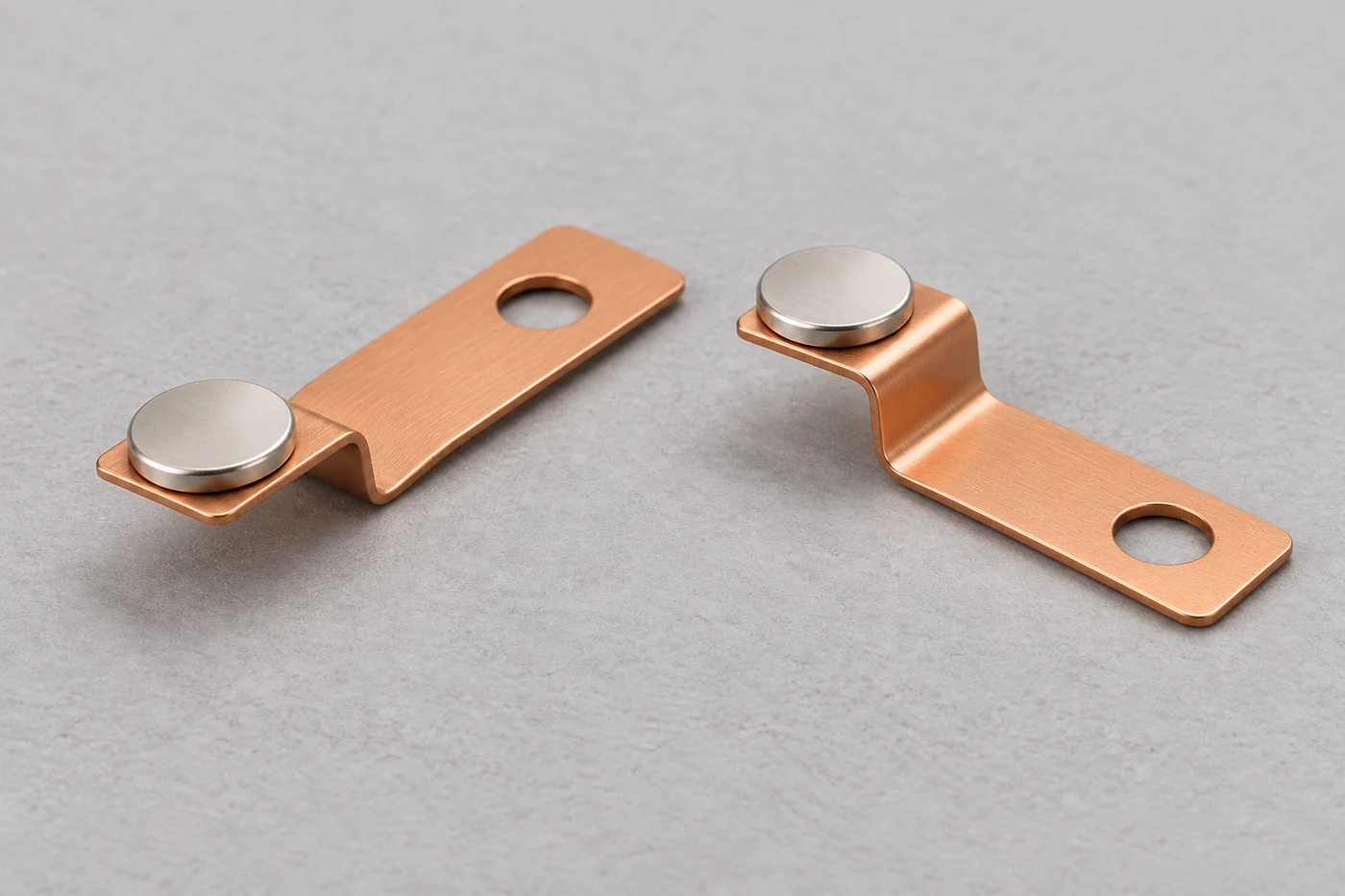
도어 인터록용 접점은 작은 머리부와 체결부가 결합된 리벳형, 별도 접점 팁을 붙인 형상 등으로 구성할 수 있습니다. 낮은 원형 머리부를 사용하는 구조에서는 머리 지름과 높이, 접촉면 곡률, 가장자리 형상을 접촉력·정렬 여유·마모 거동에 맞춰 도면으로 지정합니다. 각 치수는 접촉 기능과 체결 공간에서 서로 다른 역할을 가집니다.
눈으로 보이는 머리부 전체가 동시에 전류를 전달하는 면적은 아닙니다. 실제 금속 접촉은 표면의 미세한 돌기와 국부 변형이 만드는 영역에서 이루어집니다. 같은 지름의 접점도 표면 상태, 접촉력, 정렬 상태가 다르면 실제 접촉 영역과 저항이 달라질 수 있습니다.
접점 지름과 접촉력의 연결
접점 지름을 키우면 열을 받아들이는 체적이나 정렬 여유를 확보하는 데 도움이 될 수 있지만, 접촉력까지 충분해지는 것은 아닙니다. 넓은 외형 면적과 안정적인 금속 접촉을 구분해서 검토해야 합니다. 반대로 작은 접점에 힘을 과도하게 집중시키면 눌림, 마모, 가동편의 변형이 문제가 될 수 있습니다.
가동접점과 고정접점은 닫힌 상태에서 요구한 위치로 맞아야 합니다. 중심이 어긋나거나 한쪽 가장자리만 먼저 닿으면 국부 발열과 비대칭 마모가 발생하기 쉽습니다. 접점의 높이 편차, 가동편 비틀림, 단자 성형 각도를 하나의 접촉 정렬 문제로 연결해서 관리합니다.
개폐 중 접촉면이 미끄러지는 와이핑 동작이 있는 구조에서는 이동량과 방향을 따로 정의합니다. 와이핑은 일부 피막에 영향을 줄 수 있지만 과도하면 마모와 파편을 늘릴 수 있습니다. 모든 스냅 접점에 동일한 와이핑 동작이 있다고 가정하거나, 미끄럼만으로 오염 문제가 해결된다고 설명하지 않습니다.
07은접점과 프레스 부품의 접합 품질
은접점이 가동편에 붙어 있다는 외관만으로 접합 품질을 판단하기는 어렵습니다. 접합부는 반복 움직임을 견디는 기계적 고정부인 동시에 전류를 전달하는 경로가 될 수 있습니다. 따라서 체결 유지력과 전기저항, 접점 높이와 가동편 변형을 함께 확인해야 합니다.
| 방식 | 주요 관리 항목 | 완성품에서 확인할 결과 |
|---|---|---|
| 리벳 체결 | 축부와 구멍의 관계, 돌출량, 성형 하중·변위, 머리부 지지 | 흔들림·회전, 균열, 접점 높이, 가동편 휨 |
| 저항 용접 | 전극 접촉 상태, 전류·시간·가압, 표면 청정도 | 접합 강도, 접합부 저항, 비산·열 변형 |
| 브레이징 등 열 접합 | 재료 적합성, 가열 범위, 접합층과 잔류물 | 접합 연속성, 스프링 특성 변화, 청정 상태 |
리벳팅에서의 머리부와 가동편 보호
리벳 체결은 접점 축부를 구멍에 넣고 반대편을 성형해 고정하는 방식입니다. 성형이 부족하면 체결부가 움직일 수 있고, 지나치면 가동편이 휘거나 접점 머리부가 손상될 수 있습니다. 앞쪽 접촉면을 적절하게 지지하면서 뒤쪽 체결부에 필요한 변형을 집중시키는 공구와 지그 설계가 중요합니다.
성형된 뒤쪽을 무조건 전기 접촉면으로 사용하는 것은 아닙니다. 양면 접촉 기능이 필요한 설계라면 뒤쪽의 재료 구성, 형상, 표면과 접촉 하중을 별도로 지정해야 합니다. 단순 체결용 리벳팅과 앞뒤 양면접점의 요구 사항은 구분합니다.
열 접합과 스프링 특성의 동시 검토
저항 용접은 작은 영역에 열을 집중시켜 접합하지만 인접한 가동편의 조질이나 도금층에 미치는 영향을 확인해야 합니다. 전류와 시간만으로 조건을 관리하기보다 가압 상태, 전극 마모, 접합 전 표면을 함께 관리합니다. 브레이징을 적용하는 구조에서도 가열로 인한 탄성 특성 변화와 잔류물을 평가해야 하며, 모든 도어 스위치가 같은 접합 방법을 사용하는 것은 아닙니다.
접합 조건을 확정할 때는 단품 파괴 시험과 전기적 확인을 연결합니다. 높은 분리 하중이 나와도 전류 경로에 불안정한 경계면이 남을 수 있고, 초기 저항이 낮아도 반복 동작 후 느슨해질 수 있습니다. 요구 수명 이후의 접합 상태까지 포함해야 접점과 프레스 가동편의 조합을 평가할 수 있습니다.

08도어 래치와 접점 조립의 공차 배분
도어 인터록 스위치 접점의 상태는 금속 부품 치수만으로 결정되지 않습니다. 도어 힌지의 위치와 처짐, 래치 돌출량, 스위치 브래킷 위치, 플런저 높이, 케이스 변형이 순서대로 영향을 줍니다. 이 공차들이 한 방향으로 겹치면 문을 닫아도 작동이 부족하거나, 정상 위치에서 액추에이터가 과도하게 눌릴 수 있습니다.
닫힘 조건과 열림 조건의 별도 검토
닫힘 측에서는 최악 조건에서도 액추에이터가 가장 늦은 작동 위치를 충분히 지나야 합니다. 동시에 최대 누름 조건이 허용 종단을 넘지 않아야 합니다. 열림 측에서는 액추에이터가 가장 불리한 복귀 위치를 지나 안정적으로 해제되어야 합니다. 두 조건을 평균 치수 한 점으로만 검토하면 작동 여유와 복귀 여유 중 하나가 누락되기 쉽습니다.
변위를 비교할 때는 같은 기준점과 같은 좌표 방향을 사용합니다. 제조사 도면에서 높이로 표기된 OP·RP와 조립 설계에서 누름량으로 계산한 값을 바로 비교하면 부호와 기준이 어긋날 수 있습니다. 측정 기준을 통일한 후 문 닫힘·열림의 범위와 스위치 작동 범위를 겹쳐 보는 방식이 명확합니다.
접점 내부 공차와 외부 기구 공차
접점 머리 높이, 가동편 성형 높이, 고정 단자 높이는 내부 접촉 위치와 힘에 영향을 줍니다. 외부에서는 브래킷의 장착 위치와 래치의 경사가 액추에이터 변위에 영향을 줍니다. 내부 기능 치수와 외부 장착 치수를 분리해서 관리하되, 최종 검증에서는 하나의 조립 상태로 연결해야 합니다.
접점이 둘 이상인 기구에서는 전환 순서와 시간 관계도 설계 대상입니다. 개별 스위치가 각각 치수 규격에 들어와도 조립 위치 차이 때문에 시스템이 요구하는 순서가 달라질 수 있습니다. 필요한 순서는 해당 가전의 회로와 기구 요구로 정하고, 대표 도어 동작 속도와 조립 공차의 조합에서 확인합니다.
양산 검사는 최악 조건을 재현한 시편이나 조정 가능한 기능 지그를 활용할 수 있습니다. 다만 지그가 도어의 실제 힘 전달 방향을 재현하는지 확인해야 합니다. 플런저를 수직으로 누르는 검사만으로 경사진 래치에서 생기는 측하중이나 마찰까지 검증했다고 보기 어렵습니다.
화살표 키로 시점 조절
고정 접점과 단자, COM 가동편, 누름자와 절연 지지부가 함께 위치를 결정합니다. 접점 자체의 외형이 같아도 단자의 절곡 형상과 지지 높이가 달라지면 조립 후 기능이 달라질 수 있습니다.
개별 부품의 치수가 조립 후 접촉 위치와 작동 여유로 이어지는 관계
09돌입전류·접점 발열·바운스의 상호작용
스위치에 표시된 전류 값은 정해진 전압과 부하 조건에 연결됩니다. 같은 정상 전류라도 저항성 부하, 모터·솔레노이드와 같은 유도성 부하, 입력 커패시터가 있는 전자회로는 투입과 차단 순간의 전류가 다릅니다. 도어 인터록 스위치 접점은 정상 운전 전류와 순간 부하를 구분해서 검토해야 합니다.
투입과 차단에서 달라지는 접점 부담
투입 순간에는 돌입전류와 접점 바운스가 겹칠 수 있습니다. 바운스는 처음 닿은 접점이 미세하게 튀어 재접촉하는 현상으로, 짧은 시간에도 반복적인 국부 발열이나 아크를 유발할 수 있습니다. 단순히 “딸깍” 소리가 난다는 사실만으로 바운스가 작거나 용착 가능성이 낮다고 판단하지 않습니다.
차단 순간에는 부하의 저장 에너지와 회로 조건이 아크에 영향을 줍니다. AC와 DC는 전류가 감소하고 아크가 소멸하는 조건이 같지 않으므로 동일한 전류 수치만으로 개폐 능력을 바꾸어 적용할 수 없습니다. 접점 재질, 개방 속도, 간격과 기구의 복귀 힘을 실제 부하 시험과 연결해야 합니다.
전류 경로별 발열의 구분
저항에 의한 전력 손실은 기본적으로 I²R에 비례합니다. 그러나 측정한 스위치 단자 간 저항에는 접촉 계면뿐 아니라 가동편, 단자, 접합부의 저항이 함께 들어갑니다. 온도 상승이 크다고 접점 재질만 바꾸기보다, 어느 구간에서 손실이 집중되는지 구분해야 합니다.
접합부의 불안정, 가동편의 좁은 단면, 접촉력 감소는 서로 다른 원인입니다. 온도가 올라가 가동편의 힘이 감소하고, 그 결과 접촉 상태가 더 나빠지는 연쇄 작용도 검토합니다. 열이 빠져나가는 단자와 배선, 케이스의 구조도 영향을 주므로 금속 접점 단품의 시험과 완성 스위치의 시험을 구분해야 합니다.
평가 항목은 전압·전류의 시간 파형, 바운스 양상, 투입 및 차단 시점, 안정 통전 후 온도로 나눕니다. 하나의 최대값만 남기는 것보다 시험 조건과 변화 양상을 기록하면 재질 변경, 리벳 조건 변경 또는 가동편 조질 변경의 영향을 비교하기 쉽습니다.
10습기·세제·조리 환경에 대한 접점 관리
가전 도어 주변은 기기 내부의 건조한 시험 공간과 환경이 다를 수 있습니다. 세탁기 주변의 습기와 세제 성분, 조리 기기 주변의 수증기와 오염물, 설치 장소의 먼지가 접점이나 기구에 영향을 줄 수 있습니다. 어떤 물질이 어느 경로로 유입되는지 구분해야 접점 재질과 케이스 구조를 합리적으로 선정할 수 있습니다.
표면 피막과 이물의 영향
은계 표면에는 환경에 따라 변색이나 피막이 생길 수 있으며, 미소 신호에서는 얇은 표면층도 접촉 안정성에 영향을 줄 수 있습니다. 금속 칩, 섬유, 건조 잔류물은 접점 사이에 끼거나 가동편의 움직임을 방해할 수 있습니다. 외관이 깨끗하다는 사실과 전기적 접촉면이 관리되었다는 사실은 구분해서 확인합니다.
제조 과정에서는 프레스 윤활유, 세척제, 접합 잔류물과 포장재에서 이동하는 오염을 함께 살핍니다. 세척을 강하게 하는 것만으로 해결되지 않으며, 세척 후 잔류물과 건조 상태, 접점 재오염 여부까지 확인해야 합니다. 윤활이 필요한 기구에서도 윤활제가 접촉면으로 이동하지 않도록 적용 위치와 양을 관리합니다.
밀폐 구조와 실제 사용 조건
밀폐형 또는 방수형이라는 명칭도 모든 환경에 대한 내성을 뜻하지는 않습니다. 액추에이터 주변과 단자 인출부의 구조, 실제 장착 방향, 결로 가능성과 적용 물질의 적합성을 함께 확인합니다. 물의 침입을 줄이는 구조와 특정 가스나 화학 물질에 대한 내성은 서로 다른 검토 항목입니다.
환경 시험 뒤에는 단순 외관 검사에 더해 작동·복귀 위치, 단자 간 저항, 개폐 상태와 기구 마찰의 변화를 확인합니다. 부식된 흔적이 적더라도 접촉력이나 복귀가 달라질 수 있고, 초기에는 정상인 접점도 반복 개폐에서 오염이 이동하면서 특성이 바뀔 수 있기 때문입니다.
포장과 보관 역시 제조 품질의 연장입니다. 세척된 접점의 기능면이 서로 마찰하거나 손에 직접 닿지 않도록 취급 방법을 정하고, 재질·로트·후공정이 혼입되지 않게 관리하면 조립 이후 원인을 추적하기 수월해집니다.
11접점저항·작동력·체결 상태의 검사
도어 인터록용 접점 부품은 치수와 외관에 합격해도 조립 후 전기적 기능이 달라질 수 있습니다. 검사 항목을 소재·형상, 접합, 기구 동작, 전기적 상태로 나누고 각각의 결과를 연결해야 합니다. 특히 측정 시 접점에 가하는 힘과 액추에이터 위치를 고정해야 로트 간 비교가 의미를 가집니다.
| 검사 영역 | 대표 확인 항목 | 측정에서 놓치기 쉬운 부분 |
|---|---|---|
| 형상·정렬 | 접점 높이, 중심 위치, 가동편 비틀림, 기능면 상태 | 지그가 부품을 강제로 펴는 영향 |
| 접합 상태 | 체결 유지, 접합 강도, 균열, 단면 상태 | 초기 외관과 내부 결합 상태의 차이 |
| 기구 특성 | 작동력, 복귀력, OP·RP, 힘–변위 곡선 | 누르는 방향·속도·측하중의 차이 |
| 전기 특성 | 단자 간 저항, 전압 강하, 접점 바운스 | 시험 전압·전류와 측정 위치 |
| 절연 특성 | 개방 상태의 절연과 규정 시험 | 닫힌 접점의 저항 측정과 다른 목적 |
4선식 측정의 적용 범위
작은 저항을 평가할 때 4선식 측정은 전류를 흘리는 선과 전압을 읽는 선을 분리해 리드선 등의 영향을 줄이는 데 유용합니다. 다만 스위치 단자에서 측정하면 단자부터 접점까지의 전류 경로가 포함됩니다. 4선식이라는 이유만으로 순수한 접촉 계면저항만 분리해서 측정한 것은 아닙니다.
측정 전압이나 전류가 표면 피막의 상태를 바꾸면 미소 부하에서의 실제 특성과 다른 결과가 나올 수 있습니다. 제품의 기능과 적용 부하에 맞춰 시험 조건을 정하고, 낮은 신호 조건에서의 측정과 부하 통전 후의 측정을 구분해 기록합니다.
검사 결과를 연결하는 판정 방식
저항이 높은 부품을 발견했을 때 접점 재질의 문제로 바로 분류하지 않습니다. 작동 위치가 충분한지, 접촉 정렬이 맞는지, 접합부가 안정적인지, 표면에 잔류물이 있는지를 순서대로 연결해 확인합니다. 반대로 저항이 낮더라도 접점이 제대로 떨어지지 않거나 복귀 위치가 벗어나면 기능 합격으로 볼 수 없습니다.
출하 검사와 개발 시험도 목적이 다릅니다. 출하 검사는 검증된 공정의 변동을 검출하고, 개발 시험은 재료·설계·공정의 한계를 확인합니다. 모든 시험을 모든 부품에 반복하기보다, 기능에 직접 연결되는 관리 항목과 주기 검증 항목을 나누어 검사 계획을 구성합니다.
12기계 수명과 전기 수명의 검증
무부하로 반복 작동하는 기계 수명 시험과 전류를 개폐하는 전기 수명 시험은 같은 의미가 아닙니다. 기계 시험에서는 스프링, 지지부, 액추에이터의 마모와 변형을 살피고, 전기 시험에서는 여기에 아크, 용착, 재료 소모와 접촉 상태 변화가 더해집니다. 반복 횟수만 같아도 부하와 작동 조건이 다르면 결과를 직접 비교하기 어렵습니다.
실제 사용 조건을 반영한 시험 조합
전기 수명 조건에는 전압, 정상 전류, 돌입 조건, 부하 종류, 개폐 주기, 온도와 액추에이터 이동을 포함합니다. 도어를 빠르게 닫는 조건과 천천히 닫는 조건, 공차가 불리한 장착 위치가 기구에 미치는 영향을 확인하고, 필요한 경우 환경 노출과 반복 개폐를 조합합니다.
시험 도중에는 최종 고장 여부만 보는 대신 접점저항, 온도 상승, OP·RP와 복귀 상태의 추세를 기록합니다. 접점이 계속 통전되더라도 저항이나 작동 위치가 일정 방향으로 이동하면 재료 소모, 접합부 변화, 스프링 특성 저하를 조사할 근거가 됩니다.
부품 성능과 완성 가전의 평가
스위치 부품의 전기적 정격이나 인증이 완성 가전의 적합성을 그대로 대신하지는 않습니다. 가전에서는 도어 기구, 제어 회로, 절연 구조, 장착 조건과 요구되는 동작 관계가 함께 평가됩니다. 전자레인지와 세탁기처럼 동작 목적과 환경이 다른 기기는 해당 제품에 적용되는 요구 사항에 따라 검증 범위를 정해야 합니다.
개방된 접점 간격과 단자 주변의 절연 거리도 구분합니다. 접점을 떨어뜨리는 동작이 확보되었다고 해서 케이스 내부의 절연 경로나 단자 간 절연이 자동으로 확보되는 것은 아닙니다. 이 항목들은 접점 제조 치수와 연결하되 완성 스위치와 기기의 절연 설계 안에서 검토합니다.
재질, 접점 두께, 가동편 조질, 리벳 조건이나 용접 조건을 바꿀 때는 변경이 영향을 주는 시험을 다시 선정합니다. 외형 치수가 같다는 이유만으로 기존 수명 결과를 모두 그대로 적용하지 않고, 전류 경로·탄성·표면·접합의 변화 범위를 기준으로 재검증합니다.
13접점·프레스 부품 제작 사양과 양산 관리
가전 도어 인터록 스위치 접점의 제작 사양은 작은 금속 부품의 치수를 나열하는 수준에서 끝나지 않습니다. 어느 면이 전기적으로 맞닿는지, 어느 부분이 탄성 변형을 담당하는지, 어느 치수가 작동 위치와 접촉력에 영향을 주는지를 도면에서 구분해야 합니다. 이 기능 구분이 명확해야 프레스, 접점 성형, 접합과 검사 조건이 같은 방향으로 맞춰집니다.
| 개발 정보 | 구체화할 내용 | 제작·검증의 연결 |
|---|---|---|
| 전기적 역할 | 직접 부하 개폐 또는 상태 신호, 적용 부하 조건 | 접점 재질과 전기 시험 조건 |
| 접점 사양 | 재료 등급, 접촉면, 머리·축부 형상, 접합 방식 | 성형 공정과 기능면 검사 |
| 프레스 사양 | 재료·조질·두께, 굽힘·지지 위치, 버 방향 | 탄성 특성과 반복 변위 평가 |
| 조립 조건 | 장착 기준, 작동·복귀 범위, 허용 이동량 | 공차 검토와 기능 지그 |
| 품질 기록 | 소재 로트, 접합 조건, 검사 결과, 변경 이력 | 문제 발생 시 원인 추적과 재현 |
시제품에서 양산으로 이어지는 기준
시제품에서는 기능이 성립하는 조건을 찾고, 양산에서는 그 조건을 반복해서 유지할 수 있는 범위를 확인합니다. 한 개의 시편에서 낮은 저항과 정확한 작동점이 나왔다는 결과만으로 공정이 안정되었다고 판단하지 않습니다. 소재와 조질의 편차, 금형 마모, 리벳 성형량 또는 용접 전극 상태가 바뀔 때 핵심 기능이 얼마나 움직이는지 확인해야 합니다.
관리 도면에는 모든 치수를 같은 중요도로 취급하기보다 접점 높이, 접합부, 탄성부, 장착 기준처럼 기능과 연결되는 항목을 구분합니다. 치수와 힘, 저항의 상관관계를 확보하면 외관으로 드러나지 않는 변화도 공정 단계에서 포착하기 쉬워집니다.
변경 이력과 재현 가능한 검사
소재 성적서의 로트, 프레스 생산 이력, 접점 재질과 접합 조건, 주요 검사 결과를 연결해 기록합니다. 동일한 이름의 접점이라도 재료 등급이나 제조 경로가 달라질 수 있으므로 변경 내용을 완성품 기준으로 검토해야 합니다. 검사 지그나 측정 조건을 바꾼 경우에도 이전 데이터와 비교 가능한지 확인합니다.
가전 도어 인터록용 부품의 개발 협의에서는 접점 도면과 가동편 도면에 더해 실제 작동 방향, 요구 이동 범위, 부하 조건과 검증 기준을 함께 준비하면 효과적입니다. 은접점의 전기적 특성과 프레스 부품의 탄성·치수를 하나의 조립 기능으로 연결하는 것이 안정적인 설계와 제조의 중심입니다.
Appliance Door-Interlock Contacts: Silver Contacts and Stamped Moving Members
Appliance door-interlock contacts connect door movement with an electrical switching state. Silver-based contacts carry current while stamped moving members repeatedly establish the required force and position. Stable operation depends on their interaction. The following engineering framework connects contact materials and snap mechanisms with riveting or welding, assembly tolerances, heating and endurance.
01Functions and applications of appliance door-interlock contacts
Appliance door-interlock contacts convert the mechanical movement of a door or latch into an electrical switching state. Small silver-based contact pieces make and break against a moving stamped member, communicating an operating condition or switching load current in the circuit for which the assembly was designed. Reliable door-state transfer requires more than a suitable contact material: spring behavior, contact height, actuator position and assembly tolerances must work together.
A microwave latch-operated switch and a washing-machine door lock both respond to a door, but they do not have identical structures or responsibilities. A microwave may use compact switches actuated by latch movement. A washing-machine assembly can combine physical door retention with electrical state detection. The current path and the path through which force reaches the contact therefore need to be identified for each application.
| Function | Purpose | Contact and stamped-part considerations |
|---|---|---|
| Door-position detection | Translate the position of a door or latch into an electrical state | Operating and release positions, contact resistance and signal stability |
| Operating-circuit switching | Connect or disconnect a specified power or load circuit | Load type, inrush current, arcing and temperature rise |
| Mechanical door locking | Restrict opening under defined operating conditions | Relationship between the lock and sensing contact, actuation sequence and retention-force path |
Separation of detection and mechanical retention
An electrical transition does not by itself prove that a door has been mechanically locked. The positions of the locking pin or slider, the latch engagement and the position actually detected must be related explicitly. Conversely, a door can appear closed while the movement delivered to a switch is insufficient to pass its operating position.
Development should first establish whether the contact switches a load directly or supplies a state signal to a control circuit. Linking mechanical drawings with electrical load conditions then makes it possible to review the silver contact, stationary terminal and stamped moving member as an interacting assembly, rather than as three unrelated shapes.
02Snap action and the stationary and moving contact structure
A mechanical snap switch stores spring energy while its actuator moves. When the mechanism passes its transition point, that energy drives the moving contact rapidly to its other state. This helps achieve a decisive contact transition even when the door moves slowly. It does not, however, establish consistent performance outside the specified actuation speed and travel range.
Current passes from the terminal to the contact face through a conductive moving member or another designed conductor. Some mechanisms combine spring and conductor functions in one piece; others separate the elastic element from the current path. Material and geometry are allocated to conduction, elasticity and support, with the assembled current path providing the basis for their evaluation.
Reference state for COM, NO and NC
COM identifies the common terminal. NO and NC describe the contact relationship in the reference state with no external force applied to the actuator. In a typical changeover arrangement, COM–NC is closed and COM–NO is open in that state. Pressing the actuator changes the relationship at the specified operating position.
These markings cannot be translated directly into “door open” and “door closed.” Their relationship to door position depends on whether closing the door presses or releases the switch through its latch mechanism. A drawing should distinguish the actuator reference state from the appliance door state and define the required electrical result for each.
Snap action and direct opening
Snap action is a mechanism characteristic that produces rapid switching with stored elastic energy. Direct opening, in which actuator movement provides a specified mechanical means of separating contacts, is a separate characteristic requiring explicit confirmation. It is not an automatic property of every miniature snap switch and must be established from the selected model and its conditions of application.
A structural review of door-interlock contacts should include the return movement as well as the closed-contact arrangement. Clearance from the housing and terminals, remaining return force and alignment of the contact centers after assembly all affect the consistency of repeated operation.
Arrow keys change the view
The conductive path runs from the COM terminal through the moving spring to the contact. NC and NO are defined relative to the contact state with the actuator in its free position.
A representative SPDT transfer arrangement with upper and lower fixed contacts and a COM moving blade
03Operating position, release position and overtravel
Door movement reaches the contact mechanism through a latch, lever or plunger. The distance moved by the door, the travel of the actuator and the gap between the contacts are different quantities. Lever ratios and the motion of the snap mechanism prevent a one-to-one relationship between plunger displacement and contact separation.
| Term | Meaning | Design consideration |
|---|---|---|
| FP · Free position | Actuator position with no external force | Assembly datum and unloaded return condition |
| OP · Operating position | Position at which the contacts change state during actuation | Minimum available movement on door closure |
| RP · Release position | Position at which the contacts return as actuation is removed | Return margin during door opening |
| PT · Pretravel | Movement from free position to operating position | Movement transmitted by the latch or lever |
| OT · Overtravel | Permitted additional movement beyond the operating position | Avoidance of excessive travel and mechanical damage |
| MD · Movement differential | Travel difference between operating and release positions | Separation of the two transitions and state stability under vibration |
Travel margin after switching
If the closed door leaves the actuator close to OP, dimensional variation, housing distortion or vibration can destabilize the switching state. Excessive depression beyond the permitted endpoint can permanently deform the moving member or damage the housing. The closed-door position needs both a sufficient margin past operation and a margin before the travel limit.
One fixed percentage of overtravel cannot be applied to every door switch. Recommended stroke ranges differ with the selected mechanism and actuator. Tolerances should be allocated using the specification for the actual model. The structure that stops and supports a closing door should also be distinguished from the switch actuator, so that the plunger is not required to absorb the door-stop load.
The external force needed to operate the actuator is not identical to the force between the electrical contact faces. Levers and springs transform the applied force. Measuring operating force alone therefore cannot establish adequate contact pressure. A combined review of the force–displacement curve, transition positions and electrical stability after the transition gives a more useful assessment.
Arrow keys change the view
Actuator movement does not change the initial contact state until the operating position is reached. Travel from the free position to the operating position is pretravel, which is considered together with the position of the door actuator.
Actuator and contact positions distinguishing pretravel, overtravel and movement differential
04Silver contact materials matched to the electrical load
Silver-based appliance contacts must conduct current while tolerating arcing, material transfer, welding and wear during repeated switching. AgNi and AgSnO₂ are representative material families worth evaluating, but neither is universally superior for every load. Selection requires the switching-current waveform, voltage, load characteristics, contact force and opening dynamics, not merely the nominal current.
| Material family | Characteristics to evaluate | Related selection conditions |
|---|---|---|
| AgNi · Silver–nickel | Balance of conduction and switching durability using a silver matrix and nickel phase | Composition and manufacturing condition, contact force, arc erosion and material transfer |
| AgSnO₂ · Silver–tin oxide | Welding resistance and switching behavior associated with a dispersed oxide phase | Inrush duty, contact resistance, formulation and forming or joining requirements |
| Gold-based surface or gold-alloy contact | Reduction of surface-film effects in low-level circuits | Minimum applicable load, surface construction, contact force, environment and operating history |
Power switching and low-level signals
A contact switching a power load such as a heater has different requirements from one carrying a small detection current into an electronic circuit. At low levels, surface films may remain electrically significant, making contamination or tarnish relevant to signal resistance. In power switching, arcing, concentrated heating, welding and contact-material loss become more prominent concerns.
Nickel in AgNi is a metallic phase; tin oxide in AgSnO₂ is an oxide phase. The two should not be described as the same kind of oxide-dispersion material. A family name also does not identify a particular composition or manufacturing route. Selection needs to connect a defined supplier grade with the performance of the finished contact.
A gold-based surface is not a universal solution for all loads. After power switching has consumed or altered a surface layer, the original low-level behavior cannot simply be assumed to remain available. Likewise, high material conductivity does not directly establish a high current rating for the completed switch. Terminal and blade heating, insulation construction and switching tests must also be satisfied.
05Elastic behavior and repeated durability of the stamped moving member
The stamped moving member supports the contact and accommodates repeated displacement. Depending on the construction, it also carries current, requiring both electrical and mechanical evaluation. For copper-alloy candidates, the material designation must be connected to temper, thickness, rolling direction, bend geometry and thermal history in the drawing and process requirements.
Thickness and effective spring length
Changing strip thickness can substantially change bending stiffness and the operating force, even when the alloy remains the same. A shorter effective spring length or a shifted support position also changes its behavior. If a riveted or welded attachment extends into the intended elastic region, the resulting force–displacement relationship can differ from the design.
A higher-strength alloy does not imply a proportional increase in elastic modulus. Elastic modulus contributes to stiffness, while yield behavior and spring limits determine the usable range before permanent deformation. A material substitution therefore requires evaluation of maximum deflection and residual set, as well as initial operating force.
Functional surfaces in stamping
Shearing burrs and tool wear are more than appearance issues. A burr near an edge under high tensile stress, or close to a contacting feature, can become a crack initiation site or an unwanted friction point. Bend radius, corner transitions, direction-dependent bendability and surface damage should be reviewed together, with burr direction and edge-finishing requirements tied to function.
When a blade remains deflected at elevated temperature, stress relaxation can reduce the force it supplies. This is distinct from fatigue under repeated movement. A part that meets the initial force specification can show changed force after thermal dwell or a changed return position after cycling. Material and temper should therefore be selected against the completed assembly’s temperature and displacement conditions.
Dimensional inspection should include contact-center height, the boundary between support and spring regions, formed angles and twist, not only overall length and hole position. Free-state inspection and inspection under assembly constraints need separate definitions. An overly restrictive measuring fixture can otherwise force a distorted blade into an apparently correct position.
Responsibilities of fixed terminals and moving blades
A stamped stationary terminal supports the fixed contact and maintains its position and current path. A moving blade must instead accommodate the specified displacement repeatedly while providing contact force and return behavior. Although both can be made from strip, mounting stiffness in a fixed terminal and elasticity in a moving blade serve different purposes. Supports, bends and material condition should be assigned to those respective functions.
06Contact geometry and the real conducting area
Door-interlock contacts may use a rivet construction with a head and attachment shank, or a separately attached contact tip. Where a low circular head is used, its diameter, height, working-face curvature and edge profile are specified against contact force, alignment allowance and wear behavior. These dimensions have distinct roles in electrical contact and in the space available for attachment.
The entire visible head is not necessarily the area that conducts current at one instant. Metal-to-metal contact occurs at local regions formed by microscopic surface features and deformation. Contacts with identical diameters can therefore have different real contact areas and resistance when their surface condition, contact force or alignment differs.
Contact diameter and applied force
Increasing contact diameter may provide additional thermal mass or alignment allowance, but it does not automatically produce adequate contact force. Geometric area and stable metallic contact need separate evaluation. Conversely, excessive concentration of force on a small contact can cause indentation, wear or deformation of the supporting blade.
The stationary and moving contacts must meet at their intended positions when closed. Lateral offset or first contact at a single edge can promote localized heating and uneven wear. Variation in contact height, blade twist and the formed angle of a terminal should be managed as parts of one alignment problem.
If the mechanism includes wiping motion between contact faces, its direction and travel require their own definition. Wiping may affect some films, but excessive movement can increase wear and debris. Identical wiping action should not be assumed for all snap mechanisms, nor should sliding movement alone be treated as a complete solution to contamination.
07Attachment quality between the contact and stamped part
The appearance of a contact attached to a blade does not establish joint quality. The joint can be both a mechanical attachment under repeated movement and a current-carrying path. Retention strength and electrical resistance must therefore be evaluated together with contact height and distortion of the stamped member.
| Method | Main process controls | Finished-assembly results |
|---|---|---|
| Riveting | Shank-to-hole relationship, protrusion, forming force and displacement, head support | Looseness or rotation, cracks, contact height and blade distortion |
| Resistance welding | Electrode condition, current, time, pressure and surface cleanliness | Joint strength and resistance, expulsion and thermal distortion |
| Brazing or another thermal joint | Material compatibility, heated area, joint layer and residues | Joint continuity, changes to spring behavior and cleanliness |
Protection of the head and blade during riveting
Riveting places the contact shank through a hole and forms the opposite end to retain it. Insufficient forming can leave movement in the joint; excessive forming can bend the blade or damage the contact head. The tooling must support the working face appropriately while concentrating the required deformation in the attachment end.
The formed back of a rivet is not automatically an electrical contact face. If a design requires double-sided contact function, its rear material construction, geometry, surface and contact load need explicit requirements. Simple mechanical riveting and a front-and-rear contact arrangement should be treated as different specifications.
Thermal joining and spring behavior
Resistance welding concentrates heat locally, but its effect on the temper and coating of the adjacent blade still requires evaluation. Control should include pressure, electrode wear and surface condition before joining, rather than current and time alone. Where brazing is used, changes in elastic behavior and residual material must also be assessed. Door switches do not all use one attachment method.
Joint qualification should connect destructive mechanical assessment with electrical measurements. A high separation force does not rule out an unstable current-carrying interface, and low initial resistance does not prove that the assembly will remain tight after repeated operation. Evaluation should include the joint condition after the required duty, so that the contact and stamped blade are qualified as a combination.
08Tolerance allocation between the door latch and contact assembly
The switching state is not determined by metal-part dimensions alone. Hinge position and sag, latch projection, switch-bracket position, plunger height and housing distortion form a chain of influences. When their variations accumulate in one direction, the actuator may receive insufficient movement with the door closed, or excessive depression at the nominal door position.
Separate checks for closure and release
On closure, even the least favorable assembly must move sufficiently beyond the latest operating position. At the same time, maximum depression must remain within the permitted endpoint. During opening, the actuator must pass the least favorable release position and return reliably. Reviewing only an average dimensional condition can omit either the operating margin or the return margin.
Comparisons need a common datum and coordinate direction. An OP or RP given as a height on a manufacturer drawing cannot be compared directly with an assembly calculation expressed as depression without converting the reference. Once the coordinates are consistent, the available closed- and open-door travel ranges can be compared clearly with the switch’s functional range.
Internal contact tolerances and external installation tolerances
Contact-head height, formed blade height and stationary-terminal height affect the internal contact location and force. Bracket position and latch angle affect the displacement delivered externally. These two groups of dimensions should be controlled separately but evaluated together in the completed assembly.
A mechanism containing multiple switches can also have requirements for transition order and timing. Individually conforming switches do not guarantee that the installed system follows the intended sequence if mounting positions differ. The sequence belongs to the requirements of the particular appliance circuit and mechanism, and should be verified across the relevant door speeds and assembly tolerances.
Worst-case samples or an adjustable functional fixture can support production qualification. The fixture must reproduce the actual force direction. A test that presses the plunger vertically does not necessarily evaluate the side load or friction introduced by an inclined latch.
Arrow keys change the view
The fixed contacts and terminals, COM moving blade, actuator and insulating support establish the final positions together. Identical contact outlines can behave differently when terminal bends or support heights change.
How individual component dimensions determine assembled contact location and operating margin
09Interaction of inrush current, contact heating and bounce
A switch current rating is associated with specified voltage and load conditions. Resistive loads, inductive loads such as motors or solenoids, and electronic circuits with input capacitance can have different make-and-break behavior even at the same normal current. Door-interlock contacts therefore need separate consideration of steady operating current and transient duty.
Different stresses during making and breaking
Inrush current can coincide with contact bounce during closure. Bounce is the brief separation and recontact following the first touch. Even over a short interval, it can cause repeated localized heating or arcing. An audible click does not establish low bounce or a low likelihood of contact welding.
During opening, stored load energy and circuit conditions influence the arc. AC and DC do not provide identical conditions for current decay and arc extinction, so equal current values cannot be used to transfer switching capability between them. Contact material, separation dynamics, gap and restoring force must be evaluated with the actual load duty.
Heating along the current path
Resistive power loss is fundamentally proportional to I²R. However, the resistance measured between switch terminals includes the blade, terminals and joints as well as the contact interface. If temperature rise is excessive, the location of concentrated loss should be identified before changing contact material alone.
An unstable joint, a restricted blade cross-section and inadequate contact force are different causes. A feedback process may also develop: heating reduces spring force, which worsens contact conditions and increases heating. Heat transfer through the terminals, conductors and housing affects the outcome. Tests on an isolated contact piece therefore need to be distinguished from tests on a completed switch.
Evaluation can separate voltage and current waveforms, bounce behavior, make-and-break timing and temperature during stabilized conduction. Recording test conditions and trends, rather than only a maximum value, makes material changes, rivet-process changes and blade-temper changes easier to compare.
10Moisture, detergent and cooking-environment exposure
Conditions around an appliance door can differ from a dry laboratory environment. Humidity and detergent constituents around a washer, vapor and contamination around a cooking appliance, and dust at the installation site can affect both contacts and mechanisms. Identifying the substance and its entry path supports a more rational selection of contact material and enclosure construction.
Surface films and foreign particles
Silver-based surfaces can develop tarnish or films depending on the environment. In low-level circuits, even a thin layer can influence contact stability. Metal chips, fibers and dried residues may enter between contact faces or interfere with blade movement. A clean appearance and a controlled electrical working surface are therefore different inspection objectives.
Manufacturing review should include stamping lubricant, cleaning agents, joining residues and contamination transferred from packaging. More aggressive cleaning is not a complete answer: residue after cleaning, drying and subsequent recontamination also need control. Where the mechanism requires lubrication, the application location and quantity should prevent migration toward the contact interface.
Sealed construction and actual exposure
A sealed or waterproof designation does not establish resistance to every environment. Actuator and terminal-exit construction, installation orientation, condensation and compatibility with the actual substances must be considered. Limiting water ingress and resisting a particular gas or chemical are separate performance questions.
After environmental exposure, inspection should cover operating and release positions, terminal resistance, switching state and mechanical friction as well as appearance. Limited visible corrosion does not guarantee unchanged force or return behavior. Initially normal contacts can also change during cycling as contamination moves within the mechanism.
Packaging and storage extend the manufacturing controls. Handling rules should protect cleaned working surfaces from rubbing against other parts or direct hand contact. Keeping material grades, lots and finishing routes identifiable also improves investigation of any variation discovered after assembly.
11Inspection of resistance, operating force and joint condition
A door-interlock contact part can pass dimensional and visual inspection yet behave differently after assembly. Inspection should distinguish material and geometry, attachment quality, mechanical operation and electrical state, then connect their results. Controlling the applied contact force and actuator position is particularly important for meaningful comparisons between lots.
| Inspection area | Typical checks | Easily overlooked measurement issue |
|---|---|---|
| Geometry and alignment | Contact height and center, blade twist, working-face condition | A fixture may forcibly straighten the part |
| Attachment | Retention, joint strength, cracks and section condition | External appearance may not represent the internal joint |
| Mechanism | Operating and release force, OP and RP, force–displacement curve | Actuation direction, speed and side load |
| Electrical behavior | Terminal resistance, voltage drop and bounce | Test voltage, current and sensing locations |
| Insulation | Open-state insulation and specified tests | A different objective from closed-contact resistance |
Scope of a four-wire resistance measurement
Four-wire measurement separates the current leads from the voltage-sensing leads and is useful for reducing lead-related error when evaluating small resistances. If sensing is performed at the switch terminals, however, the result still includes the current path from those terminals to the contact interface. Four-wire measurement does not automatically isolate the interface resistance alone.
A test voltage or current that changes a surface film can produce a result different from actual low-level service. Test conditions must be chosen for the intended function and load. Measurements under low-signal conditions and measurements after load conduction should be distinguished in the records.
Connecting results to the acceptance decision
An elevated resistance result should not immediately be classified as a contact-material defect. Available actuator travel, contact alignment, joint stability and surface residues should be checked as connected causes. Conversely, low resistance does not establish functional conformity if the contacts fail to separate or the release position is outside its requirement.
Production inspection and development testing serve different purposes. The former detects variation in an established process; the latter explores the capability and limits of materials, design and processing. A useful inspection plan separates function-critical controls from periodic qualification, instead of repeating every development test on every component.
12Verification of mechanical and electrical endurance
Mechanical endurance without an electrical load is not equivalent to electrical endurance while switching current. Mechanical testing examines wear and deformation of springs, supports and actuators. Electrical testing adds arcing, welding, material loss and changing interface conditions. Equal cycle counts are not directly comparable when the loads and operating conditions differ.
A test combination reflecting service conditions
Electrical-endurance conditions should include voltage, steady current, inrush duty, load type, switching rate, temperature and actuator movement. Fast and slow door closure and unfavorable mounting tolerances should be evaluated for their effect on the mechanism. Environmental exposure and switching cycles can be combined where the intended service requires it.
During testing, trends in contact resistance, temperature rise, OP, RP and return behavior provide more information than a final pass-or-fail outcome alone. A continuing ability to conduct current does not make a steady drift in resistance or operating position irrelevant. Such changes can indicate material loss, evolving joints or degraded spring behavior.
Component performance and the complete appliance
A component switch rating or approval does not by itself establish conformity of the complete appliance. Door mechanics, control circuits, insulation, installation conditions and the required relationship between operations are evaluated together at appliance level. Products with different duties and environments, such as microwave ovens and washing machines, need a verification scope appropriate to their own requirements.
The open contact gap also differs from insulation distances around terminals and insulating surfaces. Reliable physical separation of a contact pair does not automatically establish every insulation path inside the housing. These requirements interact with contact dimensions but must be assessed within the insulation design of the complete switch and appliance.
Changes to contact material or thickness, blade temper, riveting or welding conditions should trigger a review of the affected qualification tests. Identical external dimensions do not justify carrying every previous endurance result forward. Revalidation should follow changes in the current path, elastic behavior, surface and joint.
13Manufacturing specifications and production control
A manufacturing specification for appliance door-interlock contacts needs more than a list of small metal-part dimensions. Drawings should distinguish the electrical working face, the region that supplies elastic deformation, and the dimensions that influence operating position and contact force. This functional definition aligns stamping, contact forming, attachment and inspection around the same objective.
| Development information | Details to define | Connection to manufacturing and verification |
|---|---|---|
| Electrical responsibility | Direct load switching or state detection, with the applicable duty | Contact material and electrical test conditions |
| Contact specification | Material grade, working face, head and shank geometry, attachment method | Forming process and functional-surface inspection |
| Stamped-part specification | Material, temper, thickness, bends, supports and burr direction | Elastic behavior and repeated-displacement evaluation |
| Assembly conditions | Mounting datums, operating and release ranges, permitted travel | Tolerance review and functional fixtures |
| Quality records | Material lots, attachment conditions, inspection data and changes | Traceable investigation and reproducibility |
From prototype operation to repeatable production
Prototypes establish conditions under which the function is achieved. Production qualification establishes how consistently those conditions can be maintained. Low resistance and correct operation from one sample do not prove a stable process. Variation in stock and temper, tool wear, rivet forming or welding-electrode condition must be assessed for its effect on the critical functions.
A control drawing should distinguish function-related dimensions, such as contact height, attachment features, elastic regions and mounting datums, rather than treating every dimension as equally significant. Establishing relationships between dimensions, force and resistance makes changes that are invisible in an appearance check easier to detect during manufacturing.
Change records and reproducible inspection
Material-certificate lots, stamping records, contact grade, attachment conditions and key inspection results should be connected. A component with the same familiar name can still change in material grade or manufacturing route, so changes need review at finished-assembly level. Changes to inspection fixtures or measurement conditions also require a check that comparisons with earlier data remain valid.
For a door-interlock component development discussion, contact and blade drawings are most useful when accompanied by actual actuation direction, required travel, electrical duty and acceptance criteria. The central engineering task is to connect the electrical behavior of the silver contact with the elasticity and dimensions of the stamped member as one assembled function.
전기접점·프레스 부품 제작 문의
추가 정보
검색엔진용 요약
가전 도어 인터록 스위치 접점은 은접점의 전기적 특성과 프레스 가동편의 탄성, 접합부와 조립 공차가 함께 결정하는 부품입니다. 검출과 기계적 잠금을 구분하고 실제 부하·환경에서 작동, 복귀, 접점저항과 반복 수명을 연결해 검증합니다.
핵심 포인트 정리
- 문 위치 검출, 부하 개폐, 기계적 잠금은 역할과 검증 기준을 구분합니다.
- NO·NC는 액추에이터의 기준 상태이며 문 열림·닫힘과 일률적으로 대응하지 않습니다.
- OP·RP·OT와 접점 간격을 구분하고 도어 공차를 포함한 작동·복귀 여유를 확보합니다.
- AgNi·AgSnO₂·금계 접점은 부하, 접촉력, 환경과 공급 등급에 맞춰 선정합니다.
- 프레스 가동편은 조질·두께·성형·버 방향과 피로·응력 완화를 함께 검토합니다.
- 리벳·용접 접합은 유지력뿐 아니라 전기저항, 접점 높이와 스프링 변형도 관리합니다.
- 부품 단위 시험과 완성 가전의 검증을 구분하고 소재·공정·검사 이력을 연결합니다.
FAQ
도어 인터록 스위치 접점과 도어 잠금 장치는 어떻게 다른가요?
접점은 도어 또는 래치의 움직임을 전기적 상태로 바꾸며, 설계에 따라 부하를 개폐하거나 신호를 전달합니다. 잠금 장치는 도어를 기계적으로 유지하는 기능을 담당합니다. 두 기능이 한 모듈에 들어갈 수 있지만 전기적 전환과 기계적 잠금은 별도로 정의하고 검증합니다.
NO·NC 표시는 도어가 열리고 닫힌 상태를 뜻하나요?
NO와 NC는 액추에이터에 외력이 없는 기준 상태의 접점 관계입니다. 문이 닫힐 때 액추에이터가 눌리는지 해제되는지는 기구에 따라 달라지므로 도어 상태와 같은 뜻으로 사용하지 않습니다.
AgNi와 AgSnO₂ 접점은 어떤 기준으로 고르나요?
전압과 정상 전류 외에 돌입전류, 부하 종류, 접촉력, 개방 동작, 수명 조건을 함께 비교합니다. 재료 계열만으로 완성 스위치의 정격이나 수명을 확정하지 않으며 공급 등급과 실제 개폐 시험 결과를 연결합니다.
작동력과 접촉력은 어떻게 다른가요?
작동력은 외부에서 액추에이터를 움직여 전환을 일으키는 데 필요한 힘이고, 접촉력은 닫힌 접점면 사이에 작용하는 힘입니다. 스프링과 레버의 전달 관계 때문에 같은 값이 아니며 작동력 측정만으로 접촉력을 대신할 수 없습니다.
오버트래블과 접점 간격은 어떻게 다른가요?
오버트래블은 액추에이터가 작동 위치를 지난 뒤 추가로 움직일 수 있는 범위입니다. 두 접점의 물리적 간격과는 다른 값이며, 스위치별 허용 범위와 조립 공차를 기준으로 설계합니다.
4선식으로 측정한 저항은 어떻게 해석하나요?
4선식 측정은 리드선의 영향을 줄이는 데 유용합니다. 다만 스위치 단자에서 측정한 값에는 단자·가동편·접합부·접촉 계면의 저항이 포함되므로 접촉 계면저항만 자동으로 분리되는 것은 아닙니다.
기계 수명과 전기 수명은 어떻게 다른가요?
기계 수명은 주로 무부하 반복 동작에서 기구의 내구성을 평가하고, 전기 수명은 부하 개폐에 따른 아크·용착·재료 소모 등을 함께 평가합니다. 반복 횟수가 같더라도 시험 부하와 조건이 다르면 같은 성능으로 비교할 수 없습니다.
접점·프레스 부품 개발을 검토하려면 무엇을 준비하나요?
재료와 형상 도면, 접합 방식, 장착 기준, 작동 방향과 이동 범위, 전기 부하, 온도·환경 조건, 검사와 수명 기준을 함께 준비하면 기능 중심의 검토가 가능합니다. 실제 성능과 무관한 외관 치수만으로 재질이나 제조 조건을 결정하지 않습니다.
관련 주제 확장 설명
은접점 재질과 부하 개폐 특성
AgNi와 AgSnO₂의 재료 구성, 미소 부하와 전력 부하의 차이, 접점저항과 용착 저항의 균형을 함께 검토합니다.
프레스 스프링 부품과 접점 조립
가동편의 탄성 구간, 접점 체결 위치와 성형 공차가 작동력·접촉 정렬·복귀 특성에 미치는 영향을 다룹니다.
도어 인터록 접점의 기능 검사
작동·복귀 위치, 접점저항, 바운스와 온도 상승을 같은 조립 상태와 시험 조건에서 연결하는 검사 계획을 구성합니다.
내부 링크
전기접점 사업 분야 · 프레스 부품 사업 분야 · AgNi·AgCu 접점 재질 · 리벳 접점과 스프링 조립 · 정밀부품 청정도 관리 · 온도조절기 접점 조립 · 은접점 냉간 헤딩
관련 키워드
도어 인터록 스위치 접점 가전용 은접점 도어 스위치 접점 마이크로 스위치 접점 스냅 스위치 AgNi 접점 AgSnO2 접점 프레스 가동편 접점 리벳팅 접점 용접 접점저항 가전 정밀 프레스 부품