
판금에서 바람길을 만드는 기술:
루버 성형의 구조와 금형 설계
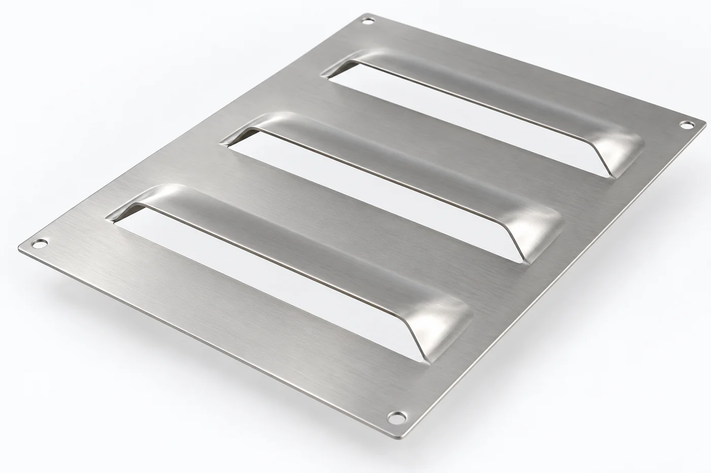
루버 성형은 판재 일부를 절개하고 입체적으로 들어 올려 통풍 입구와 덮개를 함께 만드는 기술입니다. 작은 돌출 형상에도 소재의 늘어남, 금형 지지, 이송 간섭과 완성품의 공기 경로가 연결됩니다.
전자 하우징·장비 커버·제어반 판넬의 일체형 루버를 중심으로 절개선과 연결부, 성형 높이와 피치, 버·스프링백·표면처리, 개구 면적과 실제 통풍량의 차이를 살펴봅니다. 도면에서 정할 기준을 공정 설계와 최종 검사까지 이어서 정리합니다.
형상과 금형
입구·후드·연결부를 구분하고 절개·지지·성형·취출을 연결합니다.
배열과 공정 안정성
소재·높이·피치·이송·후처리를 함께 검토해 형상을 유지합니다.
통풍과 검증 기준
개구 면적과 실제 유량을 구분하고 치수·조립·성능 검사를 정합니다.
01기능과 형상의 정의
루버가 만드는 개구와 덮개
금속 커버에 바람길이 필요할 때 구멍을 크게 뚫는 방법만 있는 것은 아닙니다. 판재 일부를 절개하고 주변 금속과 이어진 채로 들어 올리면 입체적인 입구와 덮개를 함께 만들 수 있습니다. 이것이 판금 루버 성형의 기본 발상입니다. 별도 덮개를 조립하는 대신 한 장의 판에서 통풍을 위한 형상을 얻는 방식입니다.
루버의 역할은 공기가 통과할 길을 마련하면서 입구의 방향과 외관을 함께 정하는 데 있습니다. 후드는 특정 방향에서 내부가 바로 보이는 것을 줄일 수 있지만, 공기의 출입을 한 방향으로만 허용하는 밸브는 아닙니다. 실제 유동 방향은 팬, 압력 차이와 설치 조건에 따라 달라지므로 외관상 입구 방향과 공기 흐름의 방향을 구분해야 합니다.
통풍 구멍과 성형 루버의 선택
| 형식 | 기본 구조 | 함께 검토할 사항 |
|---|---|---|
| 원형·장공 타공 | 판 두께를 관통하는 평면 개구 | 개구율·버·내부 직접 노출 |
| 일체형 성형 루버 | 연결된 판재가 후드와 입구를 형성 | 돌출 공간·성형성·방향·압력 손실 |
| 별도 그릴·필터 | 패널 개구에 다른 부품을 조립 | 장착 공간·밀봉·교환·추가 저항 |
| 밀폐형 방열 구조 | 환기 대신 전도 등으로 열을 전달 | 열 경로·접촉·외함 요구의 별도 설계 |
여기서 다루는 대상은 전기·전자 하우징, 장비 커버와 제어반 판넬 등에 사용하는 판재 일체형 루버입니다. 건축물의 대형 방우 루버나 열교환기 핀의 미세 루버와는 형상, 제조 공정과 평가 조건이 다릅니다. 다른 분야에서 제시한 성능 계수나 규격 값을 같은 이름이라는 이유로 그대로 적용해서는 안 됩니다.
설계의 출발점은 필요한 통풍, 외부 접근 제한, 외관과 설치 공간을 나누어 정의하는 것입니다. 먼저 목적을 정하면 성형 높이를 높일지, 개수를 늘릴지, 별도 필터를 둘지 판단할 근거가 생깁니다. 한 장의 외관 사진만으로 냉각 성능이나 방수·방진 등급을 판정할 수 없으며, 장착 후의 기능 조건을 따로 확인해야 합니다.
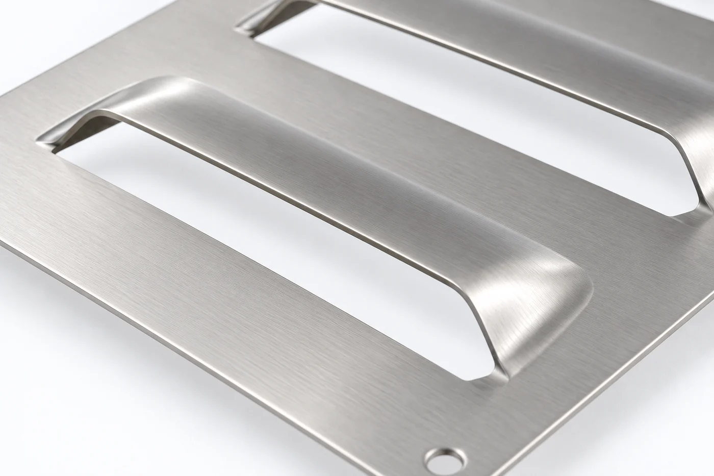
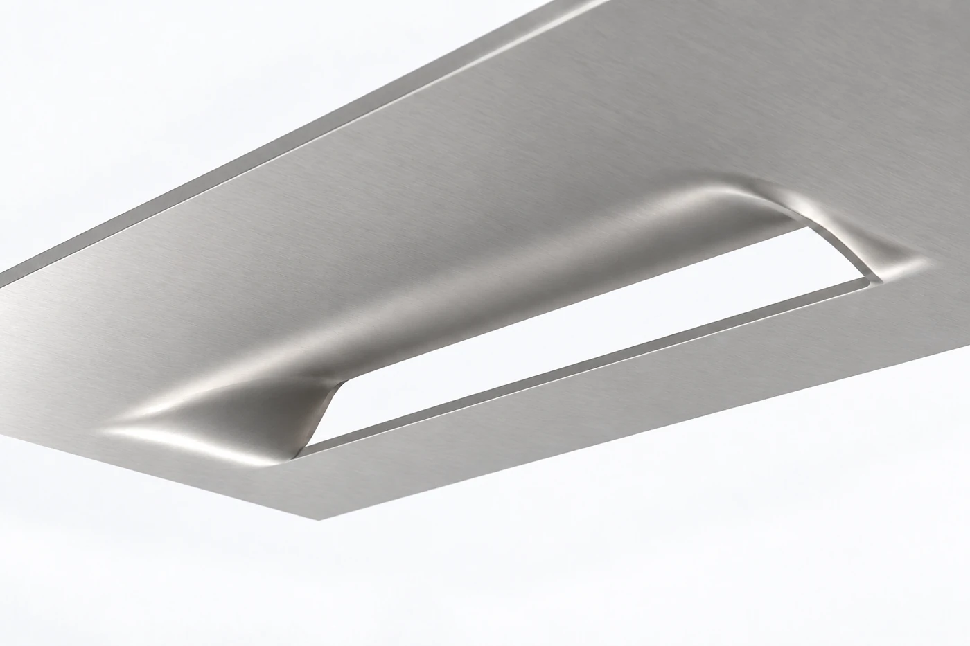
본문의 사진은 형상 이해를 위해 생성한 설명 이미지이며 특정 납품품이나 보유 설비의 실적 사진이 아닙니다. 세 가지 3D는 연결부와 개구, 배열 간격, 공기 통로를 살펴보는 개념 모델입니다. 실제 금형 설계도나 재료 성형 해석, 유동 해석 결과를 대신하지 않으며 수치 예시는 계산 기준을 설명하기 위한 가정입니다.
절개선·후드·측면 연결의 형상
이 글의 대표 형상은 한쪽 긴 가장자리에 입구가 있고 뒤쪽과 양 끝이 주변 판에 이어진 후드형입니다. 앞쪽 절개선이 벌어져 통로가 되고, 뒤쪽 경사면과 양 끝의 성형 영역은 덮개를 지지합니다. 위에서 보면 단순한 돌출부처럼 보여도 단면에서는 공기가 지나는 빈 공간과 금속이 이어지는 부분이 명확히 나뉩니다.
모든 루버가 이 구조인 것은 아닙니다. 양 끝을 여는 형식, 뒤쪽에 곡률을 주는 형식, 공구를 반복 이동하여 길이를 늘리는 연속 루버가 별도로 존재합니다. 따라서 도면에 “루버”라고만 적거나 U자 절개 탭 하나로 모든 구조를 표현하면 제작자가 다른 형상을 이해할 수 있습니다. 절개되는 선과 연결되는 영역을 함께 표시해야 합니다.
성형 높이와 입구 틈의 구분
| 도면 항목 | 정의할 기준 | 잘못 해석하기 쉬운 점 |
|---|---|---|
| 성형 높이 H | 지정 기준면에서 후드의 지정 면까지 | 외측 전체 높이와 내부 틈을 혼용 |
| 입구 틈 g | 완성 상태의 지정 위치에서 실제 빈 간격 | 양 끝의 곡면 때문에 위치별로 달라짐 |
| 길이 L·깊이 B | 절개선·외곽 또는 접선점 등 기준 명시 | 입구 길이와 성형 점유 길이를 동일시 |
| 방향·연결부 | 완성품 외측·입구 방향·남는 연결 영역 | 평판 전개에서 방향이 뒤집힘 |
외측 높이가 같아도 판 두께, 입구 가장자리의 기울기와 모서리 곡률이 다르면 실제 통과 틈은 달라집니다. 높이 하나만 검사하면 후드 형상은 비슷하지만 입구가 덜 열린 부품을 놓칠 수 있습니다. 공기 통과나 접근 제한에 직접 필요한 치수는 별도의 기능 치수로 정하고, 어느 위치에서 어느 방향으로 측정하는지까지 연결하는 편이 좋습니다.
후드가 점유하는 공간은 판의 앞면과 뒷면에서 모두 확인합니다. 외측 돌출부가 주변 커버에 닿지 않더라도 내부 측면의 성형 영역이 배선, 필터 프레임이나 보강대와 간섭할 수 있습니다. 단면도와 조립도에 이 공간을 함께 표시하면 평판 단계에서는 보이지 않던 충돌을 설계 시점에 검토할 수 있습니다.
CAD에서는 완성 형상을 먼저 정의한 뒤 선택한 공구의 절개·성형 방식과 전개 표현을 맞춥니다. 성형 피처가 있다는 이유만으로 일반 굽힘 전개와 동일하게 계산되는 것은 아닙니다. 후드 양 끝에는 굽힘뿐 아니라 국부 늘어남과 재료 유입이 포함될 수 있으므로 공구업체의 형상 정의, 실제 시험 성형과 최종 도면을 같은 기준으로 비교해야 합니다.
02소재와 금형 구조
소재·두께·절단면이 성형을 바꾸는 이유
같은 금형에서도 소재 등급과 공급 상태가 달라지면 성형 결과가 달라질 수 있습니다. 연신 능력, 항복 특성, 가공경화와 표면 상태가 후드의 높이와 끝단 균열, 취출 후 형상에 영향을 주기 때문입니다. 단순히 철·스테인리스·알루미늄으로 구분하는 데서 끝내지 말고 정확한 등급, 질별 또는 조질 상태와 두께 범위를 확인해야 합니다.
판 두께는 구조와 공구 양쪽에 작용합니다. 더 두꺼운 판을 사용하면 절단과 성형에 필요한 조건뿐 아니라 금형 사이에서 재료가 지나가는 간격, 취출 여유와 완성품의 내부 틈이 달라집니다. 특정 두께용 공구에 두꺼운 소재를 넣고 스트로크만 조절하는 방법은 공구와 형상 손상을 일으킬 수 있으므로 허용 범위부터 확인해야 합니다.
재료 선택을 형상 요구와 연결하기
| 재료 검토 | 성형에서 확인할 점 | 완성품에서 확인할 점 |
|---|---|---|
| 저탄소강 계열 | 등급·연신성·표면 및 윤활 상태 | 방청 처리와 절개 가장자리 |
| 스테인리스강 | 강종·가공경화·탄성 회복·공구 마찰 | 표면 흠집·오염·기능 틈 |
| 알루미늄 합금 | 합금·질별·굽힘 및 늘어남의 여유 | 찍힘·변형·후처리 외관 |
| 선도장·도금 판재 | 성형 중 피막의 균열·벗겨짐 | 절단부 노출·보수 기준·접지면 |
후드의 양 끝과 뒤쪽 연결부에는 변형이 고르게 분포하지 않습니다. 높이를 과도하게 키우거나 작은 영역에서 급하게 곡률을 바꾸면 국부적으로 늘어나며 얇아지는 구간이 생길 수 있습니다. 초기 검토에서는 가장 눈에 잘 띄는 중앙 입구뿐 아니라 끝단의 전이 형상과 절개선이 끝나는 위치까지 확대해 살펴야 합니다.
압연 방향도 시험 조건에 포함합니다. 성형 방향에 따른 균열 민감도는 소재와 형상에 따라 달라지며, 한 방향에서 얻은 시험 결과를 방향을 바꾼 배치에 그대로 적용하기 어렵습니다. 네스팅 효율을 위해 부품을 회전한다면 민감한 연결부에서 같은 성형 결과가 나오는지 확인하고 승인한 방향을 전개도와 작업 자료에 남깁니다.
절개 가장자리의 품질은 후속 성형의 입력 조건입니다. 버가 작다는 사실만으로 끝단의 균열 여유가 충분하다고 판단할 수 없고, 레이저 절개와 금형 전단도 가장자리 상태가 다를 수 있습니다. 시제품은 외형 확인에 활용하되 양산에서 사용할 절개 방식과 소재로 다시 성형해 개구, 끝단과 표면을 확인하는 것이 공정 차이를 줄이는 방법입니다.
절개와 성형을 연결하는 금형 구조
루버 공정은 필요한 선을 절개하는 작용과 판재를 입체적으로 변형시키는 작용을 연결합니다. 공구 구성에 따라 한 스트로크에서 절개와 성형을 진행하거나, 미리 절개한 판을 별도 성형 공구로 들어 올릴 수 있습니다. 한 번에 가공한다는 표현만으로 두 방식의 공구와 공정 조건이 같다고 이해해서는 안 됩니다.
금형의 절단부는 입구가 열릴 가장자리를 만들고, 성형부와 상대 지지면은 후드의 단면과 연결부를 유도합니다. 누름·스트리핑 기능은 판재를 지지하고 공구에서 분리하는 역할을 맡습니다. 실제 공구에서는 이 기능이 여러 인서트와 스프링 구조에 나뉘거나 통합되므로 제품 단면만 보고 공구 전체 구조를 역으로 단정하기는 어렵습니다.
절단·지지·성형·취출을 함께 검토하기
| 공정 기능 | 검토할 대상 | 불안정할 때 나타날 수 있는 현상 |
|---|---|---|
| 절개 | 절단부 정렬·간극·마모·끝단 형상 | 버·절개 불균일·끝단 손상 |
| 지지와 위치 결정 | 판의 접촉면·누름·기준 위치 | 끌림·위치 이동·주변 휨 |
| 형상 부여 | 인서트 곡률·깊이·재료 유입 | 높이 편차·박육·주름 |
| 공구 분리·취출 | 스트리핑·복귀·돌출부 여유 | 입구 눌림·걸림·표면 긁힘 |
성형 방향은 완성품의 위아래와 기계 안에서의 위아래를 나누어 표시합니다. 판을 뒤집어 가공하면 같은 외형도 공구 배치와 이송 조건이 달라집니다. 위로 성형할지 아래로 성형할지는 장비의 지지 구조, 스트리핑 방식과 이미 만든 돌출부의 통과 여유를 함께 검토하여 정하며 한 방향이 모든 설비에서 정답인 것은 아닙니다.
프레스의 명판 하중만으로 작업 가능 여부를 판단하지 않습니다. 절개 시점의 부하 변화, 성형 깊이와 스트로크 제어, 스테이션 크기, 공구 높이와 장비의 성형 모드가 함께 맞아야 합니다. 기계와 공구 공급자가 제시한 조건을 확인하고, 초기 시험에서는 취출 후 높이와 입구가 반복해서 유지되는지 측정해 설정을 고정합니다.
아래 모델은 선택한 후드형의 절개선과 연결부가 어떻게 입체 형상으로 바뀌는지 보여 줍니다. 진행 단계는 형상 관계를 쉽게 읽도록 나눈 것으로 실제 펀치의 시간별 운동이나 금속의 변형률을 계산한 결과가 아닙니다. 특히 끝단의 재료 이동과 두께 변화는 실물 시험 또는 검증된 성형 해석에서 따로 확인해야 합니다.
한 장의 판에서 입구와 후드를 만들기
INTERACTIVE 3D한쪽 긴 입구가 열리고, 후방과 양끝은 주변 판재에 이어져 있습니다. 부품을 별도로 붙인 구조가 아닙니다. 판재를 보존해 이동한 개념 형상이며 실제 늘어남·박육·스프링백이나 금형 접촉을 계산하지 않습니다.
03성형 안정성과 배열
성형 높이·곡률·스프링백의 균형
통로를 더 크게 만들기 위해 후드 높이만 올리면 형상은 쉽게 그릴 수 있어도 공정 여유는 줄어들 수 있습니다. 같은 점유 폭 안에서 높이를 키우면 경사와 끝단 전이가 급해지고 주변에서 끌려오는 재료의 양도 달라집니다. 입구를 넓히는 목표와 성형 가능한 형상은 길이, 깊이, 곡률과 소재 조건을 함께 바꾸며 맞춰야 합니다.
작은 반경은 외형을 선명하게 만들지만 모든 소재에 유리하지는 않습니다. 변형이 좁은 영역에 집중되면 표면과 절개 끝단에서 문제가 먼저 나타날 수 있습니다. 반대로 반경을 크게 하면 성형 영역이 넓어져 이웃 홀이나 다른 루버에 접근합니다. 반경은 외관과 균열 여유, 점유 공간을 동시에 조절하는 치수로 다루는 것이 좋습니다.
평균 오차와 공정 변동의 구분
| 관찰 결과 | 먼저 구분할 문제 | 검토 방향 |
|---|---|---|
| 모든 높이가 비슷하게 낮음 | 설정 또는 형상 보정 문제 | 기준·스트로크·공구 형상·탄성 회복 |
| 높이가 계속 흔들림 | 입력 조건의 변동 | 소재 두께·위치·윤활·마모 |
| 중앙은 맞고 끝단만 이상 | 국부 성형 또는 연결부 문제 | 전이 곡률·재료 유입·절개 끝 |
| 금형 안에서는 맞고 취출 후 달라짐 | 제하·스트리핑 영향 | 자유 상태 측정·취출 동작 확인 |
스프링백은 하중을 제거한 뒤 형상이 탄성적으로 회복하는 현상입니다. 따라서 금형이 닫힌 상태의 높이와 완성품 높이를 같은 것으로 취급하지 않습니다. 목표가 자유 상태 형상인지, 조립 지그에 놓였을 때 형상인지도 구분합니다. 검사자가 손으로 눌러 높이를 맞춘 결과는 자유 상태의 치수와 비교할 수 없습니다.
보정량은 재료와 공구, 공정에 종속됩니다. 일반 굽힘의 경험값이나 다른 회사 공구의 추천 각도를 그대로 옮기기보다 실제 소재로 시험하고 평균 편차와 분산을 함께 확인합니다. 한 개의 양품에 맞춰 조건을 바꾸는 대신 같은 조건에서 여러 위치와 연속 부품의 결과를 확인해야 재현 가능한 설정을 찾을 수 있습니다.
이미 균열이나 심한 박육이 생긴 형상을 깊이 조절만으로 정상화하려 해서는 원인을 놓치기 쉽습니다. 형상 자체가 재료에 과도한 변형을 요구하는지 먼저 확인하고 높이, 깊이, 전이 반경이나 공정 분할을 검토합니다. 형상 보정 후에는 입구 크기뿐 아니라 주변 평탄도와 후속 표면처리 뒤 상태까지 다시 확인하는 편이 좋습니다.
피치·남는 폭·주변 여유의 배열 설계
루버를 촘촘하게 배열하면 같은 패널 안에 더 많은 입구를 배치할 수 있지만, 입구와 입구 사이의 거리만으로 제작성을 판단할 수는 없습니다. 각 후드는 뒤쪽 경사면과 끝단 전이부까지 공간을 차지하며 성형 공구도 부품보다 넓은 접촉·지지 영역을 사용할 수 있습니다. 배열은 완성 형상과 공구가 필요한 공간을 나누어 검토해야 합니다.
동일한 방향의 루버를 반복 배치할 때 피치 p를 같은 기준점 사이 거리, 성형 깊이 B를 해당 방향의 점유 길이로 정의하면 남는 기하학적 폭은 p−B로 비교할 수 있습니다. 다만 이 값은 공구 접근성과 재료 유입을 보장하는 최소 폭이 아닙니다. 곡면 경계와 엇갈린 배열, 반대 방향 배치에서는 실제 외곽을 기준으로 다시 확인합니다.
간격의 측정 기준과 경계
| 간격 항목 | 비교할 경계 | 설계 목적 |
|---|---|---|
| 행 사이 간격 | 성형 외곽·공구 접촉 영역 | 이웃 성형의 변형·공구 충돌 검토 |
| 판 가장자리 여유 | 성형 끝단에서 자유 가장자리까지 | 재료 지지·가장자리 휨·취급 |
| 홀·체결부 여유 | 성형 영역에서 기능 홀·좌면까지 | 홀 위치·와셔 착좌·공구 접근 |
| 굽힘·보강부 여유 | 성형 외곽에서 후속 굽힘 영역까지 | 공정 순서·압착·주변 간섭 |
공구 자료에 있는 간격 규칙은 적용 형식을 확인해야 합니다. 어떤 루버 도면은 평탄부를 남기기 위한 판 두께 배수 조건을 제시하고, 다른 전용 공구는 특정 방식의 맞댄 배열을 허용합니다. 서로 다른 조건을 보고 하나를 틀렸다고 판단하기보다 공구 형식, 배열 방향과 평탄도 요구가 같은지 비교해야 합니다. 보편적인 최소 피치 하나로 대체하기 어렵습니다.
예를 들어 설명용 형상에서 성형 점유 깊이가 12 mm이고 피치가 20 mm라면 두 외곽 사이의 기하학적 폭은 8 mm입니다. 피치를 16 mm로 줄이면 4 mm가 남습니다. 이는 단순한 평면 배치 계산이며 어느 쪽이 제작 가능한지 또는 더 튼튼한지는 알려 주지 않습니다. 실제 선택에는 금형 지지, 소재 변형과 패널 고정 조건을 추가해야 합니다.
아래 3D에서는 피치를 바꾸며 후드 외곽과 남는 폭의 관계를 볼 수 있습니다. 패널이 길어지거나 배열 방향이 바뀌면 홀·플랜지·프레임과의 간격도 함께 바뀔 수 있다는 점을 염두에 두어야 합니다. 실제 설계에서는 루버 한 개의 치수보다 전체 패턴의 기준 위치, 가장자리 여유와 기능부 위치를 같이 승인하는 것이 효과적입니다.
배열 피치와 남는 평탄부 살펴보기
INTERACTIVE 3Dw = P − D · D = 2.40 (상대 비율)
피치 P는 반복 위치 사이 거리이고, 평탄부 w는 P에서 성형부의 평면상 깊이 2.40을 뺀 값입니다. 아래 수치는 상대 비율이며 mm가 아닙니다. 조절 범위는 그림의 겹침을 막기 위한 설정으로 최소 제작 간격을 뜻하지 않습니다. 실제 배치는 성형 외곽·끝단·금형 외형·기존 성형부·클램프와의 간섭까지 검토합니다.
04가공 순서와 품질
NCT 가공 순서와 이송 간섭
평판일 때는 자유롭게 이동하던 소재도 루버가 생기면 위아래 공간을 차지합니다. 공구를 피해 다음 위치로 이동하는 동안 돌출부가 다른 다이, 테이블이나 클램프에 걸릴 수 있습니다. 따라서 루버 가공 프로그램은 가공점의 좌표만 나열하는 작업이 아니라 각 단계에서 달라지는 부품 높이와 이동 경로를 관리하는 작업입니다.
일반적인 홀과 외형 가공을 먼저 하고 돌출 성형을 뒤로 보내는 순서는 유용한 출발점이지만 모든 부품에 동일하게 적용되는 규칙은 아닙니다. 외형을 너무 일찍 분리하면 소재 지지가 부족할 수 있고, 모든 성형을 마지막에 몰면 클램프 접근이나 재위치 결정이 어려울 수 있습니다. 장비의 성형 방향과 지지 방식에 맞춰 순서를 결정해야 합니다.
공정 중간 상태와 간섭
| 단계 | 확인할 중간 상태 | 놓치기 쉬운 간섭 |
|---|---|---|
| 평판 준비·일반 타공 | 클램프 영역·기준 홀·소재 방향 | 뒤에 필요한 지지 영역의 선행 제거 |
| 루버 성형 | 이미 성형한 부위와 다음 공구 위치 | 공구 바깥 몸체·주변 다이 접촉 |
| 재위치 결정·외형 분리 | 파지 위치와 부품 지지 | 돌출부 압착·부품 처짐·방향 혼동 |
| 후속 굽힘·조립 | 금형·지그 안의 완성 루버 공간 | 후드가 눌리거나 필터 프레임과 접촉 |
단일 타격 루버와 연속 루버는 가공 순서의 의미도 다릅니다. 연속 루버는 공구를 겹쳐 이동하며 긴 형상을 만들기 때문에 이동량과 진행 방향이 표면의 연속성과 높이에 영향을 줍니다. 제조사가 제시한 반복량은 해당 공구와 조건의 값이므로 다른 길이·소재·형식에 그대로 복사하지 말고 시험 결과를 확인해야 합니다.
루버가 많은 패널은 초기에 만든 부위와 마지막 부위의 형상을 함께 비교합니다. 후반부 가공으로 주변 소재가 움직이면 앞서 합격한 입구의 높이나 패널 평탄도가 바뀔 수 있습니다. 검사 계획에는 첫 성형 직후뿐 아니라 전체 패턴 완료 후와 외형 분리 후의 확인 지점을 포함하면 원인이 생기는 단계를 구분하기 쉽습니다.
소량에서는 준비 시간과 공구 확보, 형상 변경의 유연성이 중요하고 반복 생산에서는 공구 유지, 소재 이용률과 안정적인 취출이 중요해집니다. NCT, 별도 프레스나 프레스 브레이크 공정을 비교할 때도 단순 타격 속도만 보지 않습니다. 가공 전후의 뒤집기, 재파지, 검사와 포장 시간을 함께 계산해야 실제 제작 방식의 차이가 보입니다.
버·균열·평탄도와 표면 품질
루버의 품질은 일정한 줄무늬처럼 보이는지로 끝나지 않습니다. 입구 절개부의 버, 양 끝의 균열, 후드의 비대칭과 패널 휨은 서로 다른 원인과 기능 영향을 가집니다. 외관 불량이라는 한 항목으로 묶으면 공구를 연마해야 할 문제와 소재·형상을 바꿔야 할 문제를 구별하기 어려워집니다.
절개부는 작업자 손이나 배선, 필터와 가까울 수 있으므로 허용 버와 모서리 상태를 용도에 맞게 정합니다. 버 제거 작업 역시 형상을 바꿀 수 있습니다. 입구를 연마하면서 틈이 넓어지거나 얇은 후드가 눌리지 않도록 접근 방법과 지지 방법을 검토하고, 마감 후의 치수를 최종 기준으로 확인해야 합니다.
보이는 현상과 검증할 원인의 연결
| 현상 | 검토할 원인 후보 | 확인 포인트 |
|---|---|---|
| 입구 버·절개 흔적 증가 | 절단부 마모·정렬·간극 변화 | 시작품 대비 변화·버 위치 |
| 끝단 균열·주름 | 국부 변형·전이 형상·재료 유입 | 끝단 확대·소재 방향·윤활 |
| 후드 기울어짐·높이 차이 | 지지·위치·성형·취출 불균형 | 양 끝·중앙의 지정 치수 |
| 패널 휨·국부 들뜸 | 패턴·공정 순서·구속·후처리 | 자유 상태와 조립 상태의 구분 |
높은 부분만 눌러 평평하게 만드는 교정은 루버 입구를 함께 줄일 수 있습니다. 패널 평탄도와 후드 높이가 동시에 필요한 경우에는 어느 영역을 지지하고 어느 영역에 힘을 가할지 정해야 합니다. 기능부를 보호하지 않은 전체 평탄화 작업은 한 가지 검사 항목을 개선하면서 다른 항목을 악화시킬 수 있습니다.
공구에 소재가 달라붙거나 표면에 긁힘이 생기면 윤활, 공구 표면과 소재 보호 상태를 함께 살펴봅니다. 보호 필름을 사용하는 경우에는 성형 중 늘어남이나 찢김, 절개부 잔류물이 다음 공정에 영향을 주는지도 확인합니다. 외관면을 지정해 두면 불필요한 전면 연마보다 기능과 외관에 필요한 부분을 일관되게 관리할 수 있습니다.
불량 원인을 좁힐 때에는 소재 로트, 공구 사용 이력과 발생 위치를 같이 기록합니다. 특정 행에서만 반복되는 문제는 이송·지지 조건과 연결될 수 있고, 생산 수량에 따라 커지는 버는 공구 상태를 확인할 단서가 됩니다. 다만 이런 패턴은 원인을 추정하는 단서이므로 한 가지 현상만으로 결론을 내리지 말고 조건을 통제한 시험으로 확인합니다.
05표면처리와 공기 경로
표면처리·세척·포장 뒤에도 유지할 형상
루버 성형이 끝나도 완성품의 기능은 아직 확정되지 않을 수 있습니다. 후속 도장이나 도금, 세척과 건조를 거치며 입구 가장자리와 후드 아래쪽의 상태가 달라집니다. 도면이 납품 상태를 기준으로 한다면 성형 직후의 높이와 외관만 검사해서는 부족하며 최종 마감 뒤의 개구와 변형을 함께 확인해야 합니다.
도막이나 피막은 좁은 입구의 실제 빈 공간을 줄일 수 있고, 모서리의 축적이나 불균일한 분포가 영향을 줄 수 있습니다. 단순한 평행 틈과 달리 루버 입구에는 기울어진 면과 곡률이 있으므로 명목 두께를 두 배 빼는 계산만으로 최종 통과 공간을 보장하기 어렵습니다. 기능상 중요한 틈은 마감 완료 상태에서 직접 관리하는 편이 명확합니다.
후드 안쪽과 절개 가장자리의 마감
| 후공정 | 루버에서 확인할 위치 | 연결되는 기능 |
|---|---|---|
| 도장·도금 | 입구 가장자리·후드 안쪽·연결부 | 최종 틈·피막 연속성·외관 |
| 세척·헹굼 | 후드 아래·끝단·부품 겹침 영역 | 잔류 오염·배액·건조 |
| 마스킹·접지 처리 | 지정 접촉면과 경계 | 전기적 접속·조립 기준 |
| 운반·포장 | 돌출부와 적층 접촉 위치 | 후드 눌림·긁힘·높이 유지 |
성형 전에 표면처리된 판재를 사용한다면 절개로 노출되는 바탕 금속과 성형부의 피막 상태를 별도로 평가합니다. 반대로 성형 후 처리한다면 후드 안쪽으로 처리액이나 도료가 도달하고 배출되는 조건을 검토합니다. 두 방식은 공정 수만 다른 것이 아니라 가장자리 보호와 외관 관리의 출발점이 다릅니다.
세척은 윤활유 제거와 다음 표면처리의 안정성을 연결합니다. 후드가 아래를 향한 채 겹쳐져 있으면 액이 고이거나 서로 가려지는 부위가 생길 수 있으므로 세척·건조 시의 지지 방향을 확인합니다. 청정도 요구가 있는 경우에는 사진상 깨끗함과 잔류 오염의 합격 기준을 구분하고 필요한 검사 항목을 따로 정합니다.
출하 포장은 후드 꼭대기에 적층 하중이 집중되지 않도록 설계합니다. 적당한 간격재와 지지 위치를 정하고, 부품을 포장에서 꺼낼 때 입구끼리 걸리지 않는지도 확인합니다. 최종 검사 직후에는 맞던 높이가 운송 후 달라지는 문제를 줄이려면 검사와 포장을 별개 업무로 보지 않고 동일한 기능 형상 보존 과정으로 연결해야 합니다.
개구 면적·압력 손실·실제 통풍량
루버의 입구가 커졌다고 통풍량이 같은 비율로 증가하는 것은 아닙니다. 공기는 좁은 통로를 지나며 방향을 바꾸고, 필터·그릴·내부 부품도 흐름에 저항을 더합니다. 팬을 사용하는 장비의 운전점은 팬 성능곡선과 전체 시스템 저항곡선이 만나는 조건에서 정해집니다. 따라서 루버는 패널 단독이 아니라 장비의 공기 경로 안에서 평가해야 합니다.
면적 계산에는 기준이 필요합니다. 패널 정면에 투영한 개구 면적, 입구에서 실제로 열린 면적, 통로 중 가장 좁은 면적은 서로 같지 않을 수 있습니다. 유량 Q를 특정 통과 단면적 A로 나눈 v=Q/A는 그 단면의 평균 유속 관계입니다. 이것은 압력 손실, 유량 계수나 냉각 성능을 자동으로 구하는 식이 아닙니다.
설명용 면적과 유속 계산
| 가정·계산 | 값 | 적용 범위 |
|---|---|---|
| 같은 직사각형 통과면 24개 | 각 50 mm × 2.5 mm | 곡면·끝단을 제외한 단순 가정 |
| 합계 면적 A | 3,000 mm² = 0.003 m² | 동시에 통과하는 병렬 개구의 합 |
| 주어진 유량 Q | 0.012 m³/s = 43.2 m³/h | 루버가 만들어 낸 유량이 아님 |
| 평균 유속 Q/A | 4 m/s | 해당 단면 기준·국부 속도는 별도 |
위 계산의 4 m/s는 각 위치에서 같은 속도가 나온다는 뜻이 아닙니다. 실제 입구는 양 끝의 곡률과 후드의 경사 때문에 유동 분포가 달라질 수 있습니다. 서로 직렬로 놓인 루버와 필터의 면적을 더해서 통과 면적으로 삼는 것도 잘못된 접근입니다. 각 요소의 저항과 상호 간섭을 포함한 압력–유량 관계가 필요합니다.
통풍 경로는 입구에서 열원과 출구까지 이어져야 합니다. 입구와 출구가 너무 가까우면 들어온 공기가 필요한 부위를 충분히 지나지 않고 빠져나갈 수 있습니다. 반대로 큰 개구가 있어도 내부 보강대나 배선이 바로 뒤를 가리면 유효한 흐름이 제한됩니다. 팬의 자유 토출 유량을 조립된 장비의 유량으로 사용하는 것도 피해야 합니다.
아래 모델의 화살표는 후드와 입구를 통과할 수 있는 경로를 설명합니다. 방향을 바꿔 보더라도 풍량이나 압력, 방열량이 계산되는 것은 아닙니다. 실제 성능 확인에는 설치 방향, 팬 제어, 필터 상태와 내부 부품을 반영한 측정이 필요하며 열 검증에서는 주변 온도와 발열 조건, 측정 위치까지 같은 기준으로 비교해야 합니다.
입구 틈새와 공기 경로를 구분하기
INTERACTIVE 3D화살표는 내부에서 외부로 이어지는 가능한 경로만 보여줍니다. 단면에 드러난 입구 틈새와 바닥의 평면 투영 윤곽은 다른 기준입니다. 개구 면적·유량·압력손실·냉각 성능을 계산한 그림이 아닙니다. 실제 흐름 방향과 운전점은 압력차·팬·장치 구조로 정해집니다.
06검증과 제작 승인
치수 검사와 장비 성능 검증의 구분
제작 검사는 부품이 도면대로 만들어졌는지 확인하고, 성능 검증은 그 부품이 장비 안에서 요구 기능을 충족하는지 확인합니다. 높이와 피치가 모두 합격한 패널도 팬·필터·내부 배치가 달라지면 통풍 결과가 달라질 수 있습니다. 반대로 통풍 시험이 한 번 통과했다고 모든 입구의 버와 균열 검사를 생략할 수는 없습니다.
치수 측정에서는 기준면, 지지 위치와 측정 힘을 먼저 정합니다. 얇은 후드는 접촉식 측정 중에 눌릴 수 있으므로 측정 방법이 형상을 바꾸지 않도록 확인해야 합니다. 높이·입구 틈·피치·전체 패턴 위치·패널 평탄도를 구분하고 필요에 따라 광학 측정, 형상 측정이나 전용 게이지를 적용합니다. 장비 이름보다 요구 치수에 맞는 방법인지가 중요합니다.
치수·조립·성능 검증의 범위
| 검증 대상 | 확인할 내용 | 별도 검증이 필요한 부분 |
|---|---|---|
| 루버 치수·형상 | 높이·틈·피치·방향·연결부 | 실제 장비 통풍량과 온도 |
| 조립 상태 | 주변 간섭·체결·필터 장착 | 분진·물·접근에 대한 보호 |
| 통풍·열 | 압력–유량·온도·시험 조건 | 기계적 내구와 전자파 성능 |
| 보호·전자파 요구 | 해당 제품 기준과 전체 조립 조건 | 외관 또는 개구율만으로 추정 금지 |
후드가 빗물을 일부 가리는 방향이라고 해서 방수 등급이 자동으로 생기지는 않습니다. 방진·방수나 접근 방지 요구가 있다면 루버, 필터, 가스켓, 체결부와 배수 구조를 포함한 외함의 조건으로 검토합니다. IEC 60529의 IP 분류도 외함의 보호 등급을 다루므로 루버 단면 하나만 보고 합격을 표시하는 방식은 적절하지 않습니다.
전자파 차폐 역시 별도 설계와 평가 대상입니다. 금속판에 열린 통로가 생기면 개구의 형태와 배치, 주변 접속 조건을 포함해 검토해야 합니다. 차폐용 통풍 부품은 일반 후드형 루버와 다른 구조를 사용할 수 있으므로, 전도성 재료라는 이유만으로 특정 차폐 성능을 주장해서는 안 됩니다. 필요 주파수 범위와 완성 조립체의 요구를 먼저 정합니다.
검사 기록에는 도면 개정, 소재 로트, 공구 또는 공정 식별과 측정 상태를 연결합니다. 첫 제품 승인 이후에도 소재·공구·패턴·후처리가 바뀌면 영향받는 항목을 다시 확인합니다. 변경 전후를 같은 지지와 측정 기준으로 비교하면 원인을 추적하기 쉽고, 도면 합격과 장비 성능 합격의 근거도 서로 명확하게 남길 수 있습니다.
도면·공정·제작 의뢰의 승인 기준
좋은 루버 도면은 완성 형상과 제작자가 필요한 정보를 연결합니다. 소재와 두께, 후드 형식, 높이와 입구 틈, 패턴의 기준 위치, 완성품의 안팎과 입구 방향을 함께 제시합니다. 기능상 필요한 치수와 단순 참고 치수를 구분하면 모든 치수에 불필요하게 같은 공차를 주는 일을 줄이고 실제 검사가 필요한 위치를 명확히 할 수 있습니다.
평면 전개 파일만 전달하면 성형 방향과 최종 높이, 연결부 형상이 빠질 수 있습니다. 전개도와 완성품 3D 또는 단면도를 같은 개정으로 묶고, 표면처리와 최종 검사 상태까지 함께 전달하는 편이 좋습니다. 홀과 플랜지가 가까운 경우에는 단품도 외에 관련 조립 영역을 제공해야 공구와 기능 간섭을 함께 검토할 수 있습니다.
견적·제작 검토에 필요한 자료
| 자료 | 포함할 내용 | 검토 결과 |
|---|---|---|
| 형상·소재 | 도면 개정·재질·두께·성형 방향·연결부 | 공구 형식과 시험 범위 |
| 패턴·조립 | 피치·외곽 여유·체결·내부 간섭 | 가공 순서와 조립 가능성 |
| 마감·품질 | 외관면·버·처리·최종 틈·검사 상태 | 후공정과 합격 기준 |
| 생산·사용 | 시제품·반복 수량·변경 가능성·기능 요구 | 공정 비교와 성능 검증 계획 |
시제품 승인은 보기 좋은 한 장을 고르는 절차가 아닙니다. 합의한 소재와 공정으로 만든 부품에서 주요 치수, 끝단 상태, 전체 평탄도와 실제 조립을 확인하고 필요한 성능 시험을 연결하는 단계입니다. 시험품과 양산품의 절개 방식이나 표면처리가 달라진다면 동일 조건으로 볼 수 있는지 검토하고 차이를 기록해야 합니다.
비용을 줄일 때에는 금형비만 비교하기보다 전체 작업 흐름을 봅니다. 기존 공구에 맞춰 형상을 조정할 수 있는지, 별도 절개와 성형을 나눌지, 한 공정으로 통합할지에 따라 준비와 반복 작업의 비용이 달라집니다. 다만 공구에 맞춘 변경이 입구 면적, 내부 간섭과 외관 요구를 바꾸지 않는지 설계자가 함께 승인해야 합니다.
아이디메탈에 판금 루버 부품을 문의할 때에는 필요한 형상과 사용 목적, 소재·마감, 수량 계획과 검사 요구를 함께 전달하면 검토 범위를 구체화할 수 있습니다. 최종 제작 가능 범위와 공정은 도면 검토 후 협의해야 합니다. 통풍을 위한 작은 돌출 형상도 절개·성형·배열·후처리·장착을 하나로 연결할 때 일관된 품질 기준을 만들 수 있습니다.
English Edition · Creating Air Passages in Sheet Metal: Louver Forming, Geometry and Tool Design
Sheet-metal louver forming slits and raises part of a panel to create a ventilation mouth with an integral hood. Even this small projection connects material deformation, tooling support, transport clearance and the finished equipment’s air path.
Focusing on integral louvers in electronic housings, equipment covers and control-cabinet panels, this article examines slit lines and connections, height and pitch, burrs, springback and finishing, and the difference between opening area and actual airflow. Drawing requirements are followed through process planning to final inspection.
Geometry and tooling
Connect the mouth, hood and retained metal with cutting, support, forming and release.
Layout and process stability
Review material, height, pitch, transport and finishing together.
Airflow and verification
Separate opening area from actual flow and define dimensional, assembly and performance checks.
01Function and geometry
The opening and hood created by a louver
A metal cover that needs an air passage does not necessarily require a larger punched hole. Slitting part of the sheet and raising it while it remains connected to the surrounding metal creates an opening with an integral hood. This is the basic idea of sheet-metal louver forming: a ventilation feature is made in the panel itself instead of assembling a separate cover over an aperture.
A louver provides a passage and defines the orientation and appearance of its mouth. The hood can reduce a direct view into the enclosure from particular directions, but it is not a valve that permits flow in only one direction. Actual flow depends on the fan, pressure difference and installation. The direction in which the mouth faces must therefore be distinguished from the direction in which air passes through it.
Choosing between perforations and formed louvers
| Type | Basic construction | Items to consider |
|---|---|---|
| Round or slotted perforation | A flat aperture through the sheet | Open area, burrs and direct exposure |
| Integral formed louver | Connected sheet forms the hood and mouth | Projection, formability, direction and pressure loss |
| Separate grille or filter | Additional components mounted in a panel opening | Mounting, sealing, replacement and added resistance |
| Closed thermal structure | Heat transferred without a ventilation opening | Separate design of heat paths, interfaces and enclosure requirements |
This article concerns louvers formed integrally in sheet panels for electrical or electronic housings, equipment covers and control cabinets. Large architectural weather louvers and the small louvers in heat-exchanger fins have different geometries, manufacturing processes and test conditions. A performance coefficient or dimensional rule from either field cannot be transferred merely because all three features share the name louver.
Start by separating the requirements for ventilation, restricted external access, appearance and installation space. These priorities establish a basis for deciding whether to increase height, add openings or introduce a separate filter. A photograph of a panel cannot establish cooling performance or an ingress-protection rating; the functional conditions must be checked in the assembled installation.
The photographs are generated editorial illustrations of geometry, not records of a particular delivered product or installed production equipment. The three interactive models explain the connections and opening, layout spacing and air passage. They are conceptual views rather than tool drawings, forming analyses or fluid-flow results. Numerical examples are assumptions introduced to make the calculation basis explicit.
Slit, hood and connected-end geometry
The representative geometry has a mouth along one long edge, with the rear and both ends connected to the surrounding sheet. Separation at the front slit creates the passage, while the sloping rear and formed ends support the hood. From above it may resemble a simple protrusion, but a section reveals the distinction between the open air passage and the portions of metal that remain connected.
Not every louver follows this construction. Open-ended forms, radius-back forms and continuous louvers made through repeated tool movements are distinct alternatives. A drawing labelled only “louver,” or a generic three-sided tab used to represent every version, can lead to a different interpretation in production. Show the cut line together with the regions that remain connected.
Form height and clear mouth
| Drawing item | Reference to define | Common ambiguity |
|---|---|---|
| Form height H | From the stated datum to a specified hood surface | Confusing outside height with inside clearance |
| Clear mouth g | Actual empty gap at a defined location after finishing | Curved ends make clearance position-dependent |
| Length L and depth B | Identify slit, envelope or tangent references | Treating mouth length as the complete formed footprint |
| Orientation and connections | Outside face, mouth direction and retained connections | Reversing orientation in the flat-pattern view |
The same outside height can produce a different clear mouth when sheet thickness, lip inclination or corner curvature changes. Inspecting height alone can miss a part whose overall hood looks correct but whose opening is too restricted. Dimensions directly needed for airflow or access control should be identified separately as functional dimensions, with both measurement position and direction defined.
Check the occupied volume on both faces of the panel. Even if the external projection clears a neighbouring cover, the formed region on the inside may interfere with wiring, a filter frame or a stiffener. Showing the envelope in section and assembly views makes these conflicts visible before production, rather than discovering them after a satisfactory flat-pattern layout has been manufactured.
Define the finished geometry in CAD, then reconcile the flat representation with the selected cutting and forming tool. A forming feature is not automatically developed in the same way as a simple bend. The hood ends may involve local stretching and material draw-in as well as bending. Compare the tool supplier’s geometry definition, trial parts and final drawing using the same reference system.
02Material and tooling
How material, thickness and cut edges affect forming
Even with the same tool, a change in material grade or supply condition can change the result. Ductility, yielding, work hardening and surface condition influence hood height, cracking at the ends and the shape after release. Descriptions such as steel, stainless or aluminium are therefore insufficient by themselves: identify the grade, temper or delivery condition and the permitted thickness range.
Thickness affects both the part and its tooling. A thicker sheet changes cutting and forming requirements, the clearance through which material must move, release allowance and the finished internal opening. Using thicker stock in a tool designed for another thickness, then compensating only with stroke adjustment, can damage the tool or form. Confirm the tool’s approved material range first.
Connecting material selection to the required form
| Material review | Forming checks | Finished-part checks |
|---|---|---|
| Low-carbon steel grades | Grade, ductility, surface and lubrication | Corrosion protection and slit edges |
| Stainless steel | Grade, work hardening, recovery and friction | Surface marks, contamination and clear openings |
| Aluminium alloys | Alloy, temper and bending/stretching allowance | Dents, distortion and finishing appearance |
| Prepainted or coated sheet | Coating cracking or separation during forming | Exposed cut edges, repair criteria and bonding surfaces |
Deformation is not uniform around the hood ends and rear connection. Excessive height or a sharp transition over a short distance can concentrate stretching and local thinning. During initial development, inspect not only the prominent centre of the mouth but also the end transitions and the points where the slit terminates. An attractive centre profile does not establish adequate forming margin at those less visible locations.
Include rolling direction among the trial conditions. Sensitivity to cracking depends on the material and local form, so a result obtained in one orientation may not transfer to a rotated nesting arrangement. If the part is rotated to improve sheet utilisation, check the sensitive connections again and record the approved orientation in the flat pattern and production information.
The slit edge is an input to the subsequent forming operation. A small burr does not by itself establish adequate crack resistance at the ends, and laser cutting can leave a different edge condition from shearing. A prototype can establish geometry, but the intended production material and cutting process should also be trialled to check the opening, end regions and surface condition.
Tooling that connects cutting with forming
Louver production combines creation of the required slit with out-of-plane deformation of the sheet. Depending on the tool, cutting and forming may take place within one stroke, or a separately slit blank may be shaped by a forming tool. Describing either route as a single-hit operation does not mean that the tooling or the necessary process conditions are identical.
The cutting element creates the edge that will open, while the forming surfaces and opposing support guide the hood section and its connections. Holding and stripping functions support the sheet and separate it from the tool. These functions may be distributed among inserts and spring-loaded components or integrated differently. A finished product section alone therefore does not reveal the complete tool construction.
Reviewing cutting, support, forming and release together
| Process function | Review item | Possible sign of instability |
|---|---|---|
| Slitting | Alignment, clearance, wear and slit-end geometry | Burrs, uneven cuts or end damage |
| Support and location | Sheet contact, holding and datum position | Draw-in, positional shift or surrounding distortion |
| Shaping | Insert radii, depth and material movement | Height variation, thinning or wrinkles |
| Release and extraction | Stripping, return and projection clearance | Collapsed mouths, catching or scratches |
Distinguish the finished part’s inside and outside from up and down in the machine. Turning the sheet over changes tooling and transport conditions even when the final shape is unchanged. The forming direction depends on machine support, stripping arrangements and clearance for existing projections. It should be selected for the actual equipment rather than treated as a universally preferred orientation.
Do not judge feasibility from the press nameplate force alone. The change in load during cutting, forming depth, stroke control, station size, tool height and the machine’s forming mode must also be compatible. Confirm the equipment and tool supplier’s conditions, then establish settings by measuring whether height and mouth clearance remain repeatable after the trial parts have been released.
The model below shows how the slit and retained connections of the selected hood form relate to the finished shape. Its stages make the geometry readable; they are not a calculation of punch motion over time or material strain. In particular, material movement and thickness changes around the ends require physical trials or a separately validated forming analysis.
Creating a mouth and hood from one sheet
INTERACTIVE 3DOne long mouth is open while the rear and both ends remain connected to the surrounding sheet. No separate vane is attached. Retained material is displaced schematically; strain, thinning, springback and tool contact are not calculated.
03Form stability and layout
Balancing height, radii and springback
Increasing hood height may look straightforward in CAD while reducing the available process margin. Within the same footprint, a higher form changes the slope, end transitions and the amount of material drawn from the surroundings. A larger opening must therefore be reconciled with manufacturable geometry by considering length, depth, radii and material condition together, rather than changing height in isolation.
A small radius gives a sharply defined appearance but is not suitable for every material. Concentrated deformation may reveal problems at the surface or slit ends first. A larger radius occupies more space and can approach a neighbouring hole or louver. Treat radius as a dimension that influences appearance, forming margin and occupied space simultaneously, not simply as a cosmetic detail.
Average error and process variation
| Observation | Problem to distinguish | Review direction |
|---|---|---|
| Heights consistently below target | Setting or geometry compensation | Datum, stroke, tool shape and elastic recovery |
| Height varies through the run | Changing inputs | Thickness, position, lubrication and wear |
| Centre correct but ends distorted | Local forming or connection issue | Transition radii, draw-in and slit ends |
| Correct in the tool, changed after release | Unloading or stripping effect | Free-state measurement and release motion |
Springback is the elastic recovery that occurs after the load is removed. Height in a closed tool is consequently different from the finished acceptance condition. Also distinguish whether the drawing specifies the free-state part or the shape in a defined assembly fixture. A measurement taken while an inspector manually presses the panel flat cannot be compared directly with a free-state requirement.
Compensation depends on the material, tool and process. Instead of transferring a general bending rule or another tool family’s preferred angle, trial the actual stock and examine both average deviation and variation. Checking several positions and successive parts under the same conditions gives a stronger basis for repeatable settings than adjusting the process to make one selected specimen appear correct.
Once cracking or substantial thinning appears, relying only on depth adjustment can miss the underlying cause. Review whether the geometry demands excessive deformation, then consider height, depth, transition radii or a divided process. After correcting the form, recheck the surrounding flatness and the condition after finishing as well as the size of the opening itself.
Layout design for pitch, remaining web and clearances
Closer spacing allows more mouths within a panel, but the distance between visible openings alone does not establish manufacturability. Each hood occupies space through its rear slope and end transitions, and its tool may need a contact or support region wider than the finished feature. Review the finished envelopes and the space required by the tooling as separate constraints.
For identical louvers repeated in one direction, define pitch p between corresponding reference points and formed depth B as the footprint in that direction. The geometric remaining width can then be compared as p−B. This is not a guaranteed minimum for tool access or material movement. Curved boundaries, staggered layouts and opposite-facing rows require a fresh check of the actual envelopes.
Spacing references and boundaries
| Spacing item | Boundaries to compare | Design purpose |
|---|---|---|
| Between rows | Formed envelopes and tool-contact regions | Interaction between forms and tool collisions |
| To the sheet edge | End of the formed region to the free edge | Material support, edge distortion and handling |
| To holes and fasteners | Formed region to functional holes or seating faces | Hole position, washer seating and access |
| To bends or stiffeners | Formed envelope to later bending regions | Sequence, crushing and nearby interference |
Spacing rules in tooling documents apply to particular configurations. One louver drawing may prescribe a thickness-based web to retain a flat region, while another dedicated tool allows a specified back-to-back arrangement. Compare tool type, orientation and flatness requirements before treating these statements as contradictory. They cannot be reduced to one universal minimum pitch for all louvers.
For an illustrative form occupying 12 mm in the pitch direction, a 20 mm pitch leaves a geometric width of 8 mm between envelopes. Reducing the pitch to 16 mm leaves 4 mm. This is only a planar layout calculation: it does not establish that either arrangement is manufacturable or stronger. Tool support, material deformation and panel mounting conditions remain additional inputs.
The model below lets you compare the hood envelopes and remaining web as pitch changes. Extending a panel or changing the orientation can also change clearances to holes, flanges and frames. For production approval, review the datum position of the whole pattern, edge margins and functional interfaces together instead of approving only the dimensions of an isolated louver.
Array pitch and the remaining flat web
INTERACTIVE 3Dw = P − D · D = 2.40 (relative units)
Pitch P is the distance between repeated locations. Flat web w is P minus the formed feature’s plan depth, 2.40. Values below are relative units, not millimetres. Control limits prevent overlap in this illustration; they are not minimum manufacturing spacing. Real layout must also consider end regions, tooling envelopes, neighbouring forms and clamps.
04Sequencing and quality
NCT sequencing and transport interference
A sheet that moves freely while flat occupies vertical space after louvers have been formed. During travel to the next position, a projection may encounter another die, the table or a clamp. Programming the operation therefore means managing the changing part envelope and travel path at each stage, not simply listing the coordinates at which a tool must strike.
Performing ordinary holes and profiles before protruding forms is a useful starting point, but not a rule that applies identically to every part. Separating the outline too early can remove needed support, while postponing every form can complicate clamp access or repositioning. The final sequence should reflect the equipment’s forming direction, support arrangement and means of retaining the part.
Intermediate process states and interference
| Stage | Intermediate state to review | Easily missed interference |
|---|---|---|
| Flat preparation and ordinary piercing | Clamp area, reference holes and stock direction | Removing support needed by a later operation |
| Louver forming | Existing forms relative to the next tool position | Tool bodies and neighbouring dies |
| Repositioning and separation | Grip locations and part support | Crushing, sagging or orientation errors |
| Later bending and assembly | Clearance for completed louvers in tools and fixtures | Hoods contacting dies or filter frames |
Sequencing also differs between single-hit and continuous louvers. A continuous tool uses overlapping movements to create a longer feature, making progression direction and increment relevant to height and surface continuity. A supplier’s stated increment belongs to that tool and its conditions. Confirm the result before carrying the value over to a different length, material or form family.
For a panel with many louvers, compare features formed early and late in the sequence. Later operations can move surrounding material and alter a mouth or panel flatness that was satisfactory earlier. Inspection after the complete pattern and after profile separation, as well as after the first form, helps identify the stage at which a change appears.
For small batches, preparation, tool availability and flexibility in changing the form can dominate. Repeated production places more emphasis on maintenance, sheet utilisation and reliable extraction. When comparing NCT, a separate press or press-brake tooling, include turning, regripping, inspection and packing time instead of comparing hit rates alone. These supporting operations can materially change the practical choice.
Burrs, cracks, flatness and surface quality
Consistent-looking rows are only one aspect of louver quality. Burrs at the mouth, cracks at the ends, asymmetric hoods and panel distortion have different causes and functional consequences. Combining them into one appearance defect category makes it difficult to distinguish a problem requiring tool sharpening from one requiring changes to the material, geometry or support conditions.
The slit may be close to hands, wiring or filter material, so define the permitted burr and edge condition for the application. Deburring itself can change the shape: abrasion may enlarge the opening, and unsupported handling may flatten a thin hood. Review access and support during finishing and verify the resulting dimensions against the final acceptance condition.
Connecting visible symptoms to causes worth checking
| Symptom | Possible causes to review | Verification point |
|---|---|---|
| Increasing burrs or cut marks | Cutting-edge wear, alignment or clearance changes | Change from start-up and burr location |
| End cracks or wrinkles | Local deformation, transitions or material draw-in | Magnified ends, stock direction and lubrication |
| Tilted or uneven hoods | Unbalanced support, location, forming or release | Specified dimensions at ends and centre |
| Panel bow or local lifting | Pattern, sequence, constraint or finishing | Distinguish free and assembled conditions |
Flattening high regions can reduce the louver mouth at the same time. Where panel flatness and hood height are both functional requirements, define where the panel is supported and where corrective force may act. An unrestricted flattening operation can improve one inspection result while degrading another, particularly if the formed features are not protected.
If material adheres to the tooling or scratches appear, review lubrication, tool surface condition and any protective layer on the stock together. Protective film may stretch, tear or leave material at the slit that affects subsequent work. Defining the appearance face helps production control the relevant areas consistently instead of relying on unnecessary abrasive finishing over the entire panel.
Record material lot, tool history and defect location together when investigating a problem. A defect confined to one row may suggest a transport or support issue, while burr growth through a run points to a useful tool-condition check. These patterns are diagnostic clues rather than proof. Confirm the proposed cause through comparisons in which the relevant conditions are controlled.
05Finishing and air paths
Preserving geometry through finishing, cleaning and packing
The functional condition is not necessarily established when forming ends. Subsequent painting, plating, cleaning and drying can change the mouth edges and surfaces beneath the hood. If acceptance refers to the delivery condition, inspecting height and appearance immediately after forming is insufficient. Verify the clear opening and distortion after the specified finishing operations as well.
A finish can reduce the clear space at a narrow mouth, while local buildup or uneven coverage can change the result further. Unlike a simple parallel gap, the louver entrance includes inclined surfaces and curved transitions. Subtracting twice the nominal coating thickness is therefore not enough to guarantee the usable opening. A directly controlled finished-clearance requirement is clearer for a critical passage.
Finishing the hood underside and slit edges
| Later operation | Louver locations to inspect | Related function |
|---|---|---|
| Painting or plating | Mouth edges, underside and connections | Finished gap, coverage continuity and appearance |
| Cleaning and rinsing | Beneath hoods, at ends and between nested parts | Residual contamination, drainage and drying |
| Masking or bonding preparation | Specified contact faces and boundaries | Electrical connection and assembly requirements |
| Handling and packing | Projections and stacking contact points | Crushing, scratching and retention of height |
With prefinished sheet, assess the substrate exposed by slitting and the condition of the finish in the formed regions. When treatment follows forming, review access to and drainage from the underside of the hood. These routes differ not merely in their operation count but also in how edge protection and appearance are established.
Cleaning links removal of forming lubricant to the stability of the next finishing process. The support orientation matters: nested parts or downward-facing pockets may retain liquid or shield neighbouring surfaces. Where cleanliness is specified, distinguish visual cleanliness from acceptance limits for residual contamination and identify the required inspection method separately.
Arrange packing so stacking loads do not concentrate on the hood crests. Define suitable separators and support points, and check that mouths do not catch during unpacking. Linking inspection and packing as successive steps in preserving the same functional geometry reduces the risk of correct measured heights changing after transport.
Opening area, pressure loss and actual airflow
Increasing the mouth area does not increase airflow by the same proportion. Air changes direction through the restricted passage, while filters, grilles and internal components add resistance. In a fan-driven system, the operating point is set by the intersection of the fan-performance and system-resistance curves. Evaluate the louver within the complete air path rather than treating the panel as an isolated flow guarantee.
Area calculations need a defined reference. Projected open area on the panel face, the actual mouth area and the narrowest section of the passage may differ. Dividing volume flow Q by a chosen flow section A gives its mean velocity, v=Q/A. This kinematic relationship does not automatically provide pressure loss, a discharge coefficient or cooling performance.
An illustrative area and mean-velocity calculation
| Assumption or calculation | Value | Scope |
|---|---|---|
| 24 equal rectangular flow sections | 50 mm × 2.5 mm each | Simplification excluding curved ends |
| Combined area A | 3,000 mm² = 0.003 m² | Sum of parallel openings carrying the flow |
| Given volume flow Q | 0.012 m³/s = 43.2 m³/h | An input, not airflow predicted from the louvers |
| Mean velocity Q/A | 4 m/s | For the stated section; local velocities differ |
The calculated 4 m/s does not mean that every point has that velocity. Curved ends and hood inclination can produce a nonuniform distribution. It is also incorrect to add the areas of a louver and a filter placed in series as though they were parallel passages. Their resistance and interaction must be represented in the pressure–flow relationship.
The air path must connect the inlet to the heat-producing region and outlet. If inlet and outlet are too close, air may leave without passing adequately over the required components. A large opening can also be obstructed immediately behind the panel by a stiffener or wiring. Do not substitute a fan’s free-air rating for the airflow available in the assembled equipment.
The arrows in the model illustrate a possible path through the hood and mouth. Changing the view or direction does not calculate airflow, pressure or heat removal. Performance verification requires measurements representing orientation, fan control, filter condition and internal components. Thermal comparisons additionally need consistent ambient temperature, heat load and temperature-measurement locations.
Separate the mouth gap from the air path
INTERACTIVE 3DArrows show only a possible route from inside to outside. The clear mouth in the section and the plan outline on the base are different references. This is not a calculation of open area, flow, pressure loss or cooling. Actual direction and operating point depend on pressure difference, the fan and the assembly.
06Verification and manufacturing approval
Separating dimensional inspection from system verification
Manufacturing inspection checks conformity to the drawing; system verification checks whether the part fulfils its function in the equipment. A panel with acceptable height and pitch can behave differently when the fan, filter or internal layout changes. Conversely, passing one airflow test does not justify omitting inspection for burrs and cracks at individual openings.
For dimensional inspection, first define the datum, support positions and measuring force. A thin hood may deflect during contact measurement, so confirm that the method does not alter the feature being inspected. Distinguish height, mouth clearance, pitch, overall pattern position and panel flatness. Optical measurement, contour measurement or a dedicated gauge can be selected according to the requirement rather than by instrument name alone.
Scope of dimensional, assembly and performance verification
| Verification target | What to check | What still needs separate evidence |
|---|---|---|
| Louver dimensions and geometry | Height, clearance, pitch, orientation and connections | Installed airflow and temperature |
| Assembly condition | Interference, attachment and filter fit | Protection against dust, water or access |
| Airflow and thermal behaviour | Pressure–flow, temperature and test conditions | Mechanical durability and electromagnetic performance |
| Protection and EMC requirements | Applicable product criteria and full assembly | Cannot be inferred from appearance or open area |
A hood orientation that shelters part of the opening does not automatically create a water-protection rating. Dust, water or access requirements must be evaluated for the enclosure configuration, including louvers, filters, gaskets, fasteners and drainage. IEC 60529 addresses degrees of protection provided by enclosures; an isolated louver section is not sufficient evidence for an IP classification.
Electromagnetic shielding is another separate design and verification task. An opening in a metal panel must be considered together with its geometry, arrangement and surrounding electrical connections. Shielded ventilation products can use constructions different from a general hood louver. Conductive material alone does not establish a particular shielding performance; define the frequency range and assembled-equipment requirements first.
Link inspection records to drawing revision, material lot, tool or process identification and measurement condition. After initial approval, reassess the affected characteristics when material, tooling, pattern or finishing changes. Comparing revisions with the same support and measurement references improves traceability and keeps the evidence for drawing conformity distinct from evidence for equipment performance.
Approval criteria for drawings, process planning and enquiries
A useful louver drawing connects the finished geometry to the information required by production. Include material and thickness, hood family, height and clear mouth, pattern datum position, inside/outside and mouth direction. Distinguishing functional requirements from reference dimensions avoids assigning the same unnecessary tolerance to every feature and clarifies the positions that need actual inspection.
A flat-pattern file alone may omit forming direction, finished height or connection geometry. Supply the flat drawing and finished 3D model or sections at the same revision, together with finishing and final-inspection requirements. Where holes or flanges are close, include the relevant assembly envelope so that both tooling access and functional interference can be reviewed.
Information for quotations and manufacturing review
| Information | Content to include | Result of the review |
|---|---|---|
| Geometry and material | Revision, grade, thickness, direction and connections | Tool family and trial scope |
| Pattern and assembly | Pitch, margins, attachment and internal clearance | Sequence and assembly feasibility |
| Finish and quality | Appearance face, burrs, finish, final gap and inspection state | Later operations and acceptance criteria |
| Production and use | Prototype/repeat volumes, likely changes and functional needs | Process comparison and verification plan |
Prototype approval is not a selection of one attractive panel. It establishes key dimensions, end condition, overall flatness and assembly using the agreed material and process, then connects these checks to the necessary performance tests. If the cutting route or finishing differs between the trial and production parts, review and record whether the conditions are representative rather than assuming equivalence.
Cost comparison should cover the complete workflow rather than tooling price alone. Adapting the form to an available tool, separating slitting and forming, or integrating operations changes both preparation and recurring labour. Any tool-driven geometry change still needs design approval for its effect on opening area, internal clearance and appearance requirements.
For an enquiry to ID METAL, provide the required shape and application together with material, finish, quantity plan and inspection requirements to define the review scope. The feasible manufacturing range and process must be agreed after drawing review. A small raised ventilation feature gains a consistent quality basis when cutting, forming, layout, finishing and installation are treated as connected decisions.
추가 정보
검색엔진용 요약
루버 성형은 판재에 절개와 입체 변형을 주어 연결된 후드와 통풍 입구를 만드는 기술입니다. 개구 형상뿐 아니라 소재·금형·배열·이송·후처리를 연결하고, 완성 치수와 실제 장비의 통풍·열·보호 요구를 구분하여 검증해야 합니다.
핵심 포인트 정리
- 루버의 절개선과 남는 연결부를 명확히 정의합니다.
- 외측 높이와 실제 입구 틈은 다른 치수입니다.
- 소재 등급·두께·공급 상태·압연 방향을 공구 조건과 연결합니다.
- 단일 타격·선절개 후 성형·연속 루버는 공정 조건이 다릅니다.
- 피치와 남는 기하학적 폭만으로 공구 간섭이나 성형성을 보장할 수 없습니다.
- 성형 후 이송·후처리·포장에서 돌출 형상을 보호합니다.
- 개구 면적은 통풍량이 아니며 팬과 시스템 저항을 함께 검토합니다.
- 치수 검사와 조립·열·보호·전자파 검증은 각각의 기준이 필요합니다.
FAQ
루버는 단순한 타공과 무엇이 다른가요?
타공은 판을 관통하는 개구를 만들고, 일체형 루버는 판재를 연결한 채 성형하여 입구와 후드를 함께 만듭니다. 루버는 돌출 공간과 성형·이송 조건까지 검토해야 합니다.
모든 루버가 세 면을 잘라 올린 탭인가요?
아닙니다. 폐단 후드형, 양 끝이 열린 형식, 뒤쪽 곡률을 준 형식과 연속 루버 등 구조가 다릅니다. 절개선과 남는 연결부를 도면에서 지정해야 합니다.
성형 높이와 입구 틈은 같은 값인가요?
다릅니다. 높이의 기준면, 판 두께, 입구 기울기와 끝단 곡률에 따라 실제 통과 틈이 달라집니다. 기능상 중요한 틈은 측정 위치와 방향을 별도로 정합니다.
루버 사이 간격은 판 두께의 몇 배로 정하면 되나요?
모든 공구에 적용되는 하나의 배수는 없습니다. 공구 형식과 성형 외곽, 재료 유입, 평탄도 요구와 가공 순서를 확인하고 해당 공구의 조건으로 검토해야 합니다.
기존 금형에 더 두꺼운 판을 사용해도 되나요?
먼저 금형과 장비의 허용 소재·두께 범위를 확인해야 합니다. 두께 변화는 공구 간격과 하중, 취출, 완성 입구를 바꾸므로 스트로크 조절만으로 대응할 수 있다고 가정하지 않습니다.
입구 면적을 두 배로 하면 통풍량도 두 배가 되나요?
그렇지 않습니다. 팬 성능과 루버·필터·내부 부품의 전체 저항이 운전점을 결정합니다. 면적과 유량의 관계만으로 압력 손실이나 냉각 성능을 보장할 수 없습니다.
아래를 향한 루버면 방수 또는 IP 등급을 보장하나요?
입구 방향만으로 보호 등급을 정할 수 없습니다. 루버·필터·가스켓·체결·배수 등을 포함한 외함과 실제 설치 조건을 해당 요구 기준으로 검증해야 합니다.
제작 검토에 어떤 자료가 필요한가요?
같은 개정의 완성품 도면과 전개 자료, 소재·두께·마감, 입구 방향·패턴·주변 간섭, 수량과 최종 검사 요구를 준비하면 금형과 공정의 검토 범위가 명확해집니다.
관련 주제 확장 설명
프레스 형상과 주변 구조
루버의 국부 형상은 패널의 굽힘·체결·지지 구조와 연결하여 검토합니다.
절개와 최종 마감
절단면·버·윤활·세척·표면처리를 연결하면 최종 입구와 표면 상태의 기준을 유지하기 쉽습니다.
치수와 시스템 성능
도면 합격과 실제 장비의 통풍·온도·보호 요구를 구분하여 검증 계획을 세웁니다.
내부 링크
주변 구조를 검토할 때에는 금속 브라켓의 성형·보강 설계와 공차 누적과 조립성을 함께 확인할 수 있습니다. 절개부는 프레스 금형 클리어런스와 절단면 품질, 후공정은 정밀 금속부품 세척과 청정도와 연결됩니다.
제작 분야는 NCT 정밀 판금 부품 가공에서 확인할 수 있습니다. 도면·소재·마감·수량과 검사 요구는 제품문의·개발의뢰로 전달해 주세요.