
계전기용 동 버스바: 재질·프레스 성형과 접합 품질
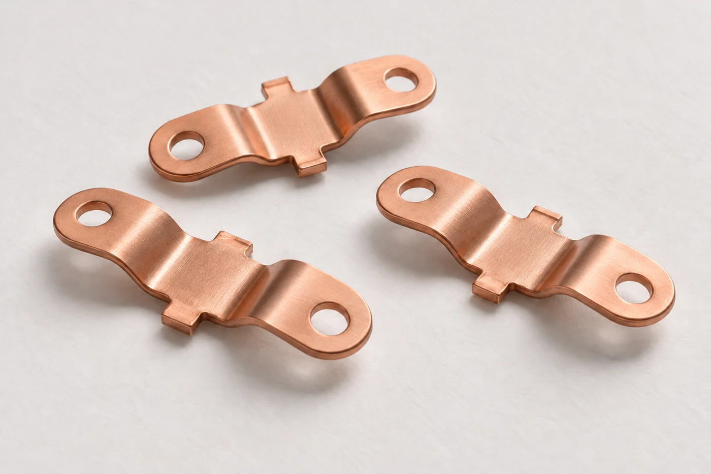
계전기용 동 버스바는 외부 단자와 내부 접점을 연결하며 부하 전류를 전달하는 정밀 통전 부품입니다. 작은 동판 안에 전류 경로, 접점 부착면, 절곡 높이와 절연 지지 위치가 함께 들어갑니다. 전도도가 높은 소재를 선택하는 것에 더해 통전 단면과 접합 저항, 조립 후의 온도상승을 관리해야 안정적인 기능을 확보할 수 있습니다.
동판의 조질은 굽힘과 형상 유지에 영향을 주고, 타발 구멍과 절곡부는 전류가 흐르는 단면을 바꿉니다. 접점을 붙이는 열과 힘은 접합 상태뿐 아니라 접점 높이에도 영향을 줍니다. 소재·성형·접합·표면처리를 기능 치수와 전기·열 검사에 연결해야 완성 계전기에서 낮은 저항과 안정적인 조립 위치를 함께 유지할 수 있습니다.
01계전기용 동 버스바의 역할과 부품 구분
계전기용 동 버스바는 외부 단자와 내부 접점계를 연결하는 동판 기반의 통전 부품입니다. 부하 전류가 지나가는 길을 만들면서 접점의 위치, 절연물에 들어가는 조립 위치, 다른 금속부품과의 접합 위치를 함께 결정합니다. 좁은 계전기 내부에서는 짧은 동판 한 장의 절곡 높이나 구멍 위치도 접점의 맞물림과 방열 경로에 영향을 줍니다.
여기서 다루는 구조는 부하를 개폐하는 전자기식 계전기 내부의 고정 도체와 접점 캐리어입니다. 외부 배전반의 긴 모선과 크기는 달라도 낮은 저항으로 전류를 전달한다는 원리는 같습니다. 다만 소형 부품은 프레스 가공 형상, 수지 하우징과의 조립, 접점 부착부의 정밀도가 더 밀접하게 연결됩니다.
| 부위 | 담당 기능 | 검토할 특성 |
|---|---|---|
| 동 버스바 본체 | 부하 전류 전달과 열 확산 | 전도도·유효 단면·경로 길이 |
| 고정접점 부착부 | 개폐 접점의 위치 지지 | 접합 건전성·높이·평행도 |
| 외부 연결 단자부 | 배선·기판·다른 도체와 연결 | 삽입·체결·납땜 조건과 접속 저항 |
| 절연 지지부 | 통전 부품의 위치 고정과 절연 | 끼움 위치·변형·이격 거리 |
| 가동 접촉편·스프링 | 접점 이동과 접촉력 형성 | 탄성·피로·응력완화 |
동 버스바 전체를 스프링으로 사용하거나, 구리 표면 전체를 개폐 접점으로 취급하지는 않습니다. 전류를 전달하는 본체, 반복적으로 맞닿는 기능 접점, 힘을 유지하는 탄성 부품의 역할을 구분해야 재료와 공정을 정확하게 선택할 수 있습니다. 구조에 따라 한 부품이 두 기능을 겸할 때도 그 두 조건을 각각 검증합니다.
02부하 전류 경로와 은접점의 연결
닫힌 계전기의 전류 경로를 따라가면 입력 단자, 고정 도체, 접합부, 고정접점, 가동접점과 출력측 도체가 이어집니다. 어느 지점의 단면이 좁아지는지, 서로 다른 부품이 만나는 경계가 몇 곳인지 확인하면 발열의 원인을 나눠 볼 수 있습니다. 외형이 넓은 버스바도 접점 아래의 좁은 목이나 작은 접합부에서 전류가 집중될 수 있습니다.
브리지형 가동 접촉판이 두 고정접점을 잇는 이중 차단 구조에서는 두 접촉부가 하나의 전류 경로에 직렬로 연결됩니다. 한쪽만 닿은 상태에서는 정상적인 부하 전류 경로가 완성되지 않습니다. 고정 버스바의 높이와 간격은 양쪽 접촉부가 의도한 위치에서 함께 작동하도록 관리합니다.
통전용 구리와 개폐용 접점재의 기능 분담
구리는 전도도와 열전도도가 높아 전류 전달부에 적합합니다. 반복 개폐에서 상대 접점과 맞닿는 부위에는 부하 조건에 맞는 은계 접점재 등을 배치합니다. 접점재는 접촉저항뿐 아니라 아크 소모, 용착, 재료 이동과 마모를 견뎌야 하므로, 버스바의 구리 등급을 고르는 기준과 동일하지 않습니다.
접점 리벳을 동판 구멍에 끼워 체결하거나, 접점 팁을 용접·브레이징으로 부착하는 구조를 사용할 수 있습니다. 이때 접점재와 동판 사이의 연결은 전류가 흐르는 접합부이면서 반복 충격을 받는 기계적 결합부입니다. 접점 머리가 제 위치에 있는지와 접합 계면이 건전한지는 서로 다른 검사 항목입니다.
코일의 구동 전류와 접점계를 흐르는 부하 전류도 분리해 이해해야 합니다. 코일은 자기력을 만들고 가동기구는 접점을 움직입니다. 동 버스바는 부하 측의 전류를 연결합니다. 두 회로의 전류 경로와 절연 경계를 구분하고, 코일에서 전달되는 열과 가동기구 사이의 간섭이 통전부에 미치는 영향을 검토합니다.
화살표 키로 시점 조절
두 동 버스바는 외부 단자와 내부 접촉부를 이어줍니다. 가동 브리지가 떨어져 있으면 두 버스바 사이의 통전 경로가 열립니다.
동 몸체의 통전 경로와 은합금 기능면의 개폐 위치
03터프피치동·무산소동·동합금의 선택 기준
계전기용 동 버스바의 재료 선정은 전도도에서 출발하지만 접합 공정과 강도까지 이어집니다. 터프피치동과 무산소동은 모두 높은 전도도를 갖는 대표적인 동 재료입니다. 무산소동이라는 이름만으로 전류 용량이나 발열 성능이 크게 달라진다고 판단하기보다, 실제 공급 등급의 전도도와 조질, 후속 열이력을 비교해야 합니다.
| 재료 계열 | 주요 장점 | 함께 확인할 조건 |
|---|---|---|
| 터프피치동 Cu-ETP | 높은 전도도와 성형성을 갖는 통전용 동 | 산소 함유 특성과 고온 환원성 분위기 공정의 적합성 |
| 무산소동 Cu-OF | 높은 전도도, 산소 관련 수소취화 위험을 줄이는 재료 선택 | 등급별 순도·전도도·조질과 접합 열이력 |
| 인탈산동 Cu-DHP·Cu-DLP 등 | 탈산 상태와 가공·접합 특성을 활용 | 잔류 인 함량에 따른 전도도 차이 |
| 고강도 고동합금 | 강도·내연화성 등 기계적 요구에 대응 | 순동 대비 전도도, 성형성, 사용 온도와 열처리 상태 |
전도도에 사용하는 %IACS는 구리 함량의 백분율이 아닙니다. 20°C의 표준 연동 전도도를 기준으로 상대 전도성을 나타낸 값입니다. 100% IACS는 약 58 MS/m에 해당하며, 재료의 보증값과 대표값은 구분해야 합니다. 예를 들어 C11000과 C10200의 소둔 상태 최소 전도도는 모두 100% IACS로 제시되는 반면, 실제 대표값은 이를 넘을 수 있습니다.
고온에서 수소를 포함한 환원성 분위기에 노출되는 공정이라면 산소를 함유한 동의 수소취화 가능성을 검토합니다. 이 문제는 무산소동의 공정 적합성을 판단하는 중요한 이유입니다. 모든 용접이나 브레이징에 터프피치동을 사용할 수 없다는 뜻은 아니며, 열원·분위기·가열 시간과 재료 조합을 함께 정해야 합니다.
탄성을 이용해 접촉력을 유지해야 하는 부위는 순동 버스바와 별도로 검토합니다. 높은 전도도만 보고 스프링용 동합금을 순동으로 대체하면 변형이나 하중 유지 특성이 달라질 수 있습니다. 재료 비교는 같은 두께, 같은 조질, 같은 열이력 조건에서 수행해야 부품 기능과 연결됩니다.
04조질과 판두께가 만드는 성형성·지지 강성
같은 동 등급이라도 연질, 반경질, 경질 등 공급 상태가 달라지면 프레스 금형 안에서의 반응이 달라집니다. 연질은 작은 반경으로 성형하기 유리하지만 취급이나 조립 하중으로 변형되기 쉽습니다. 경질은 형상을 지지하는 항복강도가 높아지는 대신 굽힘 외측의 균열과 스프링백을 더 세심하게 관리해야 합니다.
경도와 탄성강성의 구분
냉간가공으로 경도가 올라갔다고 탄성계수가 같은 비율로 커지는 것은 아닙니다. 같은 형상에서 작은 탄성변형에 대한 강성은 탄성계수와 단면 형상의 영향을 받습니다. 경도와 항복강도의 증가는 영구변형이 시작되는 범위와 관련이 있습니다. 따라서 휘어짐을 줄이는 설계와 소성변형을 방지하는 설계를 구분해야 합니다.
같은 길이와 지지 조건의 직사각 단면을 판두께 방향으로 탄성 굽힘할 때, 굽힘 강성은 폭에는 비례하고 두께에는 세제곱으로 영향을 받습니다. 따라서 두께의 작은 변화도 휘어짐에 크게 반영됩니다. 전류를 위해 두께를 늘리면 기계적 강성도 함께 바뀌므로, 조립 때 상대 부품에 전달하는 힘과 접점 위치 변화까지 확인합니다.
소재 검사에는 두께와 폭 외에 경도 또는 인장 특성, 평탄도, 캠버와 표면 상태를 연결합니다. 캠버는 긴 띠재가 옆으로 휘는 상태로, 연속 금형의 이송과 파일럿 정렬에 영향을 줄 수 있습니다. 재료를 받은 상태에서 기준을 잡고 성형·접합 후의 결과와 비교하면 변동 원인을 찾기 쉽습니다.
접점을 붙이는 동안 들어간 열은 부착부 주변의 가공경화 상태를 바꿀 수 있습니다. 접합 전에는 충분히 단단했던 판이 접합 후 국부적으로 연화되면 접점 높이나 지지부 변형이 달라집니다. 완성 부품의 요구는 원소재 성적서만으로 끝나지 않으며, 후공정까지 지난 상태에서 확인해야 합니다.
05통전 단면과 저항·발열의 연결
균일한 직선 도체의 저항은 R = ρL/A로 정리할 수 있습니다. ρ는 재료의 비저항, L은 전류 경로 길이, A는 통전 단면적입니다. 같은 재료와 온도에서는 길이를 줄이거나 단면을 늘리면 저항이 낮아집니다. 실제 프레스 버스바는 구멍과 단차, 폭 변화가 있으므로 전체 길이에 평균 폭 하나를 적용하는 계산보다 좁은 구간을 나누어 살펴보는 편이 유효합니다.
타발 구멍이나 슬릿은 통전 단면을 줄이는 동시에 전류 흐름을 돌아가게 합니다. 구멍 가장자리, 좁은 목, 급격한 폭 변화에서는 전류밀도가 균일하지 않을 수 있습니다. 접점 부착부를 크게 만들더라도 그 앞 구간이 지나치게 좁으면 전체 통전 성능을 충분히 개선하지 못합니다.
작은 접합 저항의 의미
계산 관계를 살펴보기 위해 20°C, 100% IACS, 길이 25 mm, 단면 5 mm²의 균일한 직선 도체를 가정하면 저항은 약 0.086 mΩ입니다. 여기에 30 A가 흐를 때 도체 자체의 손실은 P = I²R에 따라 약 0.078 W입니다. 같은 경로에 0.5 mΩ의 접합 저항이 추가되면 그 접합부만의 손실은 0.45 W가 됩니다. 이 수치는 치수와 저항의 영향을 비교하는 계산 예이며 제품 정격을 뜻하지 않습니다.
따라서 버스바를 두껍게 만드는 것만으로 접합부의 문제를 해결할 수는 없습니다. 본체 저항, 접점 부착부 저항, 맞닿는 접점의 저항, 외부 단자 접속 저항을 구간별로 나누어 관리해야 합니다. 측정 구간이 달라지면 같은 부품의 저항값도 달라지므로 도면과 검사 기준에 전압 검출 위치를 함께 정합니다.
허용 전류를 일정한 A/mm² 값 하나로 정하면 내부 공간과 방열 조건의 차이가 사라집니다. 전류 파형과 통전 시간, 주위 온도, 수지 하우징, 단자와 배선으로 빠지는 열까지 포함해 온도상승을 검증해야 합니다. 교류에서는 주파수와 배치에 따른 표피·근접 효과도 검토 대상이며, 직류 저항 계산만으로 모든 조건을 대표할 수는 없습니다.
06타발·절곡·코이닝의 프레스 공정 설계
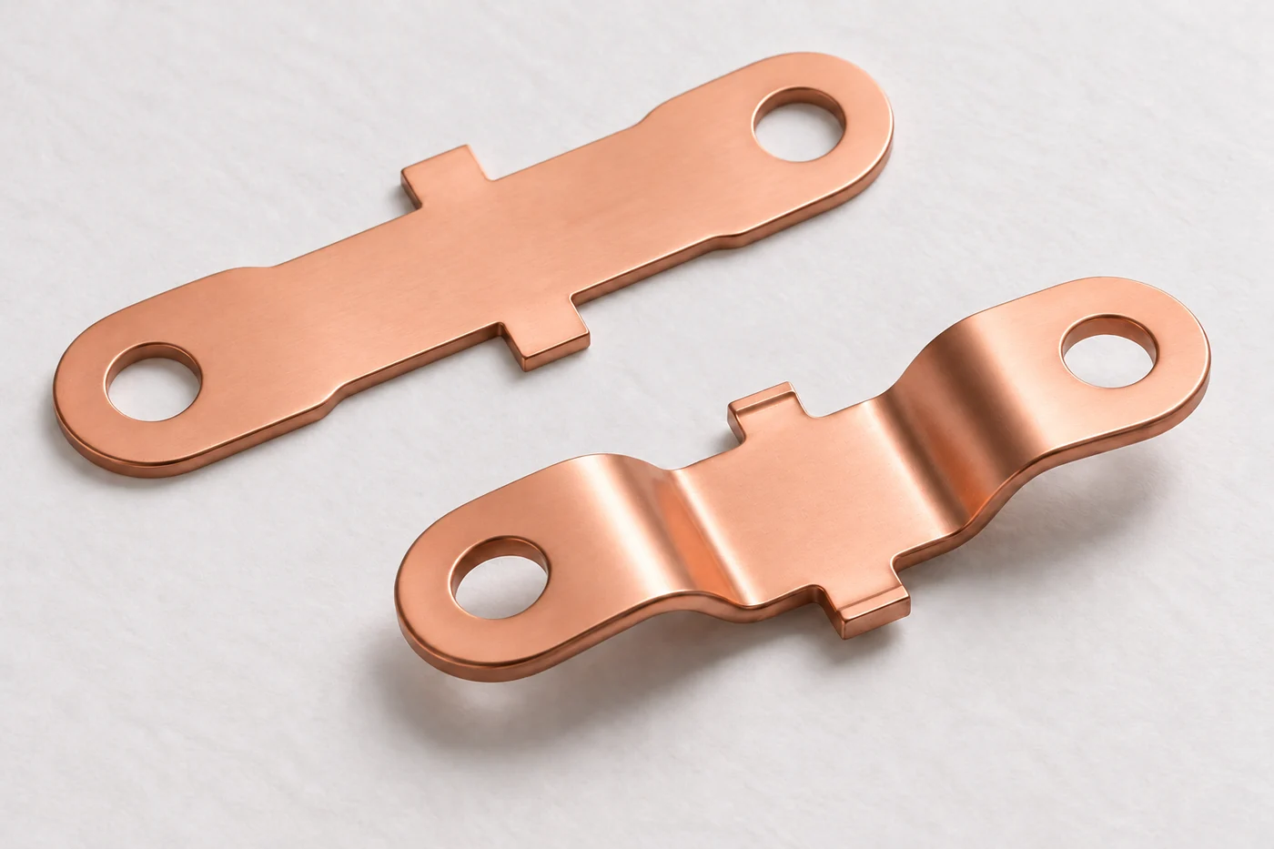
계전기용 동 버스바의 프레스 공정은 외곽과 구멍을 만드는 타발, 높이와 방향을 만드는 절곡, 필요한 기능면을 보정하는 공정으로 구성합니다. 작업 순서는 접점 부착 위치와 최종 조립 기준을 유지하도록 정합니다. 마지막에 구멍 하나를 추가하는 변경도 이미 성형된 부품의 지지와 뒤틀림에 영향을 줄 수 있습니다.
절단면과 굽힘 외측의 연결
타발면에는 눌림부, 전단면, 파단면과 버가 생깁니다. 동의 조질, 판두께, 금형 간극과 날끝 상태에 따라 이 분포가 달라집니다. 버가 접합면이나 절연물 쪽으로 향하면 들뜸, 스크래치와 금속 이물의 원인이 됩니다. 필요한 버 방향과 허용 상태를 정하고, 제거 공정이 기능 치수와 접점 부착면을 손상시키지 않도록 관리합니다.
절곡부는 내측 반경 R과 두께 t의 비율인 R/t, 굽힘축과 압연방향의 관계, 절단 가장자리의 상태를 함께 검토합니다. 높은 연신율만으로 작은 반경의 굽힘을 보증할 수는 없습니다. 소재 자료에서 굽힘 방향을 정의한 방식을 확인하고 실제 부품 방향에 맞춰 적용해야 합니다.
홀이나 슬릿을 굽힘선에 너무 가깝게 놓으면 성형 중 구멍이 늘어나거나 조립 기준이 이동할 수 있습니다. 반대로 그 위치를 무조건 멀리 옮기면 전류 경로와 패키지 배치가 바뀝니다. 전개 형상, 성형 순서와 지지 위치를 함께 조절해 통전 단면과 위치 정밀도를 확보합니다.
코이닝이나 리스트라이크는 접점 받침면과 높이를 다듬는 데 활용할 수 있습니다. 그러나 눌러서 반듯해 보이게 만드는 과정이 국부 두께 감소나 잔류응력을 추가할 수 있으므로, 평탄도와 함께 해당 구간의 두께와 표면 상태를 확인합니다. 금형 보정은 외관보다 최종 조립 기준에서의 위치 재현성을 목표로 해야 합니다.
화살표 키로 시점 조절
관통공과 외곽 형상을 타발한 평판입니다. 구멍 위치를 전개도에 배치할 때 굽힘부와의 거리, 절단면 방향과 접합면의 폭을 함께 정합니다.
관통공이 있는 동 판재의 연속 Z절곡과 성형 후 접합면 위치
07접점 높이·절연 간격·조립 공차의 관리
접점 캐리어를 겸하는 동 버스바는 외부 단자와 고정접점 사이의 위치를 연결합니다. 이때 절곡 높이는 단순한 외형 치수가 아니라 가동접점과 만나는 위치를 정하는 기능 치수입니다. 버스바 두께, 절곡 각도, 접점 높이, 접합층과 절연 지지부의 공차가 같은 방향으로 누적될 수 있습니다.
부품 도면의 기준은 실제로 하우징에 앉는 면과 위치를 잡는 구멍·턱에서 출발해야 합니다. 공중에 떠 있는 끝단만 눌러 측정하면 검사값은 맞아도 조립 상태가 재현되지 않을 수 있습니다. 고정 지그의 눌림과 측정 하중이 얇은 동판을 변형시키지 않는지도 확인합니다.
공간거리와 연면거리의 구분
공간거리는 서로 절연해야 하는 도전부 사이의 공기 중 최단거리이며, 연면거리는 절연물 표면을 따라가는 최단거리입니다. 버스바의 절곡이나 버, 도금 후 외형, 하우징 안착 상태가 이 거리에 영향을 줍니다. 필요한 값은 사용 전압, 과전압 조건, 오염도와 절연 재료 등 해당 설계 조건에 연결해야 합니다.
가동부와 가까운 동 버스바는 열린 상태와 닫힌 상태 모두에서 간섭을 확인합니다. 조립 후 금속부가 미세하게 휘거나 열로 위치가 변할 수 있으므로 단품의 정지 치수만으로 판단하지 않습니다. 접점 간격과 오버트래블, 접촉력은 계전기 기구의 요구이며 버스바의 치수 관리는 그 요구를 안정적으로 재현하는 역할을 합니다.
인서트 사출로 고정하는 구조에서는 사출 압력에 대한 지지, 수지 수축과 금속 위치의 변화, 수지와 맞닿는 모서리 상태를 함께 살펴야 합니다. 금속 치수가 정확하더라도 조립이나 사출 단계에서 위치가 틀어지면 접점 정렬과 절연 조건이 달라집니다.
08리벳팅·용접·브레이징 접합부의 설계
계전기 내부의 접합 방식은 붙이는 대상에 따라 달라집니다. 동 버스바에 접점 리벳을 체결하는 작업, 은계 팁을 부착하는 작업, 별도의 동 도체나 유연 연결부를 연결하는 작업은 같은 접합 문제로 취급할 수 없습니다. 전기 저항, 기계적 강도, 열 영향과 최종 높이를 동시에 만족하는 방식을 선택해야 합니다.
| 접합 방식 | 확보해야 할 기능 | 중점 확인 항목 |
|---|---|---|
| 리벳팅·코킹 | 접점 또는 연결부의 기계적 고정과 통전 | 구멍·다리 맞춤, 성형량, 들뜸·회전, 판 변형 |
| 저항용접·프로젝션 용접 | 국부 가압·가열을 통한 접합 | 재료 조합, 전류·시간·가압력, 유효 접합부 |
| 브레이징 | 용가재를 이용한 접점 팁의 접합 | 젖음, 접합층, 미접합부, 잔류물과 열 변형 |
| 레이저 등 국부 용접 | 설계된 영역에서 금속 연결 | 흡수·입열, 위치, 용입과 기공, 주변 열 영향 |
| 나사·클램프 체결 | 유지되는 면압으로 도체 연결 | 평탄도, 체결력, 마찰 조건, 열·진동 후 안정성 |
리벳팅에서는 머리를 충분히 퍼뜨렸다는 외관만으로 낮은 접합 저항을 보증하지 않습니다. 구멍과 다리의 관계, 성형 중 접촉 상태, 뒤쪽 받침과 판의 변형이 모두 영향을 줍니다. 후면 성형 높이와 부품 회전 여부를 확인하고 필요에 따라 전단·인발 또는 회전 저항 시험을 연결합니다.
구리는 전기와 열을 잘 전달하므로 저항용접에서는 원하는 위치에 열을 집중시키는 설계가 중요합니다. 접합부 돌기, 전극과 가압 조건, 접점재 뒷면의 구성에 따라 공정 창이 달라집니다. 은계 접점재의 종류와 복합 구조를 구분하고, 용접 가능성을 조성명 하나로 단정하지 않습니다.
겹침 접속부의 면압과 열이력
겹침부를 볼트로 고정하는 구조에서는 볼트가 동판 사이의 면압을 유지하고 전류는 주로 겹친 동판의 접촉 계면을 통과하도록 설계합니다. 조임 토크만 같아도 마찰이나 표면 상태가 다르면 체결력이 달라질 수 있습니다. 과도한 압력으로 동판을 눌러 변형시키기보다, 지지 면적과 면압 분포 및 열사이클 후의 유지 상태를 함께 평가합니다.
열을 이용한 접합은 접점 받침면의 평탄도와 주변 동판의 조질에도 영향을 줍니다. 접합 직후의 강도뿐 아니라 온도 변화와 반복 작동 뒤의 저항 변화를 확인해야 합니다. 접합 면적이나 내부 결함을 평가할 때는 단면 관찰과 기계·전기 시험의 결과를 함께 해석합니다.
화살표 키로 시점 조절
두 동 부품의 겹침면이 통전 접합부를 이룹니다. 볼트와 너트는 와셔를 통해 가압력을 전달하며, 접합면의 평탄도와 청정도를 먼저 확보합니다.
동 버스바 겹침면의 밀착과 볼트·와셔·너트의 가압 경로
09도금·세정·표면 상태의 기능별 관리
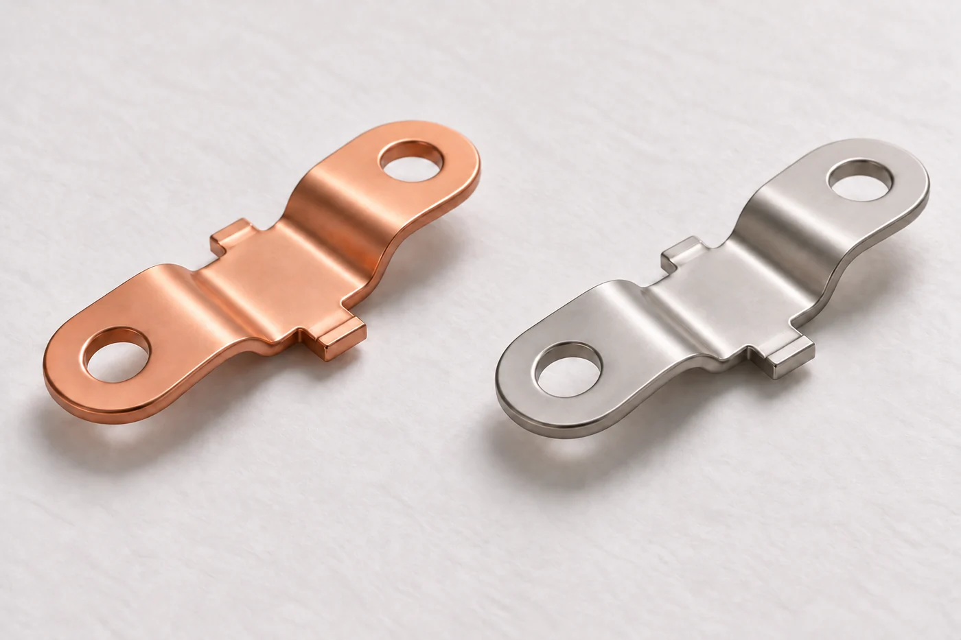
동 버스바의 표면처리는 통전부 전체를 한 가지 조건으로 덮는 작업으로 끝나지 않습니다. 외부 접속면, 접점 부착면, 절연물에 삽입되는 부분은 요구가 다릅니다. 도금이나 보호처리의 영역과 접합 공정 전후 순서를 정해야 산화 억제, 납땜성, 접속 안정성과 조립 치수를 함께 관리할 수 있습니다.
주석은 접속 단자의 표면 기능과 납땜성을 위해 검토할 수 있으며, 은은 접촉부의 전기적 특성에 맞춰 선택할 수 있습니다. 니켈은 공정에 따라 하부층이나 표면층으로 사용됩니다. 이 선택은 상대 재료, 접촉력, 온도와 환경에 따라 달라집니다. 도금 색깔만 보고 은접점이나 내아크 기능층이라고 판단해서는 안 됩니다.
도금 두께와 치수의 연결
균일하게 양면에 두께 δ의 도금이 형성되면 판의 전체 두께는 대략 2δ만큼 증가합니다. 구멍 내벽까지 같은 두께로 도금된 경우 구멍 지름은 대략 2δ만큼 줄어듭니다. 실제 전류 분포와 형상에 따라 가장자리와 오목한 곳의 두께가 달라질 수 있으므로, 평균값뿐 아니라 기능 위치별 두께를 확인해야 합니다.
선도금 판재를 타발하면 절단 가장자리에는 모재가 노출될 수 있습니다. 성형 후 도금하면 구멍과 모서리의 분포, 치수 변화와 후세정이 중요해집니다. 어느 순서가 적합한지는 완성품의 접속면과 부식 환경, 접합 공정에 맞춰 판단합니다. 도금층 위에서 용접하는 경우도 그 층을 포함한 공정 검증이 필요합니다.
프레스유와 세정 잔류물, 연마재와 금속 입자는 접점계로 이동하거나 접합을 방해할 수 있습니다. 세정 후에는 잔류물 기준, 건조 상태와 재오염을 관리합니다. 밝고 균일한 외관은 유용한 검사 단서지만 낮은 저항이나 접합 건전성을 입증하는 측정값을 대신하지는 않습니다.
10온도상승·열팽창·반복 통전의 해석
동 버스바의 발열은 전류와 저항이 만드는 열과 외부로 빠져나가는 열의 균형으로 결정됩니다. 구리는 열을 잘 전달하지만 좁은 하우징 안에서 열을 최종적으로 방출할 곳이 부족하면 온도가 올라갑니다. 계전기 코일, 인접 접점과 기판에서 발생한 열도 부품 주변 온도에 영향을 줍니다.
연속 통전 조건에서는 충분한 시간 뒤의 온도 안정 상태를 확인하고, 반복 통전 조건에서는 켜짐·꺼짐 시간과 냉각 구간을 재현합니다. 같은 실효전류라도 짧은 펄스와 장시간 통전은 온도 이력과 최대 온도가 다를 수 있습니다. 버스바 단품을 공기 중에서 시험한 결과를 밀폐 조립체에 그대로 적용하지 않습니다.
열이 위치와 체결력에 미치는 영향
동 버스바와 수지 지지부, 강재 체결부는 열팽창 특성이 서로 다릅니다. 구속된 상태에서 온도가 바뀌면 위치 변화뿐 아니라 접합부의 하중도 변할 수 있습니다. 이때 단자 위치, 접점 높이와 접합 면압을 함께 살피면 전기적 저항 변화와 기계적 변형의 관계를 설명할 수 있습니다.
구리의 저항은 온도 상승에 따라 증가하므로 초기 상온 저항만으로 뜨거워진 상태를 대표할 수 없습니다. 일정 전류에서 저항이 증가하면 손실도 증가합니다. 주변 방열과 재료 상태가 연결된 문제이므로, 부품 단면 확대나 표면처리 하나의 효과를 분리해 과장하지 않아야 합니다.
단락이나 큰 돌입전류에서는 순간 발열과 전자기력이 추가됩니다. 버스바 지지부와 접합부가 그 하중을 견디는지 검토해야 하지만, 동 버스바가 두껍다는 이유만으로 계전기의 차단 능력이 보증되지는 않습니다. 통전 능력과 접점의 개폐 능력은 서로 다른 요구이며 해당 계전기와 부하 조건에서 평가합니다.
11치수·접합·전기 특성을 연결하는 검사
계전기용 동 버스바 검사는 소재 확인, 기능 치수, 접합 건전성, 전기·열 특성을 서로 연결해야 합니다. 치수 검사에 합격해도 접합 계면이 불완전할 수 있고, 낮은 초기 저항만으로 열·진동 후의 안정성을 판단할 수는 없습니다. 단품 검사와 완성 조립체 평가의 역할을 나누어 운영합니다.
| 검사 영역 | 확인 항목 | 결과의 연결 |
|---|---|---|
| 소재·조질 | 재료 식별, 두께, 전도도, 경도 또는 인장 특성 | 입고 로트와 성형·열이력 추적 |
| 성형 치수 | 접점 높이, 굽힘 각도, 구멍 위치, 평탄도, 버 | 조립 기준면에서 기능 위치 확인 |
| 접합부 | 회전·들뜸, 접합층·미접합부, 전단 또는 인발 특성 | 단면 관찰과 기계적 결과 비교 |
| 전기 특성 | 정해진 구간의 4선식 저항과 전압강하 | 측정 위치·온도·전류의 일치 |
| 열·반복 내구 | 온도상승, 열사이클 후 저항, 작동 후 위치 | 초기값과 사용 조건 후 변화를 비교 |
4선식 측정의 경계 설정
낮은 저항은 전류를 흘리는 선과 전압을 읽는 선을 분리하는 4선식으로 측정합니다. 전압 검출점을 어디에 두는지가 측정 대상의 경계를 정합니다. 접합부 바로 양쪽에 검출점을 두면 접합 평가에 가깝고, 계전기 외부 단자에서 읽으면 내부 도체와 접점의 저항이 함께 포함됩니다.
측정 전류가 너무 작으면 신호가 기기의 분해능과 잡음에 묻힐 수 있고, 너무 크거나 오래 흐르면 자기발열로 상태가 변할 수 있습니다. 이종 금속 접속에서 생기는 열기전력도 저전압 측정에 영향을 줍니다. 필요한 경우 전류 반전 측정을 사용하고, 시험 순서와 안정화 시간을 정해 비교 조건을 맞춥니다.
열화상으로 동 표면을 볼 때는 낮은 방사율과 주변 반사의 영향을 확인합니다. 반짝이는 면의 색이 실제 최고온도를 그대로 뜻하지 않을 수 있습니다. 열전대 등 접촉식 측정과 비교하거나 검증된 방사율 조건을 사용하고, 측정 자체가 작은 부품의 방열을 크게 바꾸지 않는지 살펴야 합니다.
12공정 순서와 양산 변동의 관리
일반적인 제조 흐름은 소재 확인, 이송·타발, 절곡·보정, 세정, 접점 또는 연결부 접합, 표면처리와 최종 검사로 구성할 수 있습니다. 실제 순서는 선도금 여부와 접합 방식에 맞춰 바뀝니다. 공정도를 정할 때 각 단계가 다음 단계의 기준면과 표면에 어떤 영향을 남기는지 함께 표시해야 합니다.
연속 금형에서는 소재 두께와 캠버, 이송 위치, 파일럿과 금형 마모가 형상의 반복성에 영향을 줍니다. 접합 공정에서는 위치, 가압 상태와 열입력의 변화가 완성 높이나 저항으로 이어질 수 있습니다. 최종 불량만 모으기보다 앞 단계의 관리값을 완성품 결과와 연결해야 원인을 구분할 수 있습니다.
관리 항목을 기능 치수에 연결
접점 높이, 최소 통전 폭, 굽힘 후 구멍 위치와 접합면 평탄도처럼 기능을 직접 좌우하는 항목을 우선 선정합니다. 공정능력지수는 측정계가 적절하고 공정이 안정된 상태에서 해석해야 합니다. 모든 치수에 같은 관리 빈도를 적용하기보다 금형 마모나 소재 변경에 민감한 항목을 구분하는 편이 효과적입니다.
재료 등급이 같아도 조질, 표면처리, 접합 조건이 바뀌면 재평가 범위가 달라집니다. 특히 외형을 유지한 채 공급 재료나 열공정을 바꾸는 경우에는 전도도와 강도, 성형 위치를 다시 연결해 확인합니다. 변경 이력은 원소재 로트, 생산 금형, 접합 조건과 검사 결과를 이어서 추적할 수 있어야 합니다.
작은 동 버스바는 보관과 이송 중에도 쉽게 찍히거나 휘어질 수 있습니다. 접점 부착면과 조립 기준면이 서로 충돌하지 않도록 포장 방향을 정하고, 세정된 부품이 다시 오염되지 않게 취급합니다. 출하 상태는 마지막 가공 직후의 품질을 실제 조립 현장까지 유지하는 공정의 일부입니다.
13동 버스바 제작 검토를 위한 도면과 요구 조건
제작 검토는 버스바 외형 도면과 함께 계전기 안에서의 역할을 확인하는 단계에서 시작합니다. 단순 연결 도체인지, 고정접점을 지지하는 부품인지, 외부 연결 단자를 겸하는지에 따라 관리해야 할 면과 치수가 달라집니다. 상대 부품과 조립 단면을 함께 보면 공차와 공정의 우선순위가 분명해집니다.
| 입력 정보 | 구체화할 내용 |
|---|---|
| 부품 기능 | 전류가 들어오고 나가는 위치, 접점·단자·절연 지지와의 관계 |
| 재료 | 동 등급, 조질, 두께, 전도도와 기계적 요구 |
| 형상과 기준 | 조립 기준면, 접점 높이, 굽힘·구멍 위치, 버 방향 |
| 접합과 표면 | 상대 재료, 접합 방식, 처리 영역과 완성 후 치수 |
| 통전·열 조건 | 연속·반복 전류, 돌입 특성, 주위 온도와 방열 경로 |
| 검사와 승인 | 전압 검출점, 저항·온도상승 기준, 기계·내구 평가와 변경 관리 |
이 조건을 연결하면 높은 전도도를 유지하면서 필요한 성형성과 지지 강성을 갖춘 재료를 선택할 수 있습니다. 또 접점 부착부와 외부 접속부의 저항을 구분하고, 절곡 높이와 조립 공차가 완성 계전기의 기능에 미치는 영향을 검토할 수 있습니다.
계전기용 동 버스바의 품질은 동판 자체의 순도나 표면 광택 하나로 결정되지 않습니다. 전류가 흐르는 단면, 접점과 연결되는 계면, 조립 위치를 유지하는 형상과 열이력이 함께 완성도를 만듭니다. 소재·프레스·접합·표면·검사를 하나의 기능 요구로 연결하는 것이 안정적인 통전 부품 제작의 핵심입니다.
Copper Busbars for Relays: Materials, Stamping and Joint Quality
A relay copper busbar is a precision conductor linking an external terminal with the internal contact system. Its compact sheet geometry combines the current path, contact seat, formed height and insulating-support location. High-conductivity stock is only the starting point: conducting section, joint resistance and assembled temperature rise must also be controlled.
Temper influences bending and shape retention, while pierced holes and formed regions change the conducting section. Heat and force during contact attachment affect both the joint and contact height. Linking material, forming, joining and surface control to dimensional and electrical/thermal inspection supports low resistance and stable positioning in the assembled relay.
01Functions and Boundaries of a Relay Copper Busbar
A relay copper busbar is a sheet-based conductor linking an external terminal with the internal contact system. It establishes the load-current path while locating the contact, insulating support and joining interfaces. In a compact relay, a small change in bend height or hole position can affect contact alignment as well as heat flow.
The focus here is the stationary conductor and contact carrier inside an electromechanical relay that switches a load. It shares the low-resistance conduction principle of a distribution busbar, but compact relay parts couple stamped geometry, molded-housing assembly and contact attachment much more closely.
| Region | Function | Properties to evaluate |
|---|---|---|
| Copper body | Carry load current and spread heat | Conductivity, effective section and path length |
| Fixed-contact seat | Locate the switching contact | Joint integrity, height and parallelism |
| External terminal | Connect to a wire, PCB or another conductor | Insertion, fastening or soldering conditions; joint resistance |
| Insulating support | Locate and isolate the live part | Fit, deformation and insulation distances |
| Moving member or spring | Move contacts and establish force | Elastic response, fatigue and stress relaxation |
The entire busbar is not automatically a spring, and its bare copper surface is not automatically the switching contact. Separating conduction, contact-interface and elastic-support functions makes material and process selection more precise. If a single part combines two functions, both must be verified.
02The Load Path and Its Connection to Silver-Based Contacts
Tracing a closed relay reveals the input terminal, fixed conductor, attachment joint, fixed contact, moving contact and output conductor. Identifying constrictions and interfaces helps separate possible heat sources. A broad-looking busbar may still concentrate current at a narrow neck below the contact or at a small attachment region.
In a double-break arrangement, a moving bridge joins two fixed contacts and the two interfaces lie in series in one current path. Touching only one side does not complete the normal load path. Fixed-busbar height and spacing must allow both interfaces to operate at their intended positions.
Copper conduction and switching-contact material
Copper provides high electrical and thermal conductivity for the current-carrying body. The repeatedly mating interface may use a silver-based contact material chosen for the load. That material must address arc erosion, welding, material transfer and wear as well as contact resistance. Its selection criteria therefore differ from those of the copper carrier.
A contact rivet may be staked through a hole, or a contact tip may be welded or brazed to the copper. The resulting interface carries current and receives mechanical loading during operation. Correct head position and a sound attachment interface are separate quality requirements.
Coil current and load current also belong to separate circuits. The coil creates magnetic force, the mechanism moves the contacts, and the busbar carries the load current. Define each current path and the insulation boundary, then examine how coil heating and clearance to the moving mechanism affect the load conductors.
Arrow keys change the view
The two copper busbars connect external terminals to the internal contacts. When the moving bridge is separated, the current path between the busbars remains open.
The current path in copper bodies and the switching positions of silver-alloy faces
03Selecting ETP Copper, Oxygen-Free Copper and Copper Alloys
Material selection begins with conductivity but extends to joining compatibility and mechanical strength. ETP and oxygen-free copper are both high-conductivity choices. The oxygen-free designation alone does not establish a major improvement in current capacity or heating: compare the supplied grade, temper and subsequent thermal history.
| Family | Principal value | Conditions to check |
|---|---|---|
| Cu-ETP | High conductivity and formability | Oxygen content and compatibility with hot reducing atmospheres |
| Cu-OF | High conductivity with reduced oxygen-related hydrogen-embrittlement risk | Grade-specific purity, conductivity, temper and joining history |
| Phosphorus-deoxidized copper (Cu-DHP, Cu-DLP, etc.) | Deoxidized condition and processing characteristics | Conductivity variation with residual phosphorus |
| High-strength high-copper alloy | Strength or resistance to softening | Conductivity, formability, service temperature and heat-treatment condition |
%IACS is not a percentage of copper content. It expresses conductivity relative to standard annealed copper at 20°C. A value of 100% IACS corresponds to approximately 58 MS/m. Guaranteed minima and representative properties are different: annealed C11000 and C10200 are both listed with a minimum of 100% IACS, while typical values may be higher.
For processes involving hydrogen-containing reducing atmospheres at high temperature, evaluate hydrogen embrittlement of oxygen-bearing copper. This is an important reason to consider oxygen-free copper. It does not mean that ETP copper is unsuitable for every welding or brazing process; heat source, atmosphere, duration and material combination must be assessed together.
A region that must retain contact force through elastic deflection needs separate evaluation from a stationary busbar. Replacing a spring copper alloy with pure copper solely for conductivity can change deformation and force-retention behavior. Comparisons should use matching thickness, temper and thermal-history conditions.
04Temper, Thickness, Formability and Support Stiffness
Annealed, intermediate and hard tempers of the same copper grade respond differently in the press. Soft stock can accommodate tighter forming but is more easily distorted during handling or assembly. Harder stock raises resistance to yielding, while requiring closer control of outer-surface cracking and springback.
Hardness is different from elastic stiffness
A rise in hardness from cold work does not produce the same proportional rise in elastic modulus. Small-deflection stiffness depends on modulus and section geometry. Increased hardness and yield strength primarily change the boundary at which permanent deformation begins. Deflection control and resistance to plastic deformation therefore need separate attention.
For elastic bending of a rectangular section through its thickness, with the same material, length and supports, stiffness scales linearly with width and with the cube of thickness. A small thickness change can therefore have a substantial effect on deflection. Increasing thickness for electrical reasons also changes the forces transmitted during assembly and the stability of contact position.
Incoming checks should connect thickness and width with hardness or tensile properties, flatness, camber and surface condition. Camber is sideways curvature of strip and can influence progressive-die feeding and pilot alignment. Comparing the incoming condition with the formed and joined part helps locate the source of variation.
Heat used to attach a contact can change the cold-worked condition nearby. Local softening may alter contact height or carrier deformation even when the incoming strip was sufficiently strong. Finished-part requirements must therefore be verified after subsequent processing, not inferred from the raw-material certificate alone.
05Connecting Conductor Section with Resistance and Heating
For a uniform straight conductor, R = ρL/A relates resistance to resistivity ρ, path length L and cross-sectional area A. At the same material condition and temperature, a shorter path or larger section reduces resistance. A stamped busbar has holes, offsets and changes in width, so examining its narrow regions is more useful than applying one average width to the whole part.
A pierced hole or slit removes conducting section and diverts current. Current density can become nonuniform around holes, narrow necks and abrupt width transitions. Enlarging a contact seat alone may provide limited benefit if the upstream neck remains excessively narrow.
The significance of a small joint resistance
As a dimensional calculation, consider a uniform straight conductor at 20°C and 100% IACS with a length of 25 mm and a section of 5 mm². Its resistance is approximately 0.086 mΩ. At 30 A, P = I²R gives about 0.078 W of conductor loss. An additional 0.5 mΩ joint in that path dissipates 0.45 W by itself. These assumed values illustrate the relationship and are not a product rating.
Increasing busbar thickness cannot by itself correct a poor joint. Separate body resistance, contact attachment, mating-contact resistance and external terminal connections. Because measurement boundaries change the result, drawings and inspection instructions should specify voltage-sense locations.
A single current-density allowance in A/mm² cannot represent every internal space and cooling condition. Temperature rise depends on waveform, conduction time, ambient temperature, housing and heat removed through terminals and wiring. For AC, frequency and arrangement may introduce skin and proximity effects; a DC calculation does not represent all conditions.
06Stamping, Bending and Coining Process Design
The press route combines blanking and piercing for outlines and holes, bending for height and orientation, and any required functional-surface correction. Sequence should preserve contact attachment and final assembly datums. Adding even one late piercing operation changes how an already formed part must be supported and can affect distortion.
Cut-edge condition and the outer bend surface
A sheared edge contains rollover, burnished and fractured regions, and a burr. Their proportions depend on temper, thickness, die clearance and cutting-edge condition. Burrs facing a joining surface or insulation can cause poor seating, scratches or loose metal. Specify their direction and acceptable condition, and ensure removal does not damage functional dimensions or the contact seat.
Bend assessment combines inside radius R relative to thickness t, bend-axis orientation to the rolling direction, and cut-edge quality. High tensile elongation alone does not guarantee a tight bend. Check how the supplier defines bend orientation and map that definition to the actual part.
Holes or slits close to a bend can distort during forming and move an assembly datum. Simply moving them away may change the current path and package arrangement. Develop the flat pattern, sequence and supports together to preserve conducting section and location accuracy.
Coining or restriking can refine a contact seat and its height. However, a visually flatter surface may be accompanied by local thinning or added residual stress. Check thickness and surface condition along with flatness. Tool correction should target reproducibility at the final assembly datums, rather than appearance alone.
Arrow keys change the view
The outer profile and through holes are blanked in flat stock. Hole placement must account for distance from bends, cut-edge orientation and the width of each joining face.
Continuous Z bending of perforated copper strip and the final positions of joining faces
07Contact Height, Insulation Distances and Assembly Tolerances
A busbar that carries a fixed contact connects the position of an external terminal to the internal contact face. Bend height is therefore a functional dimension determining where the moving contact meets it. Stock thickness, bend angle, contact height, bond layer and insulating support tolerances can accumulate in the same direction.
Drawing datums should follow the surfaces, holes and shoulders that locate the part in its housing. Measuring a free end while forcing it into position may produce acceptable readings without reproducing the assembled condition. Fixture clamping and measurement force must not distort the thin copper part.
Clearance and creepage
Clearance is the shortest air distance between conductive parts requiring isolation; creepage is the shortest path along an insulating surface. Bends, burrs, plated dimensions and seating can change these distances. Required values must follow the applicable voltage, overvoltage, pollution and insulation-material conditions.
Where a busbar approaches a moving part, check both open and closed positions. Assembly distortion and thermal movement make static component dimensions alone insufficient. Contact gap, overtravel and force are requirements of the relay mechanism; dimensional control of the busbar helps reproduce them consistently.
For an insert-molded construction, examine support against molding pressure, resin shrinkage and metal displacement, and edges touching the resin. Accurate metal dimensions do not prevent a subsequent molding or assembly shift from changing contact alignment or insulation.
08Designing Riveted, Welded and Brazed Interfaces
Joining requirements depend on what is being attached. Staking a contact rivet, attaching a silver-based tip, and connecting another copper conductor or flexible link are different tasks. The selected method must meet electrical resistance, mechanical strength, thermal-impact and final-height requirements together.
| Method | Required function | Key controls |
|---|---|---|
| Riveting or staking | Mechanical retention and conduction | Hole/shank fit, upset amount, lift, rotation and carrier distortion |
| Resistance or projection welding | Localized joining under force and heat | Material pairing, current, time, force and effective bond |
| Brazing | Attach a contact tip with filler metal | Wetting, bond layer, unbonded areas, residues and distortion |
| Localized laser welding | Join a designed metal region | Absorption, heat input, position, penetration, porosity and adjacent heating |
| Screw or clamp joint | Maintain interfacial pressure | Flatness, clamping force, friction and stability after heat or vibration |
A visibly well-spread rivet head does not by itself establish low joint resistance. Hole-to-shank fit, contact during forming, backing support and sheet distortion all matter. Check rear formed height and rotation, and connect these controls to suitable shear, pull or torque-resistance tests.
Copper conducts both heat and electricity efficiently, making localized heat generation important in resistance welding. Projection geometry, electrodes, force and the back-face construction of the contact material change the process window. Distinguish silver contact grades and composite structures instead of predicting weldability from a composition name alone.
Overlap pressure and thermal history
In a bolted overlap, the fastener maintains interface pressure while the principal current path is designed through the contacting copper faces. Identical torque can produce different clamping force when friction or surface condition changes. Evaluate support area, pressure distribution and retention after thermal cycling instead of simply increasing pressure until the copper deforms.
Thermal joining can alter seat flatness and the temper of adjacent copper. Evaluate resistance after temperature changes and repeated operation as well as immediate joint strength. Interpret bond area and internal imperfections using cross-sections alongside mechanical and electrical test results.
Arrow keys change the view
The overlapping copper faces form the conducting joint. The bolt and nut transmit clamping force through the washers; flatness and cleanliness of the joint faces come first.
Seating of the copper overlap and the clamping path through bolt, washers and nut
09Functional Control of Plating, Cleaning and Surface Condition
Surface treatment cannot be reduced to coating every part of a busbar identically. External mating faces, contact attachment areas and portions entering insulation have different duties. Define the treated regions and their position in the process sequence to coordinate oxidation control, solderability, connection stability and dimensions.
Tin can support terminal-interface and soldering requirements; silver may be selected for contact-related electrical behavior. Nickel can serve as an underlayer or surface layer depending on the process. Mating material, force, temperature and environment determine suitability. A silver-colored finish is not evidence of a silver switching contact or an arc-resistant functional layer.
Coating thickness and dimensional change
If a uniform coating of thickness δ is applied to both faces, total sheet thickness grows by approximately 2δ. If the hole wall receives the same thickness, hole diameter decreases by approximately 2δ. Actual distribution can vary at edges and recesses, so measure functional locations rather than relying only on an average.
Stamping preplated strip can expose substrate at the cut edge. Plating after forming raises different concerns about hole and edge distribution, dimensional change and subsequent cleaning. Select the sequence according to the connection interface, environment and joining process. Welding through a coating also requires validation of the coated stack.
Press lubricant, cleaning residues, abrasive particles and metal fragments can interfere with attachment or migrate into the contact system. Control residual contamination, drying and recontamination. A bright, uniform appearance is useful evidence for visual inspection, but cannot replace resistance measurements or joint verification.
10Temperature Rise, Thermal Expansion and Repeated Current Duty
Busbar temperature follows the balance between electrical heat generation and heat removal. Copper spreads heat well, but temperature still rises if a compact housing offers little opportunity to reject it. Coil, neighboring contacts and PCB heating also influence the local environment.
Continuous-current evaluation needs the stabilized temperature after sufficient time. Repeated duty must reproduce on-time, off-time and cooling periods. Equal RMS current does not necessarily mean equal peak temperature or thermal history for short pulses and prolonged conduction. A free-air component test cannot be transferred directly to a closed assembly.
Thermal effects on position and clamping
Copper, resin supports and steel fasteners expand differently. Under constraint, temperature changes can alter joint loading as well as position. Examining terminal location, contact height and interface pressure together helps connect resistance drift with mechanical change.
Copper resistance increases with temperature, so an initial room-temperature value does not represent the hot condition. At constant current, rising resistance also raises electrical loss. Since cooling and material condition interact, the effect of extra section or a surface treatment should not be overstated in isolation.
Short-circuit and large inrush currents add transient heating and electromagnetic forces. Supports and joints must be evaluated for the relevant duty. A thick copper busbar does not establish the relay’s interrupting capability: carrying current and switching it are different requirements assessed with the relay and its load.
11Inspection Linking Dimensions, Joints and Electrical Behavior
Busbar inspection should link material identity, functional dimensions, joint integrity and electrical/thermal behavior. Dimensional acceptance does not establish a sound bond, and low initial resistance alone does not predict stability after heat or vibration. Separate component inspection from complete-assembly evaluation.
| Inspection area | Items to check | How results connect |
|---|---|---|
| Material and temper | Identity, thickness, conductivity, hardness or tensile properties | Trace incoming lot and subsequent thermal history |
| Formed geometry | Contact height, bend angle, holes, flatness and burr | Measure functional location from assembly datums |
| Joint | Rotation, lift, bond layer, unbonded areas, shear or pull behavior | Compare cross-sections with mechanical results |
| Electrical | Four-wire resistance and voltage drop over defined regions | Match sense points, temperature and current |
| Thermal and repeated duty | Temperature rise, post-cycle resistance and location | Compare initial and post-duty condition |
Defining the boundary of a four-wire measurement
Four-wire measurement separates current-carrying leads from voltage-sensing leads. Sense-point placement defines the measurement boundary. Points immediately across an attachment primarily assess that joint, whereas measurements at the relay’s external terminals include internal conductors and contact interfaces.
Too little current can hide the signal within instrument resolution and noise; too much current or excessive duration can alter the part through self-heating. Thermoelectric voltage at dissimilar-metal connections also matters. Where appropriate, reverse the current and define test sequence and stabilization time to make results comparable.
Infrared measurement of copper must consider low emissivity and reflected surroundings. The apparent hottest color on a shiny surface may not identify the actual hottest metal. Compare with contact temperature measurement or use validated emissivity conditions, while checking that the measurement setup does not materially change heat removal from a small part.
12Process Sequence and Control of Production Variation
A typical route may include incoming material verification, feeding and blanking, bending and correction, cleaning, contact or link attachment, surface treatment and final inspection. Preplated stock and the joining method change the actual sequence. A process map should show how each operation affects the next operation’s datums and surfaces.
In a progressive die, thickness, camber, feed position, pilot action and tool wear affect repeatability. In joining, position, force and heat input can change finished height or resistance. Linking upstream controls to finished results is more useful for diagnosis than collecting final defects alone.
Link process controls to functional dimensions
Prioritize features that directly affect function: contact height, minimum current-carrying width, formed hole position and joint-face flatness. Interpret capability indices only with a suitable measurement system and stable process. Distinguishing features sensitive to wear or material changes is more effective than assigning identical inspection frequency to every dimension.
Even with an unchanged alloy designation, a different temper, coating or joining condition can require a different validation scope. When material supply or thermal processing changes without an outline change, reassess conductivity, strength and formed location together. Traceability should connect incoming lot, tooling, joining conditions and inspection results.
Small copper parts can be dented or bent during handling and storage. Packaging orientation should prevent contact seats and assembly datums from colliding, while clean parts should be protected from recontamination. Delivery condition is part of preserving manufactured quality through to assembly.
13Drawings and Requirements for Busbar Manufacturing Review
Manufacturing review begins by identifying the role inside the relay alongside the part drawing. A simple link, a fixed-contact carrier and an external terminal have different functional surfaces and dimensions. Mating parts and assembly sections clarify priorities for tolerances and processing.
| Input | Details to establish |
|---|---|
| Function | Current entry and exit; relationship to contacts, terminals and insulation |
| Material | Copper grade, temper, thickness, conductivity and mechanical requirements |
| Geometry and datums | Assembly references, contact height, bends, holes and burr direction |
| Joining and surface | Mating material, joining method, treated regions and final dimensions |
| Electrical and thermal duty | Continuous or repeated current, inrush, ambient conditions and heat paths |
| Inspection and approval | Sense points, resistance and temperature limits, mechanical/durability evaluation and change control |
Connecting these inputs supports a material choice that balances conductivity, formability and structural support. It also separates attachment resistance from external connection resistance and relates bend height and accumulated tolerances to the function of the completed relay.
A relay copper busbar is not defined by purity or surface gloss alone. Conducting section, attachment interfaces, locating geometry and thermal history jointly determine performance. Connecting material, stamping, joining, surface control and inspection to one set of functional requirements is the basis of consistent conductor manufacture.
전기접점·프레스 부품 제작 문의
추가 정보
검색엔진용 요약
계전기용 동 버스바는 외부 단자와 내부 접점 사이에서 부하 전류를 전달하는 프레스 도체입니다. 전도도뿐 아니라 판 두께와 최소 통전 단면, 굽힘 형상, 접합면과 조립 위치를 함께 관리해야 합니다. 소재·조질 선정부터 타발·절곡·접점 부착·표면처리·검사까지 연결하여 통전 손실, 온도상승과 조립 신뢰성을 검토합니다.
핵심 포인트 정리
- 부하 전류를 전달하는 동 버스바와 코일 구동 회로의 기능을 구분합니다.
- 버스바의 통전 기능과 은계 접점의 반복 개폐 기능을 함께 설계합니다.
- 동 재질과 조질은 전도도·굽힘성·강성·접합 열이력을 연결해 선정합니다.
- 구멍과 좁아지는 구간에서 남는 통전 단면과 전류 집중을 검토합니다.
- 타발 버와 굽힘 위치는 접합면, 접점 높이와 절연 간격에 영향을 줍니다.
- 접합부는 체결력·실제 접촉면·표면 상태를 함께 관리합니다.
- 완성 계전기의 부하 조건과 방열 조건에서 전압강하·온도상승을 검증합니다.
FAQ
계전기용 동 버스바와 은접점은 역할이 어떻게 다른가요?
동 버스바는 전류 전달과 열 확산, 부품 위치 지지를 담당합니다. 은계 접점은 반복적으로 맞닿는 개폐 면에서 접촉저항·용착·아크 소모를 관리합니다. 접점 캐리어형 버스바에서는 두 재료를 연결하는 접합부까지 함께 평가합니다.
무산소동과 터프피치동은 어떻게 고르나요?
두 재료 모두 높은 전도도를 갖습니다. 무산소동이라는 명칭만으로 더 큰 정격을 부여하지 않으며, 보증 전도도·조질과 열공정 적합성을 비교합니다. 특히 고온의 수소 함유 분위기가 관련된 공정에서는 산소 함유 동의 수소취화 가능성을 검토합니다.
동판을 두껍게 하면 허용 전류가 커지나요?
두께 증가는 도체 단면을 키워 저항을 줄일 수 있지만 허용 전류는 접합 저항과 방열 환경에도 좌우됩니다. 구멍 주변과 좁은 목의 유효 단면, 하우징과 배선의 열 경로를 포함한 조립체 온도상승 평가가 필요합니다.
경질 동을 쓰면 절곡 품질은 어떻게 달라지나요?
경질은 항복에 대한 저항을 높일 수 있으나 성형성은 감소할 수 있습니다. 굽힘 반경, 압연방향, 절단면 상태와 스프링백을 함께 확인해야 하며 경도 상승을 탄성계수의 같은 비율 상승으로 해석하지 않습니다.
접점을 리벳팅한 뒤에는 무엇을 확인하나요?
후면 성형 높이와 들뜸·회전, 동판의 변형, 접점 기능면 위치를 확인합니다. 충분히 퍼진 머리만으로 낮은 접합 저항을 보증할 수 없으므로 정해진 구간의 저항과 필요한 기계적 유지력도 평가합니다.
도금 두께는 조립 치수에 어떤 영향을 주나요?
양면에 같은 두께로 도금하면 전체 판두께는 두 도금층의 합만큼 증가하며, 내벽까지 도금된 구멍은 작아집니다. 실제 두께 분포와 선도금·후도금 순서가 다르므로 기능 위치에서 완성 치수를 확인합니다.
낮은 저항은 어떻게 측정하나요?
4선식으로 전류 공급선과 전압 검출선을 나누고 측정 구간을 고정합니다. 온도·전류·시간을 정해 자기발열과 열기전력의 영향을 관리하며 초기 측정과 열·반복 작동 후 결과를 같은 조건에서 비교합니다.
계전기용 동 버스바 제작을 검토하려면 무엇을 준비하나요?
동 등급과 조질, 부품 도면·상대 부품·조립 단면, 접점 부착 방식, 표면처리 영역과 통전 조건을 함께 준비합니다. 기능 치수와 측정 위치, 온도상승·기계적 유지력 기준까지 연결하면 공정과 검사 범위를 명확히 정할 수 있습니다.
관련 주제 확장 설명
통전 단면과 접합 저항
동판 자체의 저항과 접합부 저항은 발생 위치와 관리 방법이 다릅니다. 도체의 길이·두께·유효 폭을 검토하고, 접합부에서는 체결 또는 접합 상태와 측정 위치를 구분합니다.
프레스 형상과 조립 정렬
굽힘 높이와 각도, 체결홀 위치와 접점 부착면의 평탄도는 완성 계전기의 접촉 위치를 연결합니다. 도면의 기준면을 공정과 검사에서 일관되게 사용하면 오차의 원인을 추적하기 쉽습니다.
표면 상태와 열적 신뢰성
산화막, 잔류 가공유와 도금 상태는 접합부의 전기적 상태에 영향을 줍니다. 표면 관리와 함께 열이력에 따른 변형, 체결력 변화와 통전 중 온도 분포를 확인합니다.
내부 링크
전기접점과 정밀 프레스의 제작 요소를 연결해 검토할 수 있습니다. 부품 재료의 기계적 특성은 프레스 재료 특성, 조립 높이와 간극은 조립 공차 누적에서 이어집니다.
전기적 열화의 해석은 접점 용착과 발열, 가공 후 잔류물 관리는 정밀부품 청정도에서 확인할 수 있습니다. 표면처리를 적용하는 부품은 도금 여유와 조립 치수도 함께 검토합니다.
관련 키워드
계전기용 동 버스바 릴레이 버스바 동 버스바 정밀 프레스 구리 도체 통전 단면 동판 절곡 접점 지지부 접합 저항 전압강하 온도상승 조립 정밀도