
미소전류 전기접점:
센서·신호 회로의 접촉불량과 설계·검사 기준
미소전류 전기접점은 전류가 작다는 이유만으로 쉽게 설계할 수 있는 부품이 아닙니다. 접점이 닫혀 있어도 표면막이나 순간적인 접촉 불안정 때문에 센서 신호가 끊기거나 입력 상태가 잘못 판정될 수 있습니다.
안정적인 신호 전달에는 접점 재료뿐 아니라 접촉력, 실제 개폐 부하, 회로의 검출 여유와 측정 조건이 함께 맞아야 합니다. 전기적 접촉의 원리와 회로 예를 바탕으로 소재·구조·가공 품질·저수준 저항 측정·수명 검증을 하나의 판단 기준으로 연결합니다.
작은 전류, 다른 고장 원리
표면막과 짧은 단절이 신호 판정에 미치는 영향을 먼저 확인합니다.
재료와 접촉 구조의 조합
금색 외관보다 소재·표면층·접촉력·개폐 조건의 일치가 중요합니다.
불량을 가리지 않는 검사
저수준 시험과 실제 회로 검증을 구분하고 시험 순서를 관리합니다.
01신호 불량과 부하의 구분
미소전류 전기접점의 신호 불량
미소전류 전기접점은 센서와 제어회로 사이에서 작은 신호를 연결합니다. 스위치가 눌리고 릴레이에서 동작음이 나도, 두 접점 사이에 안정적인 전도 경로가 만들어졌다는 뜻은 아닙니다. 기계적 동작과 전기적 도통을 구분하는 것이 진단의 출발점입니다.
회로별 오류와 허용 범위
미소부하에서는 접점의 열적 손상이 작더라도 표면막과 이물이 신호를 막을 수 있습니다. 높은 정격전류는 큰 부하를 견디는 능력에 관한 정보입니다. 이 수치만으로 낮은 전압·전류에서의 도통 안정성까지 판단할 수는 없습니다. 실제 전기적 부하와 접점 재료·구조를 맞추어야 합니다.
접점 불량의 영향은 회로마다 다릅니다. 디지털 입력에서는 전압이 판정 경계를 넘거나 순간적으로 끊겨 상태가 바뀔 수 있습니다. 저레벨 아날로그 회로에서는 신호 경로의 저항 변화와 잡음이 측정값을 흔들 수 있습니다. 따라서 모든 접점을 하나의 저항값으로 합격 처리하기보다, 해당 입력의 동작 여유와 허용 중단시간을 먼저 정합니다.
| 관찰되는 증상 | 접점 측 확인 | 회로 측 확인 |
|---|---|---|
| 작동하지만 입력이 바뀌지 않음 | 실제 도통·표면막·접촉력 | 입력 임계값·풀업 또는 풀다운 |
| 방치 후 첫 동작만 불안정함 | 보관 환경·표면 오염 | 최초 동작 시의 실제 부하 |
| 진동 중 간헐적 신호 손실 | 접점 이탈·프레팅·고정부 | 검출 대역폭·허용 중단시간 |
| 아날로그 값이 불규칙하게 변함 | 접촉저항 변화·계면 상태 | 입력 구조·신호 크기·오류 예산 |
신뢰성 검토는 새 접점의 초기 저항에서 끝나지 않습니다. 방치 후 첫 동작, 반복 개폐, 온도 변화와 진동 후에도 필요한 신호가 유지되는지를 살펴야 합니다. 접점 리벳이나 스위칭 소자의 선정은 이 사용 이력을 전제로 진행합니다.
미소부하·드라이 회로·무전압 접점의 구분
미소부하는 전류가 작다는 한 가지 조건만으로 정하지 않습니다. 개방된 접점에 걸리는 전압, 닫힌 뒤의 전류, 투입 순간의 피크와 개폐 빈도가 함께 작용합니다. 정상상태가 저전류여도 회로의 정전용량을 충전하는 순간에는 다른 전기적 스트레스가 생길 수 있습니다.
용어별 적용 조건
접촉 신뢰성에서 드라이 회로는 열이나 방전으로 접점의 상태를 실질적으로 바꾸지 않는 저에너지 조건을 가리킵니다. 반면 무전압 접점은 출력부가 외부 회로에 자체 전압을 공급하지 않는다는 배선상의 표현입니다. 무전압 접점에도 외부에서 연결한 전원과 부하에 따라 전압·전류가 흐릅니다.
드라이 스위칭은 부하 전류가 흐르지 않는 상태에서 접점을 열고 닫는 운용을 뜻할 수 있습니다. 저레벨 접촉저항 시험은 계면을 바꾸지 않도록 시험 전압과 전류를 제한하는 측정입니다. 명칭이 비슷해도 선정 조건과 시험 조건은 따로 적어야 합니다.
| 용어 | 판단 대상 | 명시할 정보 |
|---|---|---|
| 미소부하 | 실제 회로가 접점에 가하는 부하 | 개방전압·정상전류·과도 파형 |
| 드라이 회로 | 계면을 바꾸지 않는 저에너지 조건 | 관련 시험법·전압/전류 제한 |
| 무전압 접점 | 출력의 전원 공급 방식 | 외부 전원·절연·연결 부하 |
| 드라이 스위칭 | 개폐 순간의 전류 유무 | 통전 시작·종료와 개폐 순서 |
제조사의 최소 적용 부하는 보통 특정 조건에서 선정에 참고하는 값입니다. 이를 모든 환경에서의 보증 하한으로 읽거나 서로 다른 제품에 그대로 옮겨서는 안 됩니다. 미소전류 전기접점은 개폐 빈도, 분위기, 방치시간과 회로가 허용하는 저항 변화까지 함께 평가해야 합니다.
02접촉 저항과 표면 상태
실제 접촉점과 표면막 저항
접점의 머리부가 넓어 보여도 전류가 그 면적 전체로 흐르지는 않습니다. 두 금속 표면은 미세한 요철을 가지므로 일부 돌기에서 먼저 맞닿습니다. 이렇게 만들어진 실제 접촉점의 크기와 분포가 전류의 통로를 결정합니다.
전류 수축과 표면막의 영향
전류가 작은 접촉점으로 모였다가 다시 퍼질 때 수축저항이 생깁니다. 여기에 산화물·황화물·유기 오염층이 남아 있으면 피막의 영향이 추가됩니다. 따라서 벌크 전도도가 높은 금속을 사용해도, 전류가 통과해야 할 계면이 불안정하면 낮은 접촉저항을 유지하기 어렵습니다.
접촉력을 높이면 실제 접촉영역과 피막의 파괴 상태가 달라질 수 있습니다. 그러나 같은 힘에서도 표면 곡률, 재료 경도, 도금층과 받침 구조에 따라 응력 분포가 다릅니다. 힘을 무조건 키우면 삽입력이나 구동력, 표면 마모의 부담도 증가하므로 조립 상태의 힘과 변위를 함께 설계합니다.
| 저항에 관여하는 부분 | 지배하는 인자 | 설계·검사에서 볼 점 |
|---|---|---|
| 접점·스프링의 벌크 경로 | 재료 전도도·길이·단면 | 형상과 전체 전류 경로 |
| 계면의 전류 수축 | 실제 접촉영역·접촉력·형상 | 작동 위치별 힘·접촉 흔적 |
| 표면막과 이물 | 조성·두께·분포·파괴 상태 | 청정도·분위기·저레벨 저항 |
| 조립부·접합부 | 체결 또는 접합 상태 | 측정 단자 위치·경로 분리 |
측정에서 쓰는 R=ΔV/I의 ΔV는 지정한 측정점 사이의 전압강하입니다. 전원전압이나 개방접점 전압을 그대로 대입하는 값이 아닙니다. 단자 사이에서 측정한 저항에는 리벳, 스프링과 접합부도 포함될 수 있으므로 측정 경계를 먼저 명확하게 정합니다.
오염·부식·프레팅의 영향
미소전류 전기접점에서 중요한 오염은 육안으로 보이는 먼지에 한정되지 않습니다. 얇은 표면막도 전도 경로를 줄일 수 있으며, 입자는 접점을 벌어지게 하거나 접촉 위치를 바꿀 수 있습니다. 세척 후의 상태뿐 아니라 보관·조립·사용 중 다시 유입되는 오염까지 관리해야 합니다.
화학 반응과 미세 상대운동
은계 표면에서는 황을 포함한 분위기에 의한 황화막을 검토합니다. 주변 접착제나 실런트의 휘발성 성분도 평가 대상입니다. 특히 실록산 가스가 접점에 침착하고 절연성 물질로 바뀌는 문제가 보고되어 있어, 플라스틱 밀봉만으로 모든 가스 영향을 차단했다고 판단하지 않습니다.
프레팅은 맞닿은 표면이 작은 거리로 반복해서 상대운동하는 현상입니다. 주석처럼 산화막을 형성하는 표면에서는 노출·산화·마모가 반복되며 계면 상태가 변합니다. 진동뿐 아니라 서로 다른 부품의 열팽창 차이도 원인이 됩니다. 의도한 한 번의 와이프와 장기간 누적되는 미세 미끄럼은 구분해야 합니다.
| 열화 경로 | 검토할 원인 | 남겨야 할 관찰 |
|---|---|---|
| 먼지·입자 유입 | 작업·보관·밀봉·마모 부산물 | 입자 위치와 접촉 흔적 |
| 화학적 표면막 | 황계 가스·유기물·습도·시간 | 환경 이력과 표면 분석 |
| 프레팅 | 진동·열변형·고정 상태 | 계면 변위와 저항 변화 |
| 장기 방치 후 불안정 | 표면 변화·낮은 개폐 빈도 | 첫 동작과 후속 동작의 차이 |
주석도금 모사 접점 연구에서는 저항이 상승한 뒤 낮아졌다가 다시 커지는 거동이 관찰되었습니다. 정상으로 돌아온 한 번의 재측정만으로 결함을 배제하기 어려운 이유입니다. 불량품은 먼저 움직이거나 닦기보다 최초 상태의 저항과 환경·작동 이력을 기록해야 원인 단서를 보존할 수 있습니다.
03소재·구조·표면층
금·은·팔라듐계·주석의 선택
접점 재료는 전도도 순위보다 실제 부하와 표면이 버텨야 할 환경을 기준으로 선택합니다. 같은 금속 이름이라도 합금 조성, 벌크 접점인지 표면층인지, 상대 접점의 재료에 따라 결과가 달라집니다. 리벳형 개폐 접점과 삽입형 커넥터의 재료 지침도 구분해서 적용합니다.
합금과 표면 마감의 조합
금계 표면은 안정적인 금속 접촉을 만들기 어려운 저레벨 조건에서 유용한 후보입니다. 그러나 얇은 금 플래시는 충분한 두께의 금층이나 금 클래드와 같은 수명을 뜻하지 않습니다. 은계 접점은 높은 전도성과 개폐 특성을 활용할 수 있지만, 미소부하에서는 황화와 표면막의 영향을 별도로 확인합니다.
팔라듐계도 하나의 재료로 묶을 수 없습니다. 은-팔라듐 합금인 AgPd와 팔라듐-니켈계인 PdNi는 구성이 다르고, 금이 덮인 복합 표면도 별도로 존재합니다. AgPd의 유기 가스·폴리머 형성 가능성처럼 재료별 주의점을 확인하되, 이를 모든 팔라듐계의 동일한 고장 방식으로 확대하지 않습니다.
| 재료·표면계 | 유용한 검토 방향 | 주요 확인 항목 |
|---|---|---|
| 금계 표면 | 저레벨 신호의 계면 안정성 | 금층 구조·하지·기공·마모 |
| 은·은합금 | 전도성과 개폐 요구의 조합 | 황화 분위기·최소 적용 부하 |
| 팔라듐계 | 합금·복합층별 내구성과 환경 적합성 | 정확한 조성·금 표면층·유기 가스 |
| 주석 도금 커넥터 | 기계적으로 안정된 저레벨 연결 | 접촉력·와이프·상대 도금·프레팅 |
주석을 미소전류에 무조건 부적합한 재료로 볼 필요는 없습니다. 다만 산화막을 통과하는 접촉 구조와 상대운동 억제가 중요합니다. 금-주석을 임의로 맞물리면 주석 전이와 산화막 축적이 문제를 만들 수 있으므로, 한쪽 부품의 도금만 바꾸는 대체는 완성된 접점 쌍의 평가를 거칩니다.
접점 구조와 표면층의 수명
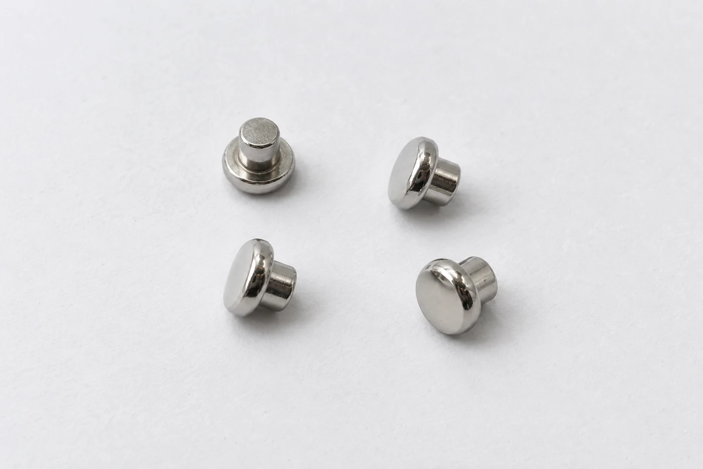
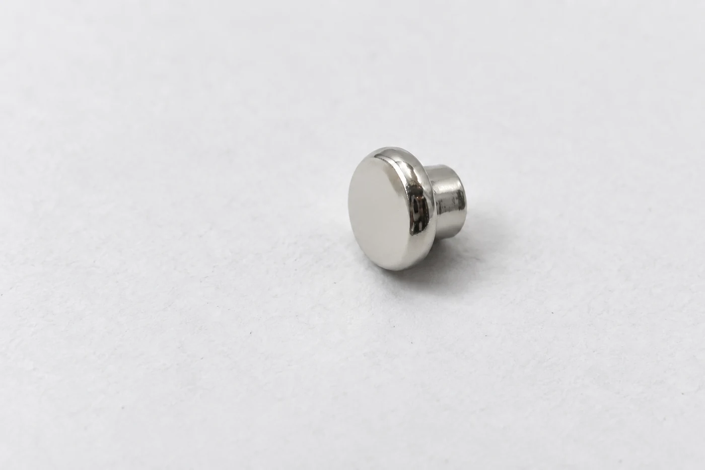
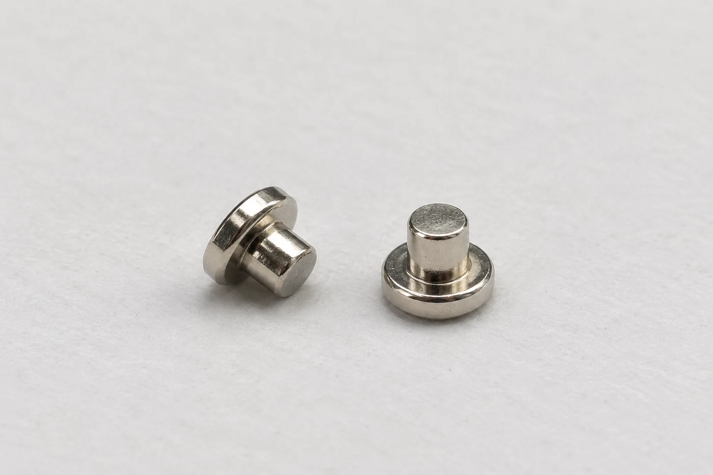
리벳형 접점의 머리부는 상대 접점과 만나는 기능면이고, 몸통과 접합부는 이를 지지하며 전류를 전달합니다. 머리부 외경만 키워도 실제 전도 면적이 비례해 커지는 것은 아닙니다. 접촉 위치, 곡률, 정렬과 지지부의 탄성이 조립된 상태에서 함께 작용합니다.
접촉 구조와 표면층의 내구성
일체형 접점은 기능부가 연속된 접점 재료로 이루어진 구조입니다. 클래드·바이메탈 접점은 작동면의 재료층과 이를 받치는 재료를 접합하고, 전기도금 접점은 모재 표면에 금속막을 형성합니다. 재료 사용량뿐 아니라 마모 후 드러나는 층과 접합 상태가 다르므로, 같은 금색 외관만으로 동일한 구조라고 판단하지 않습니다.
금도금에서는 금층의 기공이나 마모 관통으로 하부 금속이 노출될 수 있습니다. 니켈 하지는 모재 성분의 확산을 억제하고 금층을 기계적으로 지지하는 역할을 할 수 있습니다. 최외층 두께만 지정하기보다 각 층의 조성·연속성·적용 영역과 실제 접촉 위치를 함께 정해야 합니다.
| 설계 항목 | 초기에 확인할 내용 | 수명 후 확인할 내용 |
|---|---|---|
| 접점 형상·정렬 | 만나는 위치·편심·접촉 흔적 | 위치 이동·국부 마모 |
| 힘·오버트래블 | 작동 범위의 힘과 변위 | 접촉력 유지·이탈 여유 |
| 금층·하지·모재 | 층 구성·연속성·기능면 범위 | 마모 관통·노출·부식 |
| 리벳과 지지부의 결합 | 위치·기울기·조립부 전류 경로 | 움직임·접합부 저항 변화 |
표면층 수명은 접촉력, 상대 형상과 미끄럼 거리에도 좌우됩니다. 특정 시험편에서 얻은 도금 두께별 마모횟수를 다른 스위치의 보증수명으로 옮겨서는 안 됩니다. 시제품은 실제 조립 구조로 반복 동작시킨 뒤, 저항 변화와 마모 위치를 함께 대조해 설계의 여유를 확인합니다.
04접촉 기구와 개폐 조건
접촉력·와이핑·기계적 안정성
접촉력은 실제 접촉점의 형성과 유지에 영향을 줍니다. 그러나 힘을 크게 하는 것만으로 신뢰성이 높아지지는 않습니다. 접점 형상, 스프링 변위, 구동 여유와 마모가 함께 바뀌기 때문입니다. 설계에서는 처음 닫힐 때의 힘뿐 아니라 공차와 사용 이력에 따른 최저 접촉력도 검토합니다.
와이핑은 두 기능면이 접촉한 상태에서 상대적으로 미끄러지는 움직임입니다. 얇은 표면막과 입자를 밀어내는 데 도움이 될 수 있지만 마찰과 마모도 발생합니다. 효과는 접점 곡률, 힘, 재료 조합과 이동 경로에 따라 달라지므로 와이핑 거리를 일률적으로 크게 정하지 않습니다.
초기와 수명 말기의 접촉 조건
접점이 닿은 뒤에도 구동부가 움직이는 오버트래블은 접촉을 유지하는 변위 여유와 연결됩니다. 이 여유가 부족하면 마모나 조립 편차로 접촉력이 빠르게 줄 수 있습니다. 반대로 과도한 변위는 스프링 응력과 구동 부담을 높일 수 있으므로 승인된 작동 범위에서 힘과 변위를 함께 확인합니다.
| 설계 요소 | 기대 효과 | 함께 검증할 항목 |
|---|---|---|
| 접촉력 | 실제 접촉점 유지 | 최소 힘·구동 여유·마모 |
| 와이핑 | 표면막·입자 이동 | 기능층 소모·마모분·종료 위치 |
| 오버트래블 | 공차와 마모에 대한 변위 여유 | 스프링 응력·힘의 변화 |
| 다점 접촉 | 분리된 접촉 기회 확보 | 각 지점의 힘·공통 오염·정렬 |
트윈 접점이나 분기형 접점은 미소 부하용 부품에서 활용되는 구조입니다. 다만 접촉 지점이 늘어났다는 이유로 불량 확률이 자동으로 특정 비율만큼 줄어든다고 계산할 수는 없습니다. 두 지점이 같은 오염에 노출되거나 한쪽에 힘이 집중될 수 있으므로 완성된 기구에서 동작과 전기적 안정성을 검증합니다.
최소 적용 부하와 실제 개폐 조건
카탈로그의 최소 적용 부하는 해당 부품을 미소 부하에서 사용할 때 참고하는 조건입니다. Panasonic의 공식 설명도 이를 보증값이 아닌 하한의 안내값으로 구분합니다. 신뢰성은 개폐 빈도, 주변 환경, 허용 접촉저항과 요구 수준에 따라 달라지므로 전압·전류 한 쌍만 보고 사용 가능 여부를 확정하지 않습니다.
최대 개폐 정격, 닫힌 상태의 통전 전류, 최소 적용 부하는 서로 다른 항목입니다. 큰 전류를 흘릴 수 있는 접점이라도 작은 신호를 안정적으로 개폐한다는 뜻은 아닙니다. 반대로 신호용 부품의 미소 부하 성능을 확인했다고 해서 돌입 전류나 유도성 부하까지 허용되는 것도 아닙니다.
개폐 순간의 부하와 통전 조건
접점을 닫은 뒤 전원을 공급하는 동작과 전원이 인가된 회로를 직접 개폐하는 동작은 다릅니다. 센서나 입력 회로에서도 커패시터 충전, 배선의 저장 에너지와 보호 회로 때문에 순간 부하가 달라질 수 있습니다. 정격 검토에는 정상 상태 값과 함께 개폐 순간의 전압·전류 파형을 포함합니다.
| 확인 조건 | 기록할 내용 | 선정상의 의미 |
|---|---|---|
| 실제 신호 범위 | 최소·최대 전압과 전류 | 저수준 신호 안정성과 정격 검토 |
| 개폐 방식 | 통전 중 개폐·무통전 전환·극성 | 표면 변화와 전기적 수명 |
| 순간 부하 | 돌입·차단 파형과 보호 회로 | 정상 전류로 보이지 않는 스트레스 |
| 사용 이력 | 대기 시간·작동 빈도·이전 부하 | 첫 동작과 누적 사용 후의 안정성 |
실기 검증에서는 장기 대기 후 첫 동작과 반복 개폐 후 상태를 구분합니다. 시험 중 여러 번 재동작해 정상으로 돌아왔다면 최초 불량 기록도 보존합니다. 전력 부하를 개폐한 접점을 정밀 신호용으로 전환할 때에는 이전 사용으로 기능면이 달라졌을 가능성까지 포함해 적합성을 다시 확인합니다.
05회로의 검출 여유와 오차
디지털 입력의 검출 여유
디지털 입력은 접점이 물리적으로 닫혔다는 사실만으로 정상 신호를 보장하지 않습니다. 접점과 배선의 저항 때문에 입력 전압이 올라가면 제어기가 닫힘을 인식하지 못하거나 불확정 영역에 머물 수 있습니다. 따라서 접점저항의 허용값은 풀업 저항, 전원 편차, 입력 누설전류와 데이터시트의 입력 문턱을 함께 계산해 정합니다.
풀업 회로로 보는 저항과 입력 전압
설명용으로 3.3V 전원과 10kΩ 풀업 저항을 사용하고, 접점이 입력을 접지에 연결한다고 가정합니다. 누설전류·배선저항·저항 공차는 일단 무시합니다. 이때 입력 전압은 전원전압에 접점저항을 곱한 뒤, 풀업저항과 접점저항의 합으로 나눈 값입니다. 아래 수치는 특정 제품의 측정 결과가 아닌 분압 계산 예입니다.
| 가정한 접점저항 | 입력 전압 | 저수준 최대값을 0.8V로 가정할 때 |
|---|---|---|
| 10Ω | 약 3.30mV | 저수준 범위 안에 있습니다. |
| 1kΩ | 0.30V | 계산상 여유가 있지만 다른 오차도 더해야 합니다. |
| 3.2kΩ | 0.80V | 문턱과 같아 추가 여유가 없습니다. |
| 10kΩ | 1.65V | 저수준을 보장하지 못합니다. |
0.8V는 이 예제에서 정한 값이며 모든 마이크로컨트롤러나 PLC의 기준이 아닙니다. 실제 설계에서는 최악 조건의 전원과 저항 공차, 온도별 누설전류, 접지 전위차를 반영합니다. 순간 저항 상승이 어느 정도 지속돼야 입력으로 인식되는지도 샘플링 주기와 입력 필터를 포함해 확인합니다.
풀업 저항을 줄이면 같은 접점저항에서 입력 전압을 낮출 수 있지만 소비전류와 접점에 가해지는 전기적 조건도 바뀝니다. 슈미트 입력의 히스테리시스와 디바운싱은 잡음·바운스 대응 수단입니다. 지속적인 고저항이나 접촉 단절을 고치는 기능은 아니므로, 회로 보완과 접점 개선의 효과를 따로 검증합니다.
아날로그 신호와 열기전력
아날로그 회로에서는 같은 접점저항도 신호를 전달하는 방식에 따라 다른 오차를 만듭니다. 정해진 전류가 접점을 통과한다면 전압 오차는 전류와 저항의 곱으로 계산할 수 있습니다. 반면 고입력 임피던스의 전압 측정에서는 센서의 정격전류가 아니라 실제 접점을 흐르는 입력 바이어스·누설전류와 회로 구성을 살펴야 합니다.
저항에 의한 오차와 접합부 전압의 구별
예를 들어 100µA가 흐르는 경로의 접점저항이 일시적으로 100Ω이 되면 10mV의 전압강하가 생깁니다. 이는 원리를 보여주는 가정이며 실제 제품의 불량 기준이 아닙니다. 저항이 일정하지 않으면 단순한 영점 보정으로 해결되지 않으며, 신호 변화와 접점 변동을 구별할 시간 기록이 필요합니다.
| 오차 경로 | 관찰할 항목 | 확인 방향 |
|---|---|---|
| 직렬 접점저항 | 실제 경로 전류·저항 변화 | 전압강하와 허용 오차 비교 |
| 열기전력 | 이종금속 접합·온도차·열 안정 시간 | 전류반전 또는 영전류 오프셋 평가 |
| 절연부 누설 | 습도·잔류물·입력 임피던스 | 접촉저항과 절연저항을 별도 측정 |
| 동적 접촉 변동 | 전압 파형·진동·작동 시점 | 정적 평균과 시간영역 기록 비교 |
계측 리드의 이종금속 접합과 온도차가 만드는 열기전력은 미소전압 신호에 더해집니다. 설명용으로 10mΩ에 10mA를 흘리면 저항 신호는 100µV입니다. 일정한 5µV 오프셋이 있으면 정전류 판독은 105µV, 역전류 판독은 −95µV가 됩니다. 두 전압의 차를 전류차 20mA로 나누면 10mΩ를 얻습니다.
전류반전은 두 판독 사이 접점 상태와 열기전력이 충분히 일정할 때 유효합니다. 케이블 이동, 온도 변화, 비선형 표면막이나 소스 제한이 개입하면 오차가 남습니다. 릴레이 코일의 발열과 주변 열원도 기록하고, 반전·안정화 시간과 실제 인가전류를 고정해 결과를 비교합니다.
06저수준 측정과 간헐 불량
저수준 접촉저항과 4선 측정
저수준 접촉저항인 LLCR은 표면막과 미세 접촉부를 시험 전류로 변화시키지 않도록 자극을 제한해 측정합니다. 두 선으로 전류와 전압을 함께 측정하면 리드·연결부의 저항이 섞입니다. 4선식은 전류를 보내는 force 두 선과 전압을 읽는 sense 두 선을 나눠 이 영향을 줄입니다.
전기적 제한과 측정 위치를 함께 지정
IEC 60512-2-1의 공개 시험 조항은 전압 20mV 이하와 전류 100mA 이하를 함께 제시합니다. 직류와 교류의 정의도 구분하며, 교류 전압은 피크값입니다. 이는 저항 합격값이나 최소 사용전류가 아닙니다. 고저항 접점에 100mA를 강제로 흘려 전압 상한을 넘겨서는 안 되며, 전압 제한 상태에서는 실제 전류를 확인해야 합니다.
| 시험계획 항목 | 명확히 정할 내용 |
|---|---|
| 측정 경계 | 접점 계면·스프링·압착부·배선 중 포함되는 구간 |
| 전압 검출 위치 | 양측 sense 접속점과 배선저항 보정 여부 |
| 전기적 자극 | 개방전압·전류 상한·과도현상·실제 전류 |
| 기계적 조건 | 닫힘 위치·지지 방식·외부 힘에 의한 접촉력 변화 |
| 판정 기준 | 초기 절대값·시험 후 절대값 또는 초기 대비 변화량 |
4선을 연결해도 sense 점 안쪽의 단자·스프링 저항은 포함됩니다. 리벳 접점의 계면을 비교할 때와 완성 릴레이의 단자 사이를 검사할 때는 측정 경계가 다릅니다. 프로브가 가동편을 눌러 접촉력을 높이지 않도록 지지하고, 측정 중 접점을 작동시키거나 케이블을 움직이지 않습니다.
도통 부저가 울린다는 것은 장비가 정한 문턱 아래로 저항을 인식했다는 뜻에 가깝습니다. LLCR 합격이나 미소신호 수명 검증을 대신하지 않습니다. 장비의 일반 4선 저항 모드에 드라이 회로 제한이 있는지도 별도로 확인하고, 한 번의 최저값보다 개별 접점의 반복값과 변화를 보존합니다.
간헐 불량 포착과 시험 순서
현장에서만 간헐적으로 끊기던 접점이 검사대에서 정상으로 나오는 이유는 재체결이나 반복 작동으로 계면 상태가 바뀌었기 때문일 수 있습니다. 입고 상태, 마지막 동작과 부하, 체결 방향을 먼저 기록합니다. 세척·연마·고전류 시험을 초기 진단보다 앞세우면 원인에 대한 단서를 잃을 수 있습니다.
정지 상태 저항과 시간영역 관측의 조합
안정된 저항 판독 한 번으로 짧은 개방이나 저항 급증이 없었다고 판단할 수 없습니다. 계측기의 적분·평균 처리, 채널 전환과 기록 공백에 따라 사건이 누락될 수 있습니다. 실제 입력 회로가 반응하는 지속시간을 기준으로 검출 문턱과 시간 분해능을 정하고, 알려진 시험 신호로 기록계의 검출 능력을 확인합니다.
| 관측 단계 | 기록할 내용 | 목적 |
|---|---|---|
| 상태 보존 | 외관·체결·취급·부하 이력 | 초기 계면 상태 확보 |
| 초기 LLCR | 자극 조건·개별 저항·측정 시각 | 저에너지 기준값 설정 |
| 동작·진동 관측 | 문턱·지속시간·파형·작동 신호 | 간헐 사건과 유발 조건 연결 |
| 통제된 재체결·세척 | 처리 전후 값·처리 이력 | 표면·기계적 기여 분리 |
| 재검증 | 동일 조건에서의 재발 여부 | 일시 회복과 지속 개선 구별 |
순간단절 시험은 문턱 저항이나 전압, 최소 지속시간, 대역폭, 동시 감시 채널 수와 검출 공백을 함께 정의해야 재현할 수 있습니다. 예를 들어 1µs를 관찰한다고 정했다면 그 숫자만으로 충분하지 않습니다. 시험기와 배선이 해당 펄스를 왜곡하지 않는지, 여러 채널을 순서대로 읽으며 놓치는 시간이 없는지까지 확인합니다.
이 순서는 고장분석을 위한 구성 예이며 특정 표준의 절차를 그대로 옮긴 것이 아닙니다. 재체결로 저항이 낮아져도 원인이 오염인지 마모 분말인지 위치 변화인지 아직 구분되지 않습니다. 처리하지 않은 비교 시료를 남기고, 저항·파형·표면 관찰을 함께 해석합니다.
07환경 검증과 원인 분석
환경·동작 수명 검증
미소전류 접점의 수명시험은 반복 개폐 횟수만 세는 작업이 아닙니다. 통전하는 동안 안정적인 접점도 장기간 비작동 상태로 놓인 뒤 첫 작동에서 다른 거동을 보일 수 있습니다. 사용 온습도, 오염원, 보관 시간, 작동 빈도와 부하 파형을 시험계획에 연결해야 장비의 실제 사용 조건을 평가할 수 있습니다.
환경·기계·전기 조건의 시험 순서
리벳 접점과 스위치는 개폐 중 표면 변화와 접촉력 유지가 중요하고, 분리형 커넥터는 체결 마모와 체결 후 미세 움직임도 따져야 합니다. 서로 다른 구조를 같은 수명 숫자로 비교하지 않습니다. 시험 전·중간·후의 저항뿐 아니라 동작 중 순간단절과 시험 후 마모 위치를 함께 기록합니다.
| 검증 조건 | 시험에 반영할 변수 | 주요 판독 |
|---|---|---|
| 장기 비작동 | 온습도·대기·유지 시간·첫 개폐 | 첫 작동 저항·이후 회복 여부 |
| 반복 개폐 | 전압·전류·개폐 속도·휴지 시간 | 저항 분포·바운스·표면 손상 |
| 열적 조건 | 온도 범위·체류 시간·실제 발열 | 접촉력·저항·기구 변위 |
| 기계적 조건 | 고정·진동·충격·배선 하중 | 순간단절·풀림·위치 변화 |
| 표면 환경 | 습기·부식성 기체·공정 잔류물 | 막·부식·도금 손상·저항 변화 |
환경 강도를 높이면 항상 더 좋은 시험이 되는 것은 아닙니다. 실제와 다른 반응이나 재료 손상을 유발하면 사용 수명으로 환산하기 어렵습니다. 마모 후 대기 노출처럼 연속 시험이 필요한 경우와 각 원인을 분리하는 시험군을 나눌 경우를 구분하고, 조건과 순서를 승인된 계획으로 고정합니다.
합격기준에는 초기 절대저항, 시험 후 저항 또는 변화량, 기능상 허용되는 순간단절을 명시합니다. 모든 시료가 정상이어도 시험하지 않은 환경과 기간까지 무고장을 보증하지는 않습니다. 시험 시료 수·로트·총 동작·관측 시간과 검출 한계를 함께 보고해야 결과의 범위를 판단할 수 있습니다.
증상별 원인 분리와 개선
접촉불량을 발견하면 먼저 계측 경로와 접점 자체를 구분합니다. 시험 리드와 지그의 접속 불량, 전류원의 전압 제한, 코일 구동 부족도 접점 문제처럼 보일 수 있습니다. 외관이 깨끗하다는 이유로 표면막을 배제하거나 저항이 높다는 이유로 재료만 바꾸면 실제 원인을 놓치기 쉽습니다.
증상에서 확인 항목과 변경 변수로 연결
| 관찰한 증상 | 우선 분리할 원인 | 확인·개선 방향 |
|---|---|---|
| 첫 작동 불량, 반복 후 회복 | 표면막·입자·접촉 위치 변화 | 초기 상태 보존 후 표면·와이핑 검토 |
| 진동 중 짧은 단절 | 접촉력 저하·기구 유격·배선 하중 | 파형과 변위 비교, 지지·형상 재검토 |
| 수명 후 저항 상승 | 도금 마모·분말·스프링 변화 | 마모 위치와 힘-변위 곡선 비교 |
| 전류에 따라 판독 변화 | 표면막 비선형·가열·소스 제한 | 실제 자극 확인 후 원인별 시험 분리 |
| 온도에 따라 미소전압 편이 | 열기전력·벌크저항·기구 변형 | 반전 측정과 열 안정·접촉력 확인 |
표면 문제는 재료·도금만으로 해결되지 않을 수 있습니다. 세척 잔류물, 포장재와 공정 분위기, 조립 중 접촉부 취급을 함께 확인합니다. 마모가 원인이면 접촉력이나 와이핑을 늘리는 조치가 오히려 수명을 줄일 수 있으므로, 이동 경로·표면 조합과 마찰을 함께 바꿔 비교합니다.
기계적 문제는 완성 조립 상태에서 평가합니다. 접점 리벳의 체결 변형, 가동편의 평행도, 스프링의 유효 길이와 정지 위치가 달라지면 같은 접점 재료라도 힘과 접촉 위치가 바뀝니다. 코일 구동전압이나 액추에이터 변위가 부족한 상태를 접점 표면의 불량으로 분류하지 않도록 구동 신호도 동시에 확인합니다.
개선안은 한 번에 바꾸는 변수를 줄여 원인과 효과를 확인하고, 최종 사양에서는 실제 조합으로 재시험합니다. 처리하지 않은 비교군과 변경 이력을 남기면 세척 후 일시 회복, 힘 증가에 따른 초기 개선, 수명 후 재발을 구분할 수 있습니다. 마지막 판정은 저항 수치와 장비의 실제 신호 검출을 함께 만족하는지로 내려야 합니다.
08제조 품질과 발주 기준
리벳 성형·접합·표면 품질 관리
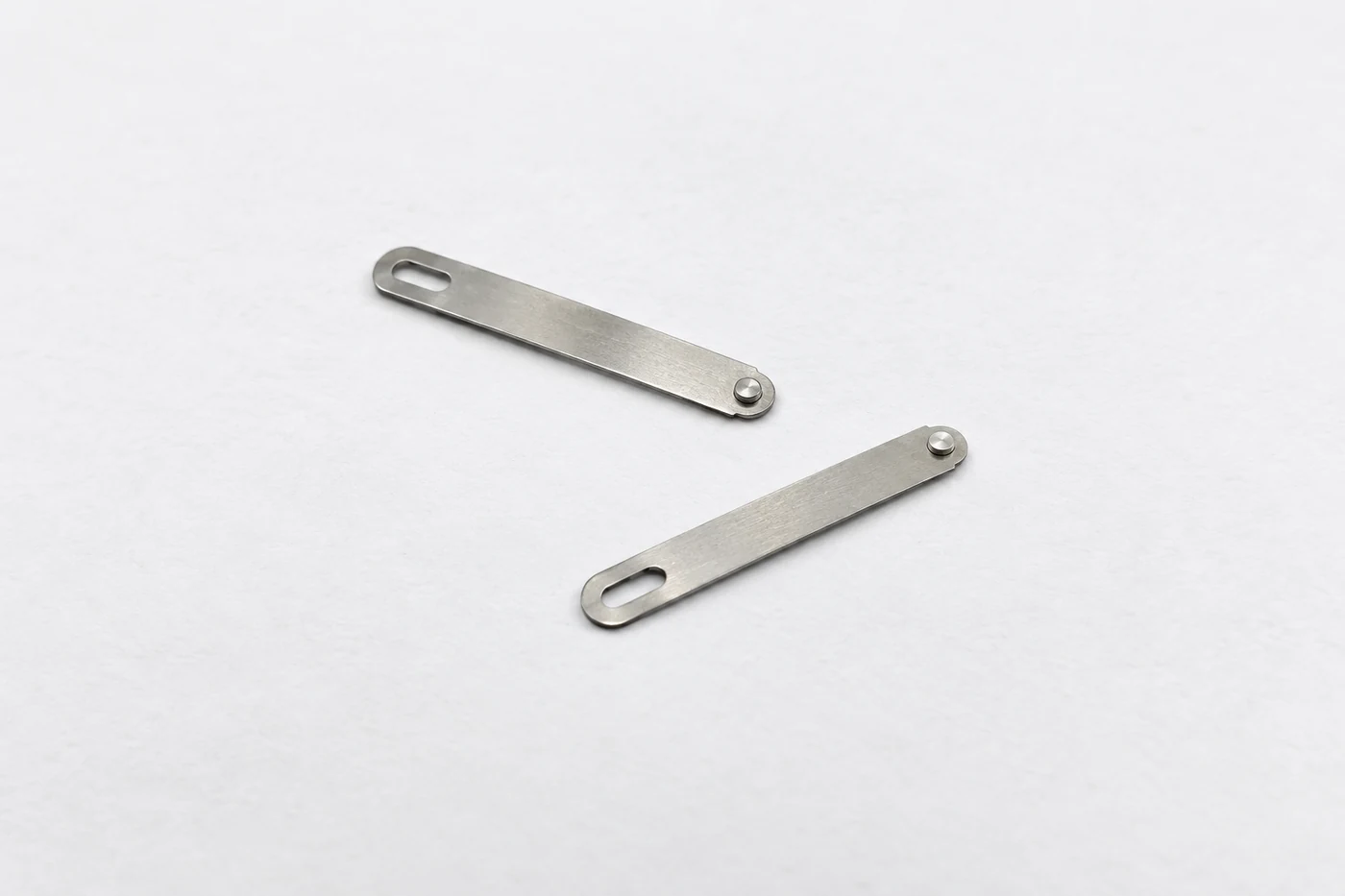
리벳형 전기접점의 품질은 기능면, 몸체의 형상, 접촉 재료의 결합부와 장착부를 나누어 관리해야 합니다. 리벳을 접촉암에 고정하는 기계적 체결과 클라드 재료층의 금속학적 결합은 서로 다른 계면입니다. 어느 위치에서 저항이나 강도 문제가 발생했는지 구분할 수 있도록 도면과 검사 기준을 연결합니다.
성형 상태에서는 머리와 섕크의 정렬, 기능면 형상, 가장자리 손상과 균열을 확인합니다. 장착 후에는 흔들림이나 기울어짐, 지지부 변형과 접촉 위치를 다시 확인합니다. 외형 치수가 합격하더라도 조립으로 접촉력과 닫힘 위치가 바뀔 수 있으므로 단품 검사와 조립 기능 검사를 구분합니다.
외관·층 두께·전기적 기능의 구분
표면처리가 지정된 접점은 층의 재질, 위치와 두께 조건을 관리합니다. XRF는 적절한 측정 모델과 교정 조건에서 층 두께와 조성 확인에 활용할 수 있습니다. 그러나 그 결과만으로 미세공, 접착 상태나 미소전류 성능까지 합격이라고 판단하지 않습니다. 필요한 특성마다 적합한 검사와 전기 시험을 연결합니다.
| 관리 대상 | 주요 확인 항목 | 남길 기록 |
|---|---|---|
| 소재·재료 구조 | 승인 재질·층 구성·변경 여부 | 소재 식별·로트·승인 이력 |
| 성형·장착부 | 정렬·손상·고정 상태 | 치수·외관·필요한 접합 검사 |
| 기능면·표면처리 | 표면 상태·지정 층·청정도 | 검사 위치·방법·조건 |
| 완성 접점계 | 접촉력·작동·전기적 안정성 | 시험 조건·전후 변화·불량 이력 |
세척 이후의 취급과 포장도 관리 범위에 포함합니다. 기능면에 손이 닿거나 포장재의 먼지·잔류물이 옮겨가면 앞선 세척 효과가 유지되지 않을 수 있습니다. 재질, 표면처리 또는 세척 공정을 변경할 때에는 로트를 구분하고, 영향을 받는 특성의 재검증 범위를 정해 동일한 납품 품질 기준에 연결합니다.
도면·발주 사양과 합격 기준
미소전류 접점의 발주 사양은 형상과 재질에 실제 사용 조건을 더해야 완성됩니다. 접점이 전달할 신호 범위, 회로 임계값 또는 허용 오차, 개폐 방식과 환경을 함께 전달합니다. 재료가 아직 정해지지 않았다면 이름만 임의로 지정하기보다 해결해야 할 기능과 검증 조건부터 명확히 합니다.
도면에는 기능면과 장착 기준, 상대 접점의 형상, 요구 재료층과 표면처리 범위를 구분합니다. 접촉력과 작동 변위가 별도 기구에서 결정된다면 그 조건도 함께 관리해야 합니다. 접점 단품의 치수만으로 완성된 센서나 스위치의 신호 신뢰성을 보증하는 방식은 적절하지 않습니다.
합격 수치와 측정·사용 조건
접촉저항 허용값에는 시험 전류, 전압 제한, 측정 위치와 측정 시점을 함께 적습니다. 순간 단선은 판정 임계값과 지속시간, 기록 장비의 시간 분해능까지 정해야 비교할 수 있습니다. 초기 상태, 환경 노출 후와 수명 시험 후를 나누고 필요한 시료 수와 불합격 처리 기준을 시험 전에 합의합니다.
| 발주 입력 | 명확히 할 내용 | 연결되는 판단 |
|---|---|---|
| 회로와 부하 | 신호 범위·임계값·개폐 파형 | 재료·표면과 실제 기능 검증 |
| 기구와 도면 | 기능면·기준·상대 형상·힘·변위 | 가공·성형·조립 조건 |
| 환경과 수명 | 온습도·오염·대기·작동 이력 | 검증 순서와 시험 범위 |
| 검사와 추적성 | 시험 조건·합격 기준·로트 기록 | 인수 판정과 재제작 일관성 |
견적은 접점의 재료비뿐 아니라 성형·접합·표면처리, 검사와 검증 범위를 같은 조건으로 비교합니다. 개발 단계에서는 사용 회로와 도면을 먼저 정리하고, 시제품에서 확인할 항목을 선정하면 변경 원인을 추적하기 쉽습니다. 필요한 신호 성능과 검사 조건이 정리될수록 제작 상담도 구체적으로 진행할 수 있습니다.
English Edition · Low-Level Signal Contacts
Low-level signal contacts are not necessarily easy to design simply because they carry little current. Even when a contact is mechanically closed, surface films or momentary contact instability can interrupt a sensor signal or cause an incorrect input-state decision.
Stable signal transmission requires contact material, contact force, actual switching load, circuit detection margin and measurement conditions to work together. Electrical-contact principles and circuit examples connect material, structure, manufacturing quality, low-level resistance measurement and life validation into a coherent decision process.
Small current, different failure mechanisms
Check how surface films and brief interruptions affect signal detection.
Material and contact structure together
Material, finish, contact force and switching conditions matter more than a gold-colored appearance.
Testing that preserves failure evidence
Distinguish low-level testing from actual-circuit validation and control their sequence.
01Signal failures and load definitions
Signal failures in low-current electrical contacts
Low-current electrical contacts connect small signals between sensors and control circuits. A pressed switch or an audible relay operation does not establish that a stable conducting path exists between the contacts. Diagnosis begins by separating mechanical operation from electrical continuity.
Circuit-specific errors and allowable limits
At low loads, surface films and contamination can obstruct signals even when thermal damage to the contacts is limited. A high current rating describes the ability to handle a large load. That rating alone does not establish continuity at low voltage and current. The contact material and structure must match the actual electrical load.
The consequences of a contact fault depend on the circuit. A digital input can change state when its voltage crosses a decision threshold or the connection is briefly interrupted. In a low-level analog circuit, changes in signal-path resistance and noise can disturb the reading. Instead of accepting every contact against one resistance value, first define the operating margin and allowable interruption time of the particular input.
| Observed symptom | Contact-side checks | Circuit-side checks |
|---|---|---|
| Operation without an input-state change | Continuity, surface films and contact force | Input thresholds and pull-up or pull-down |
| Instability only on the first operation after storage | Storage environment and surface contamination | Actual load on the first operation |
| Intermittent signal loss during vibration | Contact separation, fretting and retention | Detection bandwidth and allowable interruption |
| Irregular analog readings | Contact-resistance changes and interface condition | Input architecture, signal magnitude and error budget |
Reliability assessment does not end with the initial resistance of a new contact. It must consider signal continuity on the first operation after storage, after repeated switching, and after temperature changes and vibration. Selection of contact rivets or switching devices should be based on this service history.
Low loads, dry circuits and voltage-free contacts
A low load cannot be defined by small current alone. Open-contact voltage, closed-contact current, the peak at closure and switching frequency all matter. Even a circuit with low steady-state current can impose different electrical stress while its capacitance charges.
Conditions behind similar terminology
In contact reliability, a dry circuit denotes low-energy conditions that do not materially change the contact through heat or discharge. A voltage-free contact, by contrast, describes an output that does not supply its own voltage to the external circuit. Its externally connected source and load can still apply voltage and current.
Dry switching can mean opening and closing contacts without load current flowing. A low-level contact-resistance test limits the test voltage and current to avoid altering the interface. Despite the similar names, application conditions and measurement conditions must be specified separately.
| Term | What it describes | Information to specify |
|---|---|---|
| Low load | The actual circuit load imposed on the contact | Open-circuit voltage, steady current and transient waveform |
| Dry circuit | Low-energy conditions that do not alter the interface | Applicable test method and voltage/current limits |
| Voltage-free contact | How the output supplies power | External supply, isolation and connected load |
| Dry switching | Whether current flows during switching | Sequence of current application and contact operation |
A manufacturer’s minimum applicable load is generally a selection reference established under particular conditions. It should not be treated as a guaranteed lower limit in every environment or transferred directly between products. Low-current electrical contacts require evaluation of switching frequency, atmosphere, inactive periods and the resistance changes the circuit can tolerate.
02Contact resistance and surface condition
Real contact spots and surface-film resistance
Even when a contact head appears broad, current does not flow through its entire visible area. Microscopic roughness causes the two metal surfaces to touch initially at selected asperities. The size and distribution of these real contact spots determine the current paths.
Current constriction and surface-film effects
Constriction resistance develops as current converges into small contact spots and spreads out again. Oxides, sulfides or organic contamination add the influence of a surface film. Consequently, high bulk conductivity does not maintain low contact resistance when the interface through which current must pass is unstable.
Increasing contact force can change the real contact area and the disruption of surface films. At the same force, however, surface curvature, material hardness, coating layers and supporting structure produce different stress distributions. Excessive force also increases insertion or actuation demands and surface wear, so force and displacement must be designed together in the assembled state.
| Contribution to resistance | Governing factors | Design and inspection focus |
|---|---|---|
| Bulk path through the contact and spring | Conductivity, length and cross-section | Geometry and the complete current path |
| Current constriction at the interface | Real contact area, force and geometry | Force at operating positions and contact marks |
| Surface films and particles | Composition, thickness, distribution and disruption | Cleanliness, atmosphere and low-level resistance |
| Assembly and joining interfaces | Fastening or joint condition | Sense-terminal positions and separation of paths |
In the measurement relation R=ΔV/I, ΔV is the voltage drop between the specified sensing points. It is not the supply voltage or the voltage across an open contact. Resistance measured between terminals may include the rivet, spring and joints, so the measurement boundary must first be defined.
Contamination, corrosion and fretting
Contamination affecting low-current electrical contacts is not limited to visible dust. Thin films can restrict conducting paths, while particles can hold contacts apart or change where they touch. Control must cover contamination introduced during storage, assembly and service as well as the condition immediately after cleaning.
Chemical reactions and small relative motion
Silver-based surfaces require attention to sulfide films in sulfur-containing atmospheres. Volatile constituents from nearby adhesives or sealants must also be considered. Deposition of siloxane gases and their conversion into insulating material at contacts have been reported; a plastic seal therefore does not establish protection against every gaseous influence.
Fretting is repeated small relative movement between contacting surfaces. On oxide-forming surfaces such as tin, repeated exposure, oxidation and wear change the interface. Differential thermal expansion between components can cause it as well as vibration. An intentional wipe during engagement must be distinguished from small slips accumulated over service.
| Degradation route | Causes to investigate | Observations to retain |
|---|---|---|
| Dust or particle ingress | Handling, storage, sealing and wear debris | Particle locations and contact marks |
| Chemical surface films | Sulfur gases, organics, humidity and time | Environmental history and surface analysis |
| Fretting | Vibration, thermal deformation and retention | Interface displacement and resistance changes |
| Instability after prolonged inactivity | Surface changes and infrequent switching | Difference between first and later operations |
A study of simulated tin-plated contacts observed resistance rising, falling and increasing again. This illustrates why one normal repeat measurement cannot exclude a fault. Recording the initial resistance and the environmental and operating history before moving or wiping a failed part helps preserve evidence of its cause.
03Materials, construction and surface layers
Choosing gold, silver, palladium-based materials and tin
Contact materials should be selected against the actual load and the environment their surfaces must withstand, rather than a conductivity ranking. The result depends on alloy composition, whether the material forms the bulk contact or a surface layer, and the mating contact. Material guidance for switching rivets and separable connectors must also be applied separately.
Combining alloy and surface finish
Gold-based surfaces are useful candidates for low-level conditions where stable metallic contact is difficult to establish. A thin gold flash, however, does not imply the same service life as a sufficiently thick gold layer or gold cladding. Silver-based contacts can offer high conductivity and useful switching properties, but sulfide formation and surface films require separate evaluation at low loads.
Palladium-based contacts cannot be treated as a single material. Silver-palladium, AgPd, differs from palladium-nickel systems, PdNi, and gold-covered composite surfaces are another distinct construction. Material-specific concerns, such as organic-gas-related polymer formation on AgPd, must be checked without assuming an identical failure mechanism for every palladium-based system.
| Material or surface system | Useful evaluation direction | Key checks |
|---|---|---|
| Gold-based surface | Interface stability for low-level signals | Gold-layer structure, underlayer, pores and wear |
| Silver and silver alloys | Combined conductivity and switching demands | Sulfidizing atmosphere and minimum applicable load |
| Palladium-based systems | Durability and environmental suitability of each alloy or composite | Exact composition, gold surface layer and organic gases |
| Tin-plated connector | Mechanically stable low-level connection | Contact force, wipe, mating finish and fretting |
Tin need not be considered categorically unsuitable for low-current service. The contact structure that penetrates its oxide film and the control of relative motion are important. Arbitrarily mating gold with tin can introduce tin transfer and oxide accumulation, so changing the finish on only one part requires evaluation of the complete contact pair.
Contact construction and surface-layer life
The head of a rivet contact is the functional surface that meets its counterpart; its shank and joint provide support and carry current. Simply enlarging the head diameter does not increase the real conducting area in direct proportion. Contact position, curvature, alignment and support compliance act together in the assembled device.
Contact construction and surface-layer durability
A solid contact has a functional body made from a continuous contact material. Clad or bimetal contacts bond a working material layer to a supporting material, while electroplated contacts form a metallic film on the substrate surface. These constructions differ in material usage, the layers exposed by wear and their interfaces, so the same gold-colored appearance does not establish an identical construction.
In gold-plated contacts, pores or wear-through can expose the underlying metal. A nickel underlayer can inhibit diffusion of base-metal constituents and provide mechanical support for the gold. Rather than specifying only the outer-layer thickness, define each layer’s composition, continuity and coverage together with the actual contact location.
| Design item | Initial checks | Checks after service testing |
|---|---|---|
| Contact geometry and alignment | Meeting position, offset and contact marks | Position shift and localized wear |
| Force and overtravel | Force and displacement through the operating range | Retained force and margin against separation |
| Gold, underlayer and substrate | Layer structure, continuity and functional coverage | Wear-through, exposure and corrosion |
| Connection of rivet and support | Position, tilt and assembly current path | Movement and joint-resistance changes |
Surface-layer life also depends on contact force, mating geometry and sliding distance. Wear-cycle results for particular coating thicknesses on one test specimen must not become a guaranteed life for another switch. Prototype evaluation should therefore combine repeated operation in the actual assembly with comparison of resistance changes and wear locations to assess the design margin.
04Contact mechanics and switching conditions
Contact force, wiping and mechanical stability
Contact force influences the formation and retention of real contact spots. Increasing force alone does not establish higher reliability. Contact geometry, spring deflection, actuation margin and wear interact. Evaluate the minimum force under tolerances and service history, as well as the force at initial closure.
Wiping is relative sliding between two working surfaces while they are in contact. It can help displace light surface films and particles, but it also produces friction and wear. Its effectiveness depends on contact curvature, force, material pairing and the motion path. A larger wiping distance is therefore not a universal design objective.
Initial and end-of-life contact conditions
Overtravel after the contacts first touch is related to the displacement margin that maintains contact. Insufficient margin can allow wear or assembly variation to reduce contact force rapidly. Excessive travel can increase spring stress and actuation demand. Verify force and displacement together throughout the approved operating range.
| Design feature | Intended benefit | Items to verify together |
|---|---|---|
| Contact force | Retention of real contact spots | Minimum force, actuation margin and wear |
| Wiping | Displacement of films and particles | Functional-layer loss, debris and final position |
| Overtravel | Displacement margin for tolerances and wear | Spring stress and force variation |
| Multiple contact points | Separate opportunities for contact | Force at each point, common contamination and alignment |
Twin or bifurcated contacts are used in components intended for low-level loads. Increasing the number of contact points does not automatically reduce failure probability by a calculable fixed ratio. Both points can encounter the same contamination, or force can concentrate on one point. Verify motion and electrical stability in the completed mechanism.
Minimum applicable load and actual switching conditions
A catalog minimum applicable load provides guidance for using that component at low load levels. Panasonic explicitly distinguishes this guidance from a guaranteed lower limit. Reliability depends on switching frequency, environment, acceptable contact resistance and the required performance level. A voltage–current pair alone does not establish suitability.
Maximum switching ratings, current carrying capability while closed, and minimum applicable load describe different conditions. A contact capable of carrying substantial current does not necessarily switch small signals reliably. Verified low-level performance also does not authorize inrush current or inductive loads beyond the component specification.
Switching transients and carrying conditions
Applying power after contact closure differs from directly switching an energized circuit. Even sensor and input circuits can experience transient loads from capacitor charging, stored wiring energy and protective circuits. Rating assessment should include voltage and current waveforms at opening and closing, alongside steady-state values.
| Condition | Information to record | Selection significance |
|---|---|---|
| Actual signal range | Minimum and maximum voltage and current | Low-level stability and rating assessment |
| Switching mode | Energized switching, unenergized transfer and polarity | Surface changes and electrical life |
| Transient load | Make/break waveforms and protective circuitry | Stress hidden by steady-state current |
| Service history | Idle duration, operating frequency and previous loads | Stability on first operation and after accumulated use |
Application testing should distinguish the first operation after prolonged idle time from the condition after repeated switching. Preserve an initial failure even if subsequent operations restore conduction. Before transferring a contact from power switching to precision signals, reassess suitability with the possibility that earlier service changed its working surface.
05Circuit detection margin and error
Detection margin in digital inputs
Physical contact closure alone does not guarantee a valid digital input. Resistance in the contact and wiring can raise the input voltage until the controller no longer recognizes closure or operates in an undefined region. The allowable contact resistance therefore depends on the pull-up resistance, supply variation, input leakage and the input thresholds specified in the device datasheet.
Contact resistance in a pull-up circuit
For illustration, assume a 3.3 V supply, a 10 kΩ pull-up resistor and a contact connecting the input to ground. Initially neglect leakage, wiring resistance and resistor tolerance. The input voltage equals the supply voltage multiplied by the contact resistance, divided by the sum of the pull-up and contact resistances. The following figures are divider calculations, not measurements from a product.
| Assumed contact resistance | Input voltage | With an assumed maximum low-input level of 0.8 V |
|---|---|---|
| 10 Ω | Approximately 3.30 mV | Within the low-input range. |
| 1 kΩ | 0.30 V | A calculated margin remains, but other errors must be included. |
| 3.2 kΩ | 0.80 V | At the threshold, with no additional margin. |
| 10 kΩ | 1.65 V | A valid low input is not guaranteed. |
The 0.8 V threshold is an assumption for this example, not a universal microcontroller or PLC requirement. An actual design includes worst-case supply and resistor tolerances, temperature-dependent leakage and ground-potential differences. Sampling and input filtering also determine how long a resistance excursion must persist before the system recognizes it.
Reducing the pull-up resistance lowers the input voltage for a given contact resistance, but changes current consumption and the electrical conditions at the contact. Schmitt-input hysteresis and debouncing address noise and bounce. They do not repair persistent high resistance or loss of contact, so circuit changes and contact improvements require separate verification.
Analog signals and thermal EMF
The same contact resistance produces different errors in different analog circuits. If a defined current flows through the contact, its voltage drop is the product of current and resistance. In a high-input-impedance voltage measurement, however, the relevant quantities are the bias and leakage currents actually crossing the contact and the circuit topology, rather than the sensor’s rated current.
Separating resistive error from junction voltage
For example, a contact temporarily reaching 100 Ω in a path carrying 100 µA produces a 10 mV drop. These assumed values illustrate the principle and are not a product failure limit. If resistance varies, a fixed zero correction cannot remove the resulting error; a time record is needed to distinguish signal changes from contact fluctuations.
| Error path | What to observe | Evaluation |
|---|---|---|
| Series contact resistance | Actual path current and resistance changes | Compare voltage drop with the error budget |
| Thermal EMF | Dissimilar-metal junctions, temperature gradients and settling time | Evaluate current reversal or zero-current offset |
| Insulation leakage | Humidity, residues and input impedance | Measure contact and insulation resistance separately |
| Dynamic contact variation | Voltage waveform, vibration and actuation timing | Compare static averages with time records |
Thermal EMF from dissimilar-metal lead junctions and temperature gradients adds to the small measured voltage. As an illustration, 10 mA through 10 mΩ produces a resistive signal of 100 µV. With a constant 5 µV offset, the positive-current reading is 105 µV and the negative-current reading is −95 µV. Dividing the voltage difference by the 20 mA current difference gives 10 mΩ.
Current reversal is effective when contact condition and thermal EMF remain sufficiently stable between the two readings. Cable movement, temperature change, nonlinear films or source limiting can leave errors. Record heating from relay coils and nearby sources, and compare results using controlled reversal and settling times and the actual applied current.
06Low-level measurement and intermittent failures
Low-level contact resistance and four-wire measurement
Low-level contact resistance, or LLCR, is measured with a limited stimulus intended to avoid changing surface films and microscopic contact spots. A two-wire measurement includes lead and connection resistance because the same wires carry current and sense voltage. Four-wire measurement separates the two force leads from the two sense leads to reduce this contribution.
Specify both stimulus limits and sensing locations
The publicly available clauses of IEC 60512-2-1 specify both a voltage limit of 20 mV and a current limit of 100 mA. DC and AC quantities are distinguished, with AC voltage expressed as peak value. These are neither resistance acceptance limits nor minimum service current. Forcing 100 mA through a high-resistance contact must not violate the voltage limit; actual current must be checked when the source reaches voltage compliance.
| Test-plan item | Required definition |
|---|---|
| Measurement boundary | Included interface, spring, crimp and wire sections |
| Voltage-sensing locations | Sense nodes on both sides and any wire-resistance correction |
| Electrical stimulus | Open-circuit voltage, current ceiling, transients and actual current |
| Mechanical condition | Closed position, support and externally induced contact-force changes |
| Acceptance criteria | Initial absolute value, final absolute value or change from baseline |
Even with four wires, resistance in terminals and springs inside the sense nodes remains included. Comparing a riveted contact interface and testing a complete relay between its terminals therefore use different boundaries. Support the assembly so probes do not press the moving member and increase contact force, and avoid actuation or cable movement during the measurement.
A continuity beep primarily indicates that the instrument detected a resistance below its configured threshold. It does not establish an LLCR pass or low-level signal life. Separately confirm whether the instrument’s ordinary four-wire resistance mode provides dry-circuit limits, and retain repeated readings and changes for individual contacts rather than reporting only the lowest value.
Capturing intermittent faults and preserving test order
A contact that fails intermittently in service may appear normal on the bench because remating or repeated operation changed its interface. First record the received condition, last operation and load, and mating orientation. Cleaning, polishing or high-current testing before the initial diagnosis can remove evidence of the cause.
Combine stationary resistance with time-domain observation
A single stable resistance reading cannot establish the absence of brief opens or resistance spikes. Integration, averaging, channel switching and recording gaps can hide events. Define the detection threshold and time resolution from the duration to which the actual input circuit responds, and verify the recorder’s detection capability using a known test signal.
| Observation stage | Record | Purpose |
|---|---|---|
| Preserve received condition | Appearance, mating, handling and load history | Retain evidence of the original interface |
| Initial LLCR | Stimulus, individual resistance and timestamp | Establish a low-energy baseline |
| Operation and vibration | Threshold, duration, waveform and actuation signal | Link events with provoking conditions |
| Controlled remating or cleaning | Before/after readings and treatment history | Separate surface and mechanical contributions |
| Reverification | Recurrence under the same conditions | Distinguish temporary recovery from sustained improvement |
A reproducible discontinuity test defines resistance or voltage threshold, minimum duration, bandwidth, simultaneously monitored channels and detection gaps together. Choosing to observe 1 µs events, for example, is insufficient by itself. Verify that the instrument and wiring do not distort those pulses and that sequential channel readings do not leave unobserved intervals.
This sequence is a proposed diagnostic structure, not a reproduction of a particular standard procedure. A resistance decrease after remating does not yet distinguish contamination, wear debris or positional change. Retain untreated comparison specimens and interpret resistance, waveforms and surface observations together.
07Environmental validation and diagnosis
Environmental and operating-life verification
Life testing of low-current contacts involves more than counting operations. A contact that remains stable during conduction may behave differently on its first operation after a long inactive period. Link the plan to service temperature and humidity, contamination sources, storage time, operating frequency and load waveforms to evaluate actual equipment use.
Sequence of environmental, mechanical and electrical conditions
For riveted contacts and switches, surface changes during operation and retention of contact force are central concerns. Separable connectors also require evaluation of mating wear and small movements after mating. Different structures should not be compared using an undifferentiated life count. Record resistance before, during and after testing, interruptions during operation and the locations of wear afterward.
| Verification condition | Variables in the test | Main observations |
|---|---|---|
| Long inactivity | Temperature, humidity, atmosphere, dwell and first operation | First-operation resistance and subsequent recovery |
| Repeated operation | Voltage, current, operating speed and dwell | Resistance distribution, bounce and surface damage |
| Thermal conditions | Temperature range, dwell and actual heat generation | Contact force, resistance and displacement |
| Mechanical conditions | Mounting, vibration, shock and wiring loads | Interruptions, loosening and positional change |
| Surface environment | Moisture, corrosive gases and process residues | Films, corrosion, plating damage and resistance changes |
Increasing environmental severity does not automatically improve a test. If it produces reactions or material damage unlike those in service, translating the result into service life becomes difficult. Distinguish sequential exposure, such as atmosphere after wear, from separate groups used to isolate causes, and fix conditions and sequence in an approved plan.
Acceptance criteria specify initial absolute resistance, final resistance or its change, and functionally acceptable interruptions. Passing all specimens does not guarantee failure-free behavior in untested environments or periods. Report specimen count, lots, total operations, observation time and detection limits so the scope of the evidence can be assessed.
Separating causes and selecting corrective actions
When a contact fault appears, first distinguish the measurement path from the contact itself. Faulty leads or fixture connections, source voltage compliance and insufficient coil drive can resemble a contact defect. Dismissing films because a surface looks clean, or replacing the material solely because resistance is high, can miss the underlying cause.
Link symptoms to checks and controlled changes
| Observed symptom | Causes to separate first | Checks and improvement direction |
|---|---|---|
| First-operation failure followed by recovery | Films, particles or changed contact location | Preserve baseline, then examine surface and wipe |
| Brief interruptions during vibration | Reduced force, mechanical play or wiring load | Compare waveforms and displacement; review support and geometry |
| Resistance rise after life testing | Plating wear, debris or spring changes | Compare wear locations and force-displacement curves |
| Reading changes with current | Nonlinear films, heating or source compliance | Verify actual stimulus and separate causal tests |
| Temperature-dependent voltage shift | Thermal EMF, bulk resistance or mechanical deformation | Check reversal readings, thermal settling and contact force |
Material or plating changes alone may not solve a surface problem. Check cleaning residues, packaging materials, process atmosphere and handling of the contact area during assembly. If wear is responsible, increasing force or wipe can instead shorten life; compare controlled changes in travel path, mating surfaces and friction together.
Evaluate mechanical problems in the completed assembly. Deformation from setting a contact rivet, moving-member alignment, effective spring length and stop position can change force and contact location even with identical contact material. Monitor the drive signal as well, so insufficient coil voltage or actuator travel is not misclassified as a defective contact surface.
Limit the number of variables changed at once to identify causes and effects, then retest the final specification as an actual combined assembly. Untreated controls and change records help distinguish temporary recovery after cleaning, initial improvement from higher force and later recurrence. Final acceptance requires both the resistance criteria and reliable signal detection in the equipment.
08Manufacturing quality and procurement criteria
Rivet forming, attachment and surface quality control
Quality control for a contact rivet should distinguish its working face, body geometry, contact-material bond and attachment to the carrier. Mechanical riveting to a contact arm and the metallurgical bond of a clad layer are different interfaces. Link drawings and inspection criteria so that electrical or mechanical problems can be assigned to the correct location.
Check head-to-shank alignment, working-face geometry, edge damage and cracking after forming. After attachment, reassess looseness, tilt, carrier deformation and contact position. Assembly can change contact force and closure position even when individual dimensions pass. Separate component inspection from functional inspection of the assembly.
Distinguishing appearance, layer thickness and electrical function
For contacts with a specified finish, control layer material, location and thickness requirements. XRF can support thickness and composition measurements with an appropriate measurement model and calibration. Its result alone does not establish acceptable porosity, adhesion or low-level electrical performance. Assign a suitable inspection or electrical test to each required characteristic.
| Control target | Main checks | Records to retain |
|---|---|---|
| Material and architecture | Approved composition, layer system and changes | Material identity, lot and approval history |
| Formed part and attachment | Alignment, damage and retention | Dimensions, appearance and required joint inspection |
| Working face and finish | Surface condition, specified layers and cleanliness | Inspection locations, methods and conditions |
| Complete contact system | Force, operation and electrical stability | Test conditions, before/after changes and failures |
Control handling and packaging after cleaning as well. Touching a working face or transferring dust and residues from packaging can compromise the earlier cleaning result. Distinguish lots when material, finishing or cleaning processes change. Define revalidation for the affected characteristics and retain the same agreed delivery-quality criteria.
Drawings, purchasing specifications and acceptance criteria
A purchasing specification for low-level contacts is complete only when geometry and material are connected to actual service conditions. Provide the signal range, circuit thresholds or permitted error, switching mode and environment. If the material is not yet selected, define the required function and validation conditions before assigning an arbitrary material name.
Identify the working face, mounting datums, mating-contact geometry, required material layers and finishing zones on the drawing. If a separate mechanism determines force and operating travel, control those conditions as well. Dimensions of the contact alone cannot establish signal reliability in the completed sensor or switch.
Acceptance values and measurement and service conditions
Specify test current, voltage limit, sensing locations and measurement timing with an allowable contact resistance. Comparing brief interruptions also requires a threshold, event duration and recorder time resolution. Distinguish initial condition, post-environment exposure and post-endurance condition. Agree the sample quantity and failure disposition before testing.
| Purchasing input | Information to define | Decision it supports |
|---|---|---|
| Circuit and load | Signal range, thresholds and switching waveforms | Material/finish choice and functional validation |
| Mechanism and drawing | Working face, datums, mating geometry, force and travel | Machining, forming and assembly conditions |
| Environment and life | Temperature, humidity, contamination, idle and operating history | Validation sequence and test coverage |
| Inspection and traceability | Test conditions, acceptance limits and lot records | Incoming acceptance and repeat-order consistency |
Compare quotations on equivalent conditions for material, forming, attachment, finishing, inspection and validation. During development, organize the circuit requirements and drawing first, then select the characteristics to verify on prototypes. This makes design changes easier to trace and supports a more precise manufacturing discussion.
추가 정보
검색엔진용 요약
미소전류 전기접점의 신뢰성은 접점 재료의 전도도뿐 아니라 표면막, 접촉력, 실제 개폐 부하와 신호 회로의 검출 여유에 좌우됩니다. 드라이 회로 시험과 무전압 접점의 의미를 구분하고, 저수준 4선 측정·간헐 단절 감시·환경 및 동작 수명 시험을 제조 품질과 도면 사양에 연결합니다.
핵심 포인트 정리
- 작은 부하에서도 표면막과 순간적인 접촉 불안정이 신호 전달을 방해할 수 있습니다.
- 무전압 접점, 드라이 회로 저항 시험과 무부하 개폐는 서로 다른 조건입니다.
- 금·은·팔라듐계·주석은 실제 부하, 상대 접점, 마모와 환경을 함께 검토해 선택합니다.
- 최소 적용 부하는 제품별 조건부 참고값이며 실제 회로와 사용 환경에서 검증합니다.
- 4선 측정은 배선 저항의 영향을 줄이지만 측정점 사이의 접합부 저항까지 자동으로 분리하지는 못합니다.
- 저수준 측정과 고장 상태 기록을 세척·반복 개폐·고에너지 시험보다 먼저 진행합니다.
- 초기 저항, 저항 변화, 순간 단절과 회로 판정 오류를 각각의 합격 조건으로 관리합니다.
FAQ
미소전류 전기접점에는 금을 사용하면 충분한가요?
금계 표면은 내식성 측면에서 유용하지만 접촉력 부족, 마모, 오염, 하지층 문제와 순간 단절까지 모두 해결하지는 못합니다. 실제 접점 재료와 표면층 사양, 상대 접점, 개폐 조건을 함께 검증해야 합니다.
무전압 접점은 전류가 전혀 흐르지 않는다는 뜻인가요?
일반적인 제어 배선에서 무전압 접점은 외부에 전원을 직접 공급하지 않는 접점 출력을 뜻합니다. 외부 검출 회로를 연결하면 전류가 흐를 수 있습니다. 표면막을 변화시키지 않도록 자극을 제한하는 드라이 회로 저항 시험과 구별해야 합니다.
접점에 필요한 최소 전류를 하나로 정할 수 있나요?
재료, 표면 상태, 접촉력, 개폐 방식과 환경에 따라 달라집니다. 제조사가 제시하는 최소 적용 부하도 해당 제품과 시험 조건에 연결해 해석해야 합니다. 전류만 늘려 해결하기 전에 회로 정격과 수명 영향을 확인합니다.
일반 멀티미터의 도통음으로 합격을 판정해도 되나요?
도통음은 계기의 임계값과 측정 자극에 따라 달라지므로 저수준 접촉저항이나 짧은 순간 단절을 대신 검증하지 못합니다. 요구에 맞는 저수준 4선 측정과 시간 분해능을 갖춘 감시가 필요합니다.
20 mV와 100 mA는 접점의 공통 사용 조건인가요?
본문에서 다루는 값은 IEC 60512-2-1의 저수준 접촉저항 시험에서 자극을 제한하는 상한 조건입니다. 모든 접점의 권장 사용 전압·전류나 합격 저항값이 아닙니다. 적용 제품 규격과 시험 계획을 따로 확인합니다.
4선 측정이면 접촉면 저항만 측정되나요?
전압 감지점을 어디에 두는지에 따라 측정 범위가 달라집니다. 감지점 사이의 리벳 고정부, 용접부, 단자와 도체 일부가 포함될 수 있으므로 측정점과 포함되는 경로를 도면에 남겨야 합니다.
불량 접점을 여러 번 움직였더니 정상이면 문제가 없나요?
반복 개폐나 재삽입으로 표면막과 접촉점이 바뀌어 일시적으로 회복될 수 있습니다. 최초 불량 상태와 실제 회로의 오류를 먼저 기록하고, 원인 분석용 시료와 개선 검증용 시료를 구분하는 것이 좋습니다.
관련 주제 확장 설명
접촉면과 리벳 고정부의 분리
리벳형 접점에서는 상대 접점과 맞닿는 기능면, 헤드·축의 형상, 캐리어에 고정된 접합부가 각각 다른 품질 항목입니다. 전기적 측정 구간을 명확히 하면 표면 문제와 고정부 문제를 구분하는 데 도움이 됩니다.
신호 회로의 여유 설계
디지털 입력은 판정 임계값과 풀업·풀다운 조건을, 아날로그 입력은 입력 전류와 허용 오차를 확인합니다. 접촉저항 수치가 같아도 실제 회로에서의 영향은 달라질 수 있습니다.
시험 순서와 고장 증거 보존
세척, 높은 시험 전압·전류, 반복 개폐는 시료의 표면과 접촉 상태를 바꿀 수 있습니다. 입고 상태 기록, 저수준 측정, 실제 부하 시험과 원인 분석의 순서를 계획하고 각 결과를 추적합니다.
내부 링크
표면막과 저항의 관계는 전기접점 표면막과 접촉저항에서, 표면처리 선택은 금·은·주석도금 비교에서 확인할 수 있습니다. 탄성 캐리어의 소재는 인청동·베릴륨동·황동의 차이와 함께 검토합니다.
청정도 관리는 정밀부품 세척과 청정도, 검증 체계는 전기접점 검사와 신뢰성을 참고할 수 있습니다. 도면·부하 조건·검사 범위에 대한 협의는 제품문의·개발의뢰를 통해 진행할 수 있습니다.