
AC·DC 전기접점 차이: 아크·정격·판형 접점 설계
AC DC 전기접점 차단 메커니즘
AC DC 전기접점 차이는 정상 통전보다 부하를 끊는 순간에 크게 나타납니다. 여기서 AC와 DC는 릴레이 코일의 구동전원이 아니라 접점이 실제로 개폐하는 부하전류를 의미합니다. 같은 10 A라도 교류 10 A와 직류 10 A는 아크가 사라지는 조건과 접점이 받아야 하는 열·전기적 부담이 다릅니다.
AC는 매 반주기마다 전류가 0을 지나므로 접점 사이의 절연이 회복될 기회가 반복해서 생깁니다. DC에는 자연 전류영점이 없어 접점 간격, 개방속도, 더블 브레이크, 자기 소호, 아크 슈트와 보호회로로 전류를 강제로 차단해야 합니다. 이 차이 때문에 한 릴레이의 AC 정격과 DC 정격은 서로 바꾸어 사용할 수 없습니다.
접점 선정에는 전압과 정상전류 외에도 돌입전류, 유도부하의 L/R, AC 부하의 역률, 용량과 ESR, 개폐빈도, 접촉압, 바운스, 주변온도를 함께 기록해야 합니다. 판형 접점 팁, 리벳접점, 브리지접점도 형상만으로 용도가 결정되지 않으며 소재와 접합, 전류경로, 소호 구조를 실제 부하 조건에서 검증해야 합니다.
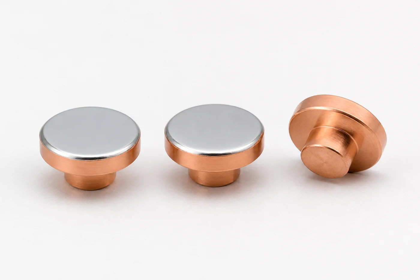
AC DC 전기접점 아크 소호
AC 아크는 접점이 벌어지는 즉시 사라지는 것이 아닙니다. 50 Hz에서는 약 10 ms마다, 60 Hz에서는 약 8.33 ms마다 전류영점이 나타나며 아크는 가장 가까운 전류영점까지 이어질 수 있습니다. 영점 직후 접점 간 절연 회복보다 회복전압의 상승이 빠르면 재점호도 발생합니다.
DC는 자연 전류영점이 없으므로 아크 길이를 늘리고 냉각해 아크전압을 회로전압보다 높여야 합니다. 접점 간격 확대, 빠른 개방, 직렬 이중 차단, 자석에 의한 아크 이동, 분할판과 밀폐가스가 사용되는 이유입니다. 저전류에서는 자기력이 충분하지 않아 자석만으로 아크가 안정적으로 이동하지 않는 구간도 있으므로 전류 범위 전체를 시험해야 합니다.
따라서 AC용 접점을 DC에 적용하거나, DC 정격을 단순한 전력값으로 환산하는 방식은 안전하지 않습니다. 제조사가 제시한 사용범주와 개폐전압·전류 곡선을 기준으로 선정하고, 실제 배선 인덕턴스와 보호회로를 포함한 완성 회로에서 차단을 확인해야 합니다.
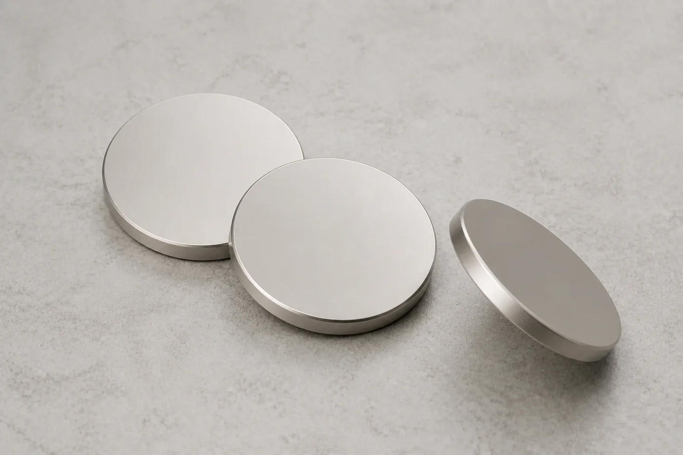
정격전류보다 부하 파형
접점 정격은 정상전류 하나로 설명되지 않습니다. 저항부하는 비교 기준이 되지만 모터·솔레노이드·변압기는 투입 시 돌입전류와 차단 시 역기전력이 발생합니다. LED 전원과 SMPS, 커패시터 뱅크는 짧고 큰 충전전류가 접촉면을 국부적으로 녹여 초기 용착을 만들 수 있습니다.
| 부하 | 투입 위험 | 차단 위험 | 도면·시험 입력값 |
|---|---|---|---|
| 저항부하 | 돌입이 비교적 작습니다. | 기준적인 아크 조건입니다. | 전압, 정상전류, 개폐빈도 |
| 모터·솔레노이드 | 기동·구속전류가 큽니다. | 저장에너지와 역기전력으로 아크가 길어집니다. | 피크전류, 지속시간, L/R 또는 역률 |
| LED·SMPS·커패시터 | 입력 커패시터 충전전류가 집중됩니다. | 잔류전압과 재투입 조건이 영향을 줍니다. | C, ESR, 배선저항, 프리차지 |
| 램프·히터 | 냉간저항이 낮아 돌입이 커질 수 있습니다. | 반복 투입에서 미세용착이 누적됩니다. | 냉간·열간 전류, 듀티비 |
AC는 투입 위상도 중요합니다. 일반 저항·램프·일부 용량성 부하는 전압영점 부근의 투입이 유리할 수 있지만, 철심이 있는 변압기와 솔레노이드는 잔류자속과 포화 때문에 같은 판단을 적용할 수 없습니다. 차단은 전압영점이 아니라 실제 부하전류의 영점과 접점 분리 시점을 기준으로 봅니다.
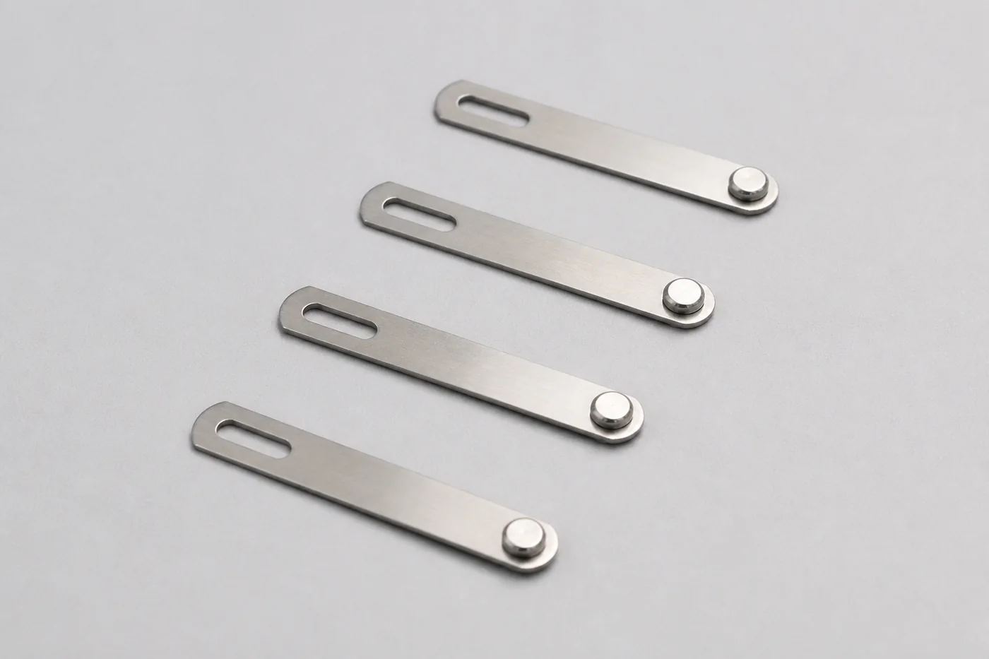
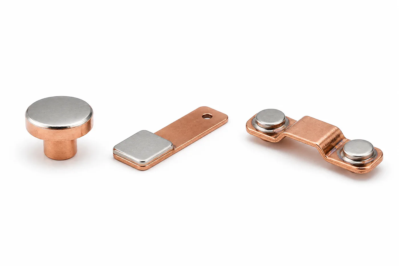
판형·리벳·브리지 접점 구조
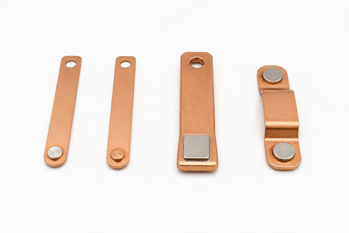
판형 접점 팁은 원형·사각·직사각의 은합금 또는 은-산화물 합금 팁을 동·동합금 캐리어의 평탄한 랜딩에 저항용접하거나 브레이징한 구조입니다. 봉재 절단, 프로파일·스트립 스탬핑, 분말 성형·소결로 팁을 만들 수 있으며 작동면에는 솔더나 용융 비드가 올라오지 않아야 합니다. 볼트로 체결하는 고전류 판대판 접촉과는 다른 구조입니다.
리벳접점은 은합금 작동 헤드와 동 생크가 한 축에 놓이는 솔리드·바이메탈·트라이메탈 구조입니다. 생크가 캐리어 구멍을 통과한 뒤 반대면에서 짧고 동심인 머리로 성형되어야 하며, 중공 팝리벳이나 나사 형상과 구분합니다. 필요한 작동면에만 귀금속을 사용해 재료 효율과 고속 조립성이 좋습니다.
브리지접점은 하나의 동 브리지가 두 고정 단자를 연결하는 이중 차단 구조입니다. 가동 브리지 아래의 두 팁과 고정 단자 위의 두 팁이 정확히 마주 보며, 개방 시 두 곳의 간격이 동시에 형성됩니다. 직렬 브레이크는 아크 길이와 절연거리를 늘릴 수 있지만 접촉압·동시성·간격 편차까지 관리해야 합니다.
| 구조 | 접합·조립 | 설계 강점 | 핵심 검사 |
|---|---|---|---|
| 판형 팁 | 저항용접·브레이징 | 두꺼운 마모여유와 고에너지 소재 적용 | 접합면 공극, 박리, 팁 높이 |
| 리벳접점 | 인서트 후 코이닝·리벳팅 | 귀금속 절감과 고속 양산 | 동심도, 머리 안착, 체결 균열 |
| 브리지접점 | 두 팁을 한 가동 브리지에 접합 | 이중 차단과 대전류 경로 | 좌우 압력, 간격, 동시 접촉 |
접촉압·간격·개방속도·바운스
접촉압은 실제 전류가 흐르는 미세 접촉점의 수와 면적을 결정합니다. 압력이 부족하면 수축저항과 온도상승이 커지고, 압력이 지나치면 스프링 피로와 접점 압흔, 마모 분진이 증가합니다. 도면에는 정적 접촉력뿐 아니라 오버트래블과 수명 후 최소 접촉력을 함께 정의하는 것이 좋습니다.
개방속도가 빨라지면 일반적으로 아크 지속시간은 짧아지지만 속도만 높이는 것으로 해결되지는 않습니다. 가동부 충격과 반발이 커지면 투입 바운스가 길어지고, 큰 돌입전류가 짧은 시간에 반복 차단되면서 미세용착이 완전용착으로 발전할 수 있습니다. 접촉압·가동질량·스프링 강성·감쇠를 하나의 기구계로 조정해야 합니다.
접점 간격은 최대 개방 위치의 거리만이 아니라 아크가 빠져나가는 경로와 주변 절연물의 오염까지 고려해 정합니다. DC 고전압에서는 두 접점을 직렬로 사용하더라도 제조사가 승인한 극성·배선·소호 구조를 따르지 않으면 정격이 자동으로 증가하지 않습니다.
DC 극성·재료이동·자기 소호
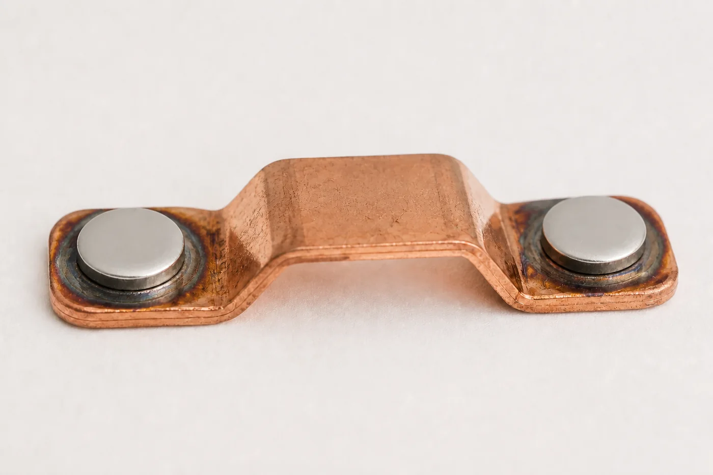
DC는 극성이 고정되기 때문에 반복 개폐에서 한 방향의 순재료이동이 누적되기 쉽습니다. 한쪽 접점에는 크레이터가, 반대쪽에는 돌기가 성장해 접점 높이와 간격, 접촉 위치가 달라질 수 있습니다. 다만 재료이동 방향은 용융 브리지, 아크 길이, 전류, 개방속도, 온도와 소재에 따라 바뀔 수 있으므로 음극에서 양극으로만 이동한다고 단정하지 않습니다.
영구자석식 자기 소호는 전류와 자기장에 의해 아크를 접점 밖으로 이동시킵니다. 단방향 접촉기에서는 지정된 전류방향에서 아크가 바깥쪽으로 벌어지도록 자석이 배치되며, 역방향에서는 아크가 중앙으로 모여 차단성능이 떨어질 수 있습니다. 회생과 충방전을 다루는 회로는 양방향 차단형인지 반드시 확인해야 합니다.
AC도 항상 재료이동이 상쇄되는 것은 아닙니다. 동일 위상에서 반복 개폐되거나 비대칭 파형이 형성되면 한쪽 방향의 손상이 누적될 수 있습니다. 극성, 투입 위상, 재점호 횟수, 아크 지속시간을 실제 파형으로 기록해야 접점 표면의 크레이터와 돌기 원인을 정확히 해석할 수 있습니다.
AC DC 전기접점 소재 선택
접점 소재는 AC·DC라는 구분만으로 선정하지 않습니다. 정상전류와 돌입전류, 아크에너지, 접촉압, 개폐빈도, 분위기, 허용 접촉저항을 함께 비교해야 합니다. 같은 AgSnO₂라도 산화물 함량과 입도, 첨가제, 제조법에 따라 접촉저항과 침식 거동이 달라집니다.
| 소재 | 강점 | 주의점 | 적용 방향 |
|---|---|---|---|
| AgNi | 낮고 안정적인 저항, 가공·용접성 | 강한 DC 유도부하에서 침식 증가 가능 | 범용 릴레이·접촉기 |
| AgSnO₂ | 고돌입 내용착성과 내아크성 | 산화물 분포와 첨가제에 따른 저항 차이 | 모터·램프·유도성 부하 |
| AgW | 높은 내아크침식·내용착성 | 접촉저항과 분말야금 비용 증가 | 보호기기·고에너지 판형 팁 |
| WCu·CuW | 매우 높은 아크침식 저항 | Ag계보다 상시 통전에 불리할 수 있음 | 중·고전압 아크접점 |
AgSnO₂가 모든 부하에서 AgNi보다 우수하거나, 판형 팁이 리벳접점보다 항상 오래간다는 식의 단순 비교는 피해야 합니다. 소재 단면의 공극과 2차상 분포, 작동면의 미세조직, 백킹과 접합부, 완성품의 실제 부하 수명 결과를 함께 확인해야 합니다.
아크 억제 회로와 적용 조건
DC 유도부하에는 플라이백 다이오드, 다이오드와 제너의 조합, TVS가 사용됩니다. 단순 다이오드는 과도전압을 낮추지만 솔레노이드의 해제시간을 늘려 기구 응답에 영향을 줄 수 있습니다. AC 유도부하는 RC 스너버나 MOV를 사용하며, 보호소자는 배선 인덕턴스가 작도록 부하 또는 접점 가까이에 배치합니다.
보호회로는 접점 아크를 줄이기 위한 회로이지만 잘못 적용하면 새로운 문제가 생깁니다. 큰 커패시터를 접점과 직접 병렬로 연결하면 투입 시 커패시터 방전전류가 접점으로 흘러 용착을 키울 수 있습니다. MOV·TVS의 클램프 전압이 너무 낮으면 부하 해제가 늦고, 너무 높으면 접점 과도전압이 충분히 억제되지 않습니다.
고전압 DC에서는 회로 보호소자와 함께 접점 간격, 더블 브레이크, 자기 소호, 아크 슈트, 밀폐가스를 시스템으로 설계합니다. 적용 전에는 최소·정격·최대 전류, 정방향·역방향, 저온·고온, 수명 초기·말기 조건에서 아크 지속시간과 과도전압을 비교해야 합니다.
- DC 유도부하: L/R, 해제시간, 클램프 전압을 함께 확인합니다.
- AC 유도부하: 역률과 실제 전류영점, 재점호를 확인합니다.
- 용량성 부하: 프리차지와 피크전류의 크기·폭을 측정합니다.
- 양방향 DC: 접촉기 극성과 양방향 차단 정격을 확인합니다.
AC DC 전기접점 수명시험
양산 승인은 초기 접촉저항 하나로 끝나지 않습니다. 실제 부하 파형에서 전기적 내구성을 시험하고, 개폐 중 바운스와 아크 지속시간, 접점 전압강하, 온도상승, 용착·고착, 수명 후 절연을 함께 판정해야 합니다. 샘플 수와 신뢰수준도 목표 수명과 고장 허용률에 맞춰 정합니다.
| 구분 | 기록 항목 | 판정 목적 |
|---|---|---|
| 부하 조건 | AC/DC, 전압, 정상·돌입전류, L/R, 역률, C·ESR | 시험 파형 재현 |
| 기구 특성 | 접촉압, 간격, 개방속도, 오버트래블, 바운스 | 아크·용착 원인 분리 |
| 전기 특성 | 4단자 저항, 전압강하, 온도상승, 과도전압 | 통전 성능과 발열 판정 |
| 아크·수명 | 아크시간, 재점호, 용착 횟수, 분리력, 수명분포 | 개폐 신뢰성 판정 |
| 수명 후 분석 | 크레이터·돌기, 질량손실, 박리, 탄화, 절연저항 | 고장모드와 공정 환류 |
릴레이와 접촉기는 IEC 61810 계열 또는 IEC 60947의 해당 사용범주를 기준으로 시험 틀을 정하되, 표준의 최소 조건만으로 실제 장치의 모든 부하를 대신할 수는 없습니다. 구매 사양서에는 접점재 명칭보다 실제 파형, 목표 전기수명, 허용 접촉저항, 용착 기준, 주변환경과 보호회로를 먼저 명확히 기록하는 것이 효과적입니다.
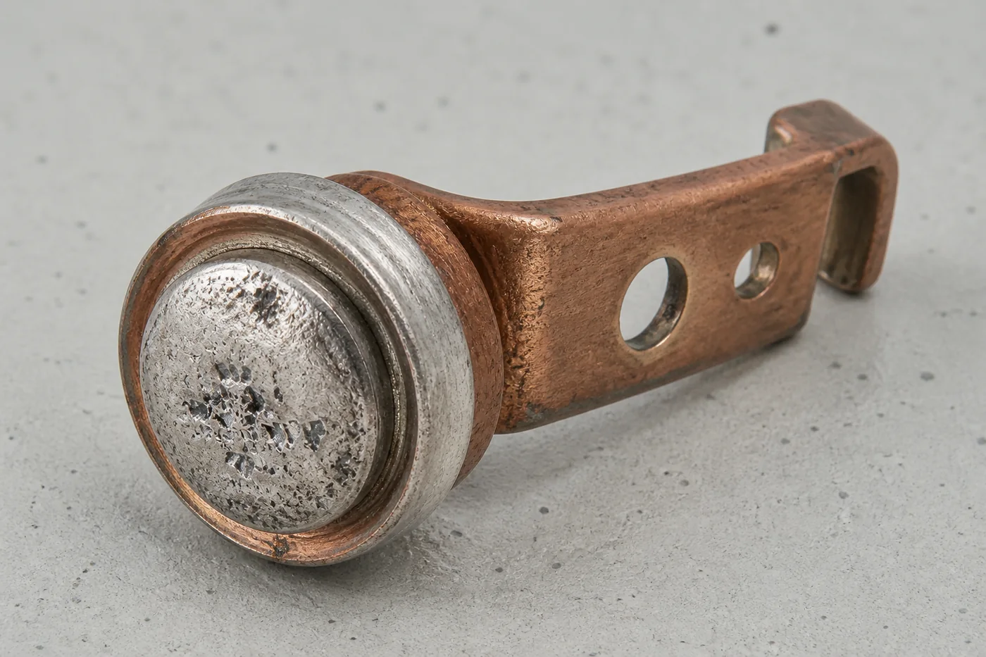
AC DC 전기접점 차이는 재료명 하나가 아니라 차단 메커니즘의 차이입니다. AC는 전류영점을 이용할 수 있지만 재점호와 돌입·바운스를 관리해야 하며, DC는 아크를 강제로 길게 만들고 냉각하는 구조와 극성 검증이 필요합니다.
판형 접점 팁, 리벳접점, 브리지접점은 각각 제조성과 전류경로가 다릅니다. 최종 선정은 접점 소재, 접합 품질, 접촉압, 간격, 속도, 보호회로를 실제 부하 수명시험으로 연결했을 때 완성됩니다.
English Technical Overview
AC and DC Electrical Contact Fundamentals
The difference between AC and DC electrical contacts is most pronounced when the load current is interrupted rather than during steady conduction. Here, AC and DC refer to the load current switched by the contacts, not to the relay-coil supply. Even at the same numerical value of 10 A, AC and DC impose different arc-extinction conditions and different thermal and electrical stresses on the contact system.
AC crosses zero every half-cycle, repeatedly giving the opening gap an opportunity to recover dielectric strength. DC has no natural current zero, so the current must be forced to extinguish through contact gap, opening speed, double-break geometry, magnetic blowout, arc chutes, and suppression circuits. An AC switching rating and a DC switching rating for the same relay are therefore not interchangeable.
Selection data must include more than voltage and continuous current. It should also define inrush current, the L/R ratio of inductive loads, AC power factor, capacitance and ESR, switching frequency, contact force, bounce, and ambient temperature. Plate-type contact tips, rivet contacts, and bridge contacts must be validated as complete systems that include material, joining method, current path, and arc-control structure under the actual load conditions.
Current Zero Crossing and Arc Extinction
An AC arc does not disappear immediately when the contacts separate. A current zero occurs approximately every 10 ms at 50 Hz and every 8.33 ms at 60 Hz, and the arc may persist until the nearest current zero. Restrike can occur after that zero if the transient recovery voltage rises faster than the dielectric strength of the opening gap recovers.
Because DC has no natural current zero, the arc must be lengthened and cooled until its arc voltage exceeds the circuit voltage. This is why DC switching devices use a larger contact gap, faster opening, two series breaks, magnetic arc displacement, splitter plates, and sealed-gas systems. At low current, however, the electromagnetic force may be insufficient to move the arc reliably with a magnet alone, so the entire specified current range must be tested.
It is therefore unsafe to apply an AC contact directly to a DC circuit or to derive a DC rating from a simple power calculation. Selection must follow the manufacturer’s utilization category and voltage-current switching curves, and interruption must be confirmed in the completed circuit, including its actual wiring inductance and suppression network.
Load Waveform Beyond Rated Current
A contact rating cannot be described by steady-state current alone. A resistive load is a useful reference, but motors, solenoids, and transformers generate inrush current at closing and counter electromotive force at opening. LED power supplies, switch-mode power supplies, and capacitor banks can produce a short, high charging-current pulse that locally melts the contact interface and initiates welding.
| Load | Make Risk | Break Risk | Drawing and Test Inputs |
|---|---|---|---|
| Resistive load | Inrush is comparatively low. | Provides a reference arc condition. | Voltage, steady-state current, switching frequency |
| Motor and solenoid | Starting and locked-rotor currents are high. | Stored energy and counter EMF extend the arc. | Peak current, duration, L/R ratio or power factor |
| LED, SMPS, and capacitor | Input-capacitor charging current is concentrated. | Residual voltage and re-energization conditions affect switching. | Capacitance, ESR, wiring resistance, precharge |
| Lamp and heater | Low cold resistance can cause high inrush. | Repeated energization can accumulate micro-welds. | Cold and hot current, duty cycle |
The closing phase is also important in AC circuits. Closing near a voltage zero may benefit conventional resistive loads, lamps, and some capacitive loads, but the same conclusion cannot be applied to transformers and solenoids with iron cores because of remanent flux and saturation. Break performance must be evaluated relative to the actual load-current zero and the instant of contact separation, not to the voltage zero.
Plate-Type, Rivet, and Bridge Contact Structures
A plate-type contact tip is a circular, square, or rectangular silver-alloy or silver-metal-oxide tip resistance-welded or brazed to a flat landing on a copper or copper-alloy carrier. Tips may be produced by cutting rod stock, stamping profile or strip material, or compacting and sintering powder. Solder or molten weld expulsion must not protrude onto the working face. This construction is distinct from a bolted, high-current plate-to-plate joint.
A rivet contact places a silver-alloy working head and a copper shank on a common axis in a solid, bimetal, or trimetal construction. After the shank passes through the carrier hole, it must be upset into a short, concentric rear head. It must be distinguished from a hollow blind rivet or a screw-shaped fastener. Precious metal is confined to the required working face, providing efficient material use and suitability for high-speed assembly.
A bridge contact is a double-break structure in which one copper bridge connects two stationary terminals. Two tips on the underside of the moving bridge must align precisely with two upward-facing tips on the stationary terminals, and two gaps must open simultaneously. Series breaks can increase arc length and dielectric distance, but contact force, synchronization, and gap variation must also be controlled.
| Structure | Joining or Assembly | Design Advantage | Critical Inspection |
|---|---|---|---|
| Plate-type tip | Resistance welding or brazing | Thick wear allowance and use of high-energy contact materials | Interfacial voids, delamination, tip height |
| Rivet contact | Insertion followed by coining or riveting | Precious-metal savings and high-speed production | Concentricity, head seating, fastening cracks |
| Bridge contact | Two tips joined to one moving bridge | Double break and high-current path | Left-right force balance, gap, simultaneous contact |
Contact Force, Gap, Opening Speed, and Bounce
Contact force determines the number and total area of microscopic spots through which current actually flows. Insufficient force increases constriction resistance and temperature rise, whereas excessive force increases spring fatigue, contact indentation, and wear debris. A drawing should define not only the static contact force but also overtravel and the minimum contact force after the specified service life.
Higher opening speed generally shortens arc duration, but speed alone does not solve the problem. If impact and rebound of the moving system increase, closing bounce becomes longer. A large inrush current can then be interrupted repeatedly within a short period, allowing micro-welds to develop into a complete weld. Contact force, moving mass, spring stiffness, and damping must be tuned as one mechanical system.
Contact gap is determined not only by the distance at maximum open position but also by the arc escape path and contamination of surrounding insulating components. In high-voltage DC applications, using two contacts in series does not automatically increase the rating unless the polarity, wiring, and arc-control arrangement approved by the manufacturer are followed.
DC Polarity, Material Transfer, and Magnetic Blowout
Because DC polarity is fixed, net material transfer in one direction can accumulate over repeated switching operations. A crater may grow on one contact while a protrusion develops on the other, changing contact height, gap, and the point of engagement. The transfer direction, however, can change with molten-bridge behavior, arc length, current, opening speed, temperature, and contact material, so it must not be stated categorically as transfer from cathode to anode.
Permanent-magnet blowout moves the arc away from the contact region through the interaction between current and magnetic field. In a unidirectional contactor, the magnets are arranged so that the arc is driven outward for the specified current direction. Reversing the current can instead drive the arcs toward the center and reduce interruption capability. Circuits that handle regenerative current or alternating charge and discharge must therefore be checked for an explicitly rated bidirectional breaking design.
Material transfer is not always cancelled in AC switching. If switching repeatedly occurs at the same phase or if the waveform is asymmetric, damage in one direction can accumulate. Polarity, closing phase, restrike count, and arc duration must be recorded from the actual waveforms to identify the causes of craters and protrusions on the contact surfaces correctly.
Selecting AgNi, AgSnO₂, AgW, and WCu
Contact material is not selected solely by whether the circuit is AC or DC. Steady-state current, inrush current, arc energy, contact force, switching frequency, atmosphere, and allowable contact resistance must be compared together. Even within AgSnO₂, contact resistance and erosion behavior vary with oxide content, particle size, additives, and manufacturing route.
| Material | Strength | Design Consideration | Application Direction |
|---|---|---|---|
| AgNi | Low, stable resistance with good formability and weldability | Erosion can increase under severe DC inductive loads | General-purpose relays and contactors |
| AgSnO₂ | Resistance to welding and arc erosion under high inrush | Resistance varies with oxide distribution and additives | Motor, lamp, and inductive loads |
| AgW | High resistance to arc erosion and welding | Higher contact resistance and powder-metallurgy cost | Protective devices and high-energy plate-type tips |
| WCu or CuW | Very high resistance to arc erosion | May be less favorable than silver systems for continuous conduction | Medium- and high-voltage arcing contacts |
Simple claims that AgSnO₂ is superior to AgNi for every load, or that a plate-type tip always lasts longer than a rivet contact, must be avoided. Qualification must examine voids and secondary-phase distribution in cross section, working-face microstructure, backing and joint integrity, and the electrical endurance result of the completed device under its actual load.
Arc-Suppression Circuits and Application Conditions
Flyback diodes, diode-zener combinations, and TVS devices are used for DC inductive loads. A simple diode reduces transient voltage but can lengthen solenoid release time and alter mechanical response. AC inductive loads use RC snubbers or MOVs. The protective component should be placed close to the load or contacts so that wiring inductance remains low.
A suppression circuit is intended to reduce contact arcing, but an incorrect implementation can introduce a new failure mechanism. Connecting a large capacitor directly across the contacts can discharge through them at closing and increase the risk of welding. If the clamp voltage of a MOV or TVS is too low, load release is delayed; if it is too high, the contact transient is not suppressed sufficiently.
In high-voltage DC systems, circuit suppressors are designed together with contact gap, double-break geometry, magnetic blowout, an arc chute, and sealed gas. Before release, arc duration and transient voltage must be compared at minimum, rated, and maximum current; in forward and reverse directions; at low and high temperature; and at the beginning and end of life.
- DC inductive load: Evaluate L/R, release time, and clamp voltage together.
- AC inductive load: Verify power factor, the actual current zero, and restrike.
- Capacitive load: Measure precharge conditions and the magnitude and width of the peak current.
- Bidirectional DC: Confirm contactor polarity and the bidirectional breaking rating.
Switching Life and Production Qualification Testing
Production qualification does not end with one initial contact-resistance measurement. Electrical endurance must be tested using the actual load waveform, while bounce, arc duration, contact voltage drop, temperature rise, welding or sticking, and post-life insulation are evaluated together. Sample size and confidence level should be selected to match the target life and allowable failure rate.
| Category | Recorded Parameters | Purpose |
|---|---|---|
| Load conditions | AC or DC, voltage, steady and inrush current, L/R, power factor, capacitance and ESR | Reproduce the test waveform |
| Mechanical characteristics | Contact force, gap, opening speed, overtravel, bounce | Separate the causes of arcing and welding |
| Electrical characteristics | Four-terminal resistance, voltage drop, temperature rise, transient voltage | Assess current-carrying performance and heating |
| Arc and life | Arc duration, restrike, weld count, separation force, life distribution | Assess switching reliability |
| Post-life analysis | Craters and protrusions, mass loss, delamination, carbonization, insulation resistance | Identify the failure mode and feed results back to the process |
IEC 61810 or the applicable IEC 60947 utilization category can define the test framework for relays and contactors, but the minimum conditions in a standard cannot represent every load in the actual device. A purchasing specification is most effective when it defines the real waveform, target electrical life, allowable contact resistance, welding criterion, environment, and suppression circuit before merely naming the contact material.
추가 정보
검색엔진용 요약
AC DC 전기접점 차이는 정상 통전보다 전류 차단 순간의 아크 소호 조건에서 크게 나타납니다. AC의 자연 전류영점과 DC의 연속 전류 특성, 부하 파형, 판형·리벳·브리지 접점 구조, 접점 소재, 보호회로와 개폐 수명시험을 함께 검토해야 정격 오적용과 접점 용착을 줄일 수 있습니다.
핵심 포인트 정리
- 릴레이 코일의 AC·DC 구분과 접점이 실제로 개폐하는 부하의 AC·DC 구분은 서로 다른 사양입니다.
- AC는 반주기마다 전류영점이 형성되지만 회복전압과 절연 회복 조건에 따라 재점호가 발생할 수 있습니다.
- DC는 자연 전류영점이 없으므로 접점 간격, 개방속도, 더블 브레이크, 자기 소호, 아크 슈트를 조합해야 합니다.
- 정격전류만 비교하지 않고 돌입전류, 역률 또는 L/R, 커패시턴스, 개폐빈도와 주위온도를 함께 확인해야 합니다.
- 판형 접점 팁·리벳접점·브리지접점은 소재명보다 접촉압, 오버트래블, 접합부, 방열과 소호 구조를 포함한 조립체로 평가해야 합니다.
- 양산 승인에서는 실제 부하 파형으로 접촉저항, 온도상승, 바운스, 아크 지속시간, 용착과 수명 후 절연을 검증해야 합니다.
FAQ
AC용 릴레이의 접점을 더 낮은 DC 전압에서 사용할 수 있습니까?
전압이 낮아도 제조사가 제시한 DC 개폐 정격이 없으면 바로 대체할 수 없습니다. DC 차단은 자연 전류영점이 없으므로 실제 전압과 전류, 부하의 L/R, 접점 구성, 극성, 보호회로를 기준으로 별도 확인해야 합니다.
릴레이 코일이 DC이면 접점도 DC용입니까?
코일 전원과 접점 부하 정격은 독립된 사양입니다. DC 코일을 사용하는 릴레이도 접점에는 AC와 DC 정격이 각각 표시될 수 있으며, 적용 판단은 접점이 실제로 개폐하는 회로의 부하 조건을 기준으로 합니다.
DC 접점의 재료이동 방향은 극성만으로 정할 수 있습니까?
고정 극성은 한쪽에 크레이터, 반대쪽에 돌기가 누적되는 방향성 마모를 만들 수 있지만 이동 방향을 항상 한 방향으로 일반화할 수는 없습니다. 소재 조합, 아크 길이, 전류, 온도, 개방속도와 브리지 전이에 따라 결과가 달라집니다.
판형 접점 팁과 리벳접점은 어떻게 구분합니까?
판형 접점 팁은 원형 또는 사각형 은합금 팁을 동계 캐리어에 용접하거나 브레이징한 구조입니다. 리벳접점은 작업면을 이루는 헤드와 캐리어 홀을 통과하는 축이 동축으로 연결되고, 뒤쪽 축을 업세팅해 고정하는 구조입니다.
DC 유도부하에 플라이백 다이오드를 적용하면 충분합니까?
다이오드는 과도전압과 접점 아크를 줄이는 데 효과적이지만 솔레노이드 해제시간을 늘릴 수 있습니다. 빠른 해제가 필요하면 다이오드·제너 조합이나 TVS를 검토하고, 클램프 전압과 해제시간, 접점 수명을 함께 측정해야 합니다.
전기접점의 수명 종료는 어떤 항목으로 판정합니까?
접촉저항 또는 전압강하의 증가, 온도상승, 용착·스티킹, 동작 불안정, 재점호, 절연저항과 내전압 저하를 함께 봅니다. 수명 후에는 접점 침식, 재료이동, 백킹 노출, 접합부 박리와 절연물 탄화도 확인해야 합니다.
관련 주제 확장 설명
투입 정격과 차단 정격
투입 순간에는 모터, 변압기, 램프, LED 드라이버와 커패시터 입력의 돌입전류가 접점 바운스와 겹칠 수 있습니다. 차단 순간에는 유도성 에너지와 회복전압이 아크 지속시간을 결정하므로 투입과 차단을 같은 전류값 하나로 평가해서는 안 됩니다.
브리지 접점과 더블 브레이크
브리지 접점은 하나의 가동 브리지가 두 고정 단자를 연결하고 개방 시 두 간극을 동시에 형성합니다. 아크 길이와 절연거리를 확보하는 데 유리하지만 좌우 접촉압, 간극, 동시성, 브리지 강성과 전류 경로가 균형을 이루어야 합니다.
정격표와 실제 부하 파형
정격표의 저항부하 수치는 실제 회로를 대표하지 않을 수 있습니다. 모터와 솔레노이드의 L/R, 변압기와 램프의 돌입, 스위칭 전원의 커패시터 충전전류, 보호소자의 클램프 특성을 측정 파형과 함께 검토해야 합니다.
내부 링크
ID METAL의 접점 제품과 적용 범위는 전기접점에서 확인할 수 있습니다. 판형 접점 캐리어와 단자 형상은 정밀프레스가공 부품, 리벳 고정과 체결 구조는 구조연결용 부품, 관련 제조 기술 글은 인사이트와 연결됩니다.
접점 소재 선정은 AgSnO₂ 미세조직과 아크 침식 제어, 저항 안정성은 전기접점 표면막과 접촉저항 관리, 양산 판정은 전기접점 신뢰성 검사 장비 체계, 조립 품질은 전기접점 리벳팅과 정밀가공에서 확장해 볼 수 있습니다.