
스타터 솔레노이드 접점: 고정단자·가동 접촉판의 재질과 제조 기술
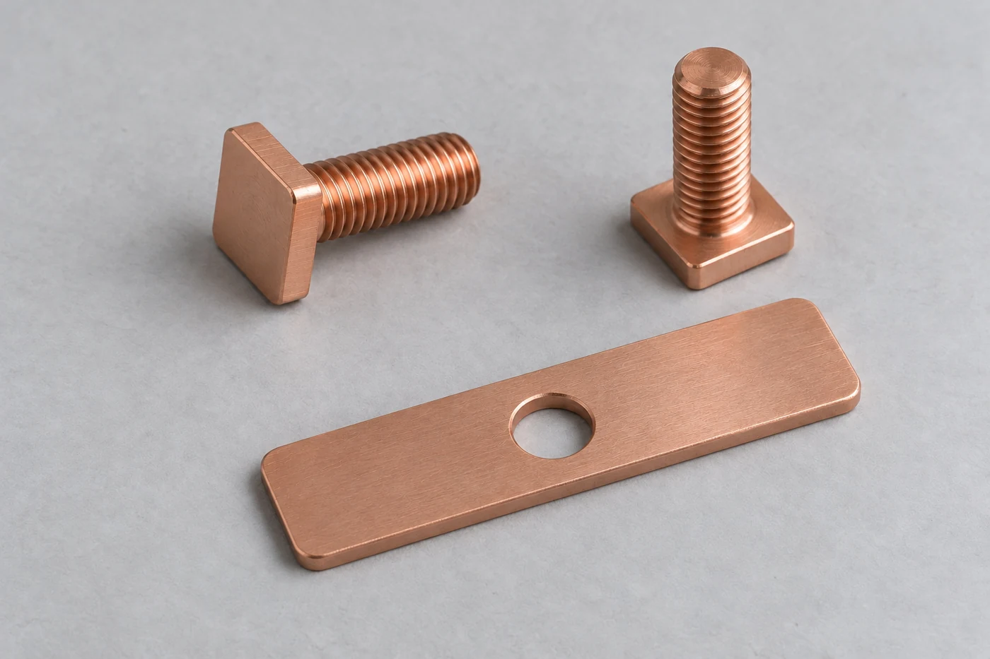
스타터 솔레노이드 접점은 배터리의 큰 전류를 시동모터에 연결하는 금속 접촉부품입니다. 두 고정단자 사이를 가동 접촉판이 연결하면 모터 회로가 닫히고, 접촉판이 떨어지면 전류 경로가 끊어집니다. 짧은 시동 시간에도 접촉면에는 큰 전류와 기계적 충격이 함께 작용하므로, 재질·접촉력·높이 정렬과 조립 상태가 시동 성능과 수명을 좌우합니다.
구리의 높은 전도도만으로 좋은 스타터 접점이 완성되지는 않습니다. 전류가 집중되는 실제 접촉부, 두 접촉면을 동시에 누르는 구조, 반복 동작으로 줄어드는 접촉 여유까지 함께 설계해야 합니다. 고정단자와 가동판의 정밀 제조는 낮은 통전 손실과 안정적인 개폐를 연결하는 핵심입니다.
01고정단자와 가동 접촉판의 통전 구조
스타터 솔레노이드의 주접점은 배터리측 고정단자, 모터측 고정단자, 두 단자를 잇는 가동 접촉판으로 구성됩니다. 가동판은 원판형 또는 브리지형 등으로 설계할 수 있으며, 닫힌 상태에서는 양쪽 접촉부를 거쳐 전류가 흐릅니다. 접점 두 곳이 나란히 보이더라도 전류가 반씩 나뉘는 병렬 구조가 아니라 한 경로에 이어지는 직렬 접촉부입니다.
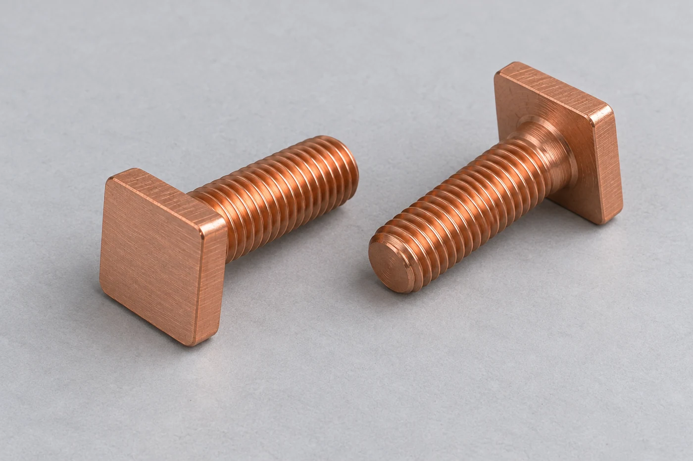
고정단자는 외부 케이블을 연결하는 나사부와 내부 접촉면을 하나의 부품으로 만들거나, 단자 볼트와 접촉편을 조합해 구성합니다. 가동판의 넓은 면은 상대 고정단자의 위치에 맞추어 통전 영역을 확보합니다. 외형 크기보다 두 접촉부의 실제 눌림 위치와 전류가 지나가는 최소 단면이 중요합니다.
| 구성부 | 주요 역할 | 제조·조립 관리점 |
|---|---|---|
| 배터리측 고정단자 | 배터리 전류 유입 | 나사·접촉면 위치, 체결 후 회전 방지 |
| 모터측 고정단자 | 모터로 전류 전달 | 접촉면 높이, 연결부 저항 |
| 가동 접촉판 | 두 고정단자를 전기적으로 연결 | 평면도·두께, 중심 지지와 접촉 균형 |
| 절연 전달부·접촉스프링 | 구동력 전달과 접촉력 형성 | 절연, 압축 높이, 이동 여유 |
코일과 플런저는 접촉판을 움직이는 구동계입니다. 주전류가 흐르는 접촉부와 구동축·금속 하우징 사이에는 필요한 절연이 있어야 합니다. 가동판을 금속 축에 단단히 고정하는 모양만으로 이해하면, 실제 설계의 절연부와 탄성 지지 기능을 놓치기 쉽습니다.
02흡인·유지·복귀의 작동 순서
일반적인 선행 맞물림식 스타터에서는 시동 신호가 솔레노이드에 들어오면 플런저가 이동하고, 레버를 통해 피니언을 링기어 방향으로 밀어냅니다. 이 이동과 연동하여 가동 접촉판이 두 고정단자에 닿고 모터의 주전류 경로가 연결됩니다. 전기 접촉 시점과 피니언 이동은 별개의 부품 움직임이지만 하나의 작동 순서 안에서 맞아야 합니다.
흡인 코일과 유지 코일을 사용하는 회로에서는 처음에 두 권선이 플런저를 끌어당기는 데 기여합니다. 주접점이 닫히면 흡인 권선 양단의 전위차가 작아지는 구성으로 흡인 전류가 줄고, 유지 권선이 플런저의 흡인 상태를 유지합니다. 실제 배선과 제어는 스타터 형식에 따라 달라지므로, 코일 구동회로와 모터 주전류 회로를 나누어 확인합니다.
피니언 치끝이 링기어 치끝과 만나는 경우에는 맞물림 스프링이 먼저 압축되고, 초기 회전으로 치형 위치가 맞춰지며 물림이 진행되는 구조도 있습니다. 따라서 모든 스타터의 동작을 “기어가 완전히 들어간 다음에만 접점이 닫힌다”는 한 문장으로 고정할 수 없습니다. 접점 부품의 평가에서는 기구에 요구되는 작동 위치와 전기적 닫힘 시점의 관계를 확인해야 합니다.
시동 명령이 해제되면 전자기력이 감소하고 복귀기구가 가동판을 고정접점에서 떼어 냅니다. 이때 전류가 끊기는 시점, 열린 상태의 간격, 피니언 복귀가 서로 맞아야 합니다. 스타터를 돌리는 주접점과 그 솔레노이드를 제어하는 작은 릴레이의 접점은 부하와 기능이 다릅니다.
03접촉스프링과 오버트래블
가동판이 고정단자에 처음 닿는 순간과 플런저의 최종 정지 위치는 같지 않습니다. 첫 접촉 이후에도 구동부가 조금 더 이동하면서 접촉스프링이 압축되고, 그 힘으로 두 접촉면이 눌립니다. 이 추가 이동량을 오버트래블 또는 접촉 여유로 관리합니다.
접촉 여유가 부족하면 새 부품에서는 통전하더라도 접촉면이 마모되거나 조립 높이가 변했을 때 눌림이 빠르게 감소합니다. 반대로 여유를 크게 만들면서 스프링을 과도하게 압축하면 흡인에 필요한 힘이 증가하고 부품 충격이나 기구 간섭이 커질 수 있습니다. 자유 길이만 같은 스프링을 바꾸어 넣어도 작동 높이에서의 하중이 다르면 접점 조건이 달라집니다.
접촉력은 접촉스프링만의 특성으로 끝나지 않습니다. 복귀스프링, 플런저 질량, 축 마찰, 자기회로의 힘과 움직이는 판의 강성이 함께 작용합니다. 설계 검토에서는 첫 접촉 위치, 최종 작동 위치, 그 사이의 힘 변화를 확인하고, 닫힘 유지와 명령 해제 후 복귀가 모두 가능한지 살펴야 합니다.
첫 접촉 이후 가동판의 위치는 두 고정면에 의해 제한됩니다. 구동부의 추가 이동은 접촉스프링과 지지부의 탄성변형으로 받아들이며, 이 구간의 힘·변위 관계가 접촉 여유와 작동 하중 검사의 기준이 됩니다.
화살표 키로 시점 조절
가동 접촉판이 고정 단자 두 개와 떨어져 있습니다. 구동부가 이동하면 접촉판이 두 기능면을 향해 내려갑니다.
절연 구동부의 추가 이동을 접촉스프링 압축으로 받아들이는 접촉부 구조
04접촉저항과 대전류 발열
금속면 두 개가 닿아도 전류는 겉으로 보이는 전체 면적에 고르게 흐르지 않습니다. 미세한 돌기들이 실제로 맞닿은 작은 영역에 전류가 집중되고, 표면 피막은 그 경로에 추가 저항을 만듭니다. 같은 구리 재질이라도 접촉력, 면의 평탄도, 산화·오염 상태가 달라지면 전압강하가 달라지는 이유입니다.
주접점 양단에서 측정한 전압강하에는 두 접촉 계면과 가동판·단자 내부의 저항이 함께 포함됩니다. 케이블 끝까지 측정 범위를 넓히면 외부 체결부와 전선의 손실도 더해집니다. 측정값을 “접점 저항”으로 비교하기 전에 전압 검출 위치부터 같게 해야 합니다.
| 전체 측정 경로의 저항 | 300 A 통전 시 전압강하 | 300 A 통전 시 저항 발열 |
|---|---|---|
| 0.2 mΩ | 0.06 V | 18 W |
| 0.5 mΩ | 0.15 V | 45 W |
| 1.0 mΩ | 0.30 V | 90 W |
표는 전류를 300 A로 고정했을 때의 산술 비교입니다. 실제 제품 정격이나 합격 기준이 아니라, 작은 밀리옴 차이가 대전류에서 만드는 영향을 보여줍니다. 같은 저항에서 전류가 두 배가 되면 저항 발열은 네 배가 되지만, 실제 온도상승은 통전 시간과 부품의 열용량·방열 경로까지 영향을 받습니다.
시동 직후에는 모터가 아직 충분히 회전하지 않아 큰 전류가 흐를 수 있습니다. 이 짧은 피크는 닫힘 충격과 바운스에 겹치고, 이어지는 크랭킹 구간은 누적 발열을 만듭니다. 최고 전류 하나만으로도, 평균 전류 하나만으로도 접점의 전기적 부담을 충분히 표현할 수 없습니다.
05양측 접촉면의 높이와 가동판 정렬
가동 접촉판이 한쪽 고정단자에 먼저 닿았다고 해서 주접점을 통한 대전류 경로가 완성되는 것은 아닙니다. 반대쪽 접촉부까지 연결되어야 두 단자를 잇는 직접 통전 경로가 생깁니다. 이후에도 한쪽 모서리에만 하중이 몰리면 보이는 접촉면 크기에 비해 실제 통전 영역은 작아집니다.
접촉면 높이 차이는 단자 자체의 치수뿐 아니라 절연 지지부의 안착, 체결 순서, 회전 방지 형상, 가동판 휨에서 발생할 수 있습니다. 도면의 기준면과 조립 상태를 연결해야 원인을 구분할 수 있습니다. 부품 단독 평면도만 확인하고 끝내면 체결 후 생긴 기울기를 놓칠 수 있습니다.
| 관리 항목 | 접촉에 미치는 영향 | 확인 방법 |
|---|---|---|
| 두 고정면의 상대 높이 | 첫 접촉 순서와 하중 분담 | 조립 기준면 대비 높이 측정 |
| 가동판 평면도·비틀림 | 편측 접촉과 국부 하중 | 자유 상태와 지지 상태 비교 |
| 중앙 지지·가이드 유격 | 자세 보정과 불필요한 흔들림 | 작동 위치별 움직임·간섭 확인 |
| 접촉 자국 위치 | 실제 눌림 영역의 편향 | 통제된 하중에서 접촉 흔적 비교 |
부동 지지나 제한된 기울기 허용은 양쪽 면에 안착하는 데 도움이 될 수 있지만, 큰 치수 오차를 무조건 흡수하는 기능은 아닙니다. 가동판의 허용 자세와 스프링 하중, 구동축 간섭을 함께 검토합니다. 접촉 자국은 정렬의 단서이며, 최종 전기 품질은 통전 중 전압강하와 반복 동작으로 연결해 평가합니다.
화살표 키로 시점 조절
가동 접촉판이 기울어져 있으면 두 고정 단자와의 간격이 다릅니다. 단자 높이, 접촉판 평탄도와 안내부의 여유가 접촉 순서에 영향을 줍니다.
가동판의 기울기에 따라 달라지는 첫 접촉 위치와 양측 안착 과정
06구리·고동합금·복합 접촉재의 선택
순동계 재료는 높은 전기·열전도도를 활용해 주전류를 전달하고 접촉부의 열을 주변으로 확산시키는 데 유리합니다. 다만 재료명만으로 경도와 변형 저항이 정해지는 것은 아닙니다. 가공경화와 열이력에 따라 상태가 달라지므로, 접촉면의 눌림과 단자 체결을 버텨야 하는 부위는 조질까지 지정해야 합니다.
강도와 고온에서의 형상 유지가 더 필요하면 고동합금의 특성을 비교합니다. CuZr·CuCrZr 계열 등은 전도도와 기계적 성질을 함께 조정하는 소재군이지만, 특정 합금명을 모든 스타터의 표준으로 볼 수는 없습니다. 판재·봉재의 공급 상태, 성형성, 접합 후 경도 변화와 전도도를 함께 평가해야 합니다.
| 재료 구성 | 주요 검토 목적 | 함께 확인할 항목 |
|---|---|---|
| 순동계 접촉부·도체 | 통전 손실과 열 분산 | 조질, 접촉면 변형, 침식·용착 |
| 고동합금 도체 | 전도도와 기계적 안정성의 균형 | 합금·열처리 상태, 성형성, 접합 열이력 |
| Cu-W 등 복합 접촉재 | 접촉 영역의 내아크·침식 특성 조정 | 조성·조직, 접촉저항, 접합부와 방열 |
| 기능재를 붙인 복합 구조 | 도체부와 접촉부의 기능 분담 | 기능층 위치·두께, 계면, 가공 후 노출 |
구리-텅스텐(Cu-W)과 같은 복합 접촉재는 전도성을 담당하는 상과 높은 내열성을 가진 상을 결합합니다. 접촉부 손상 억제를 검토할 수 있지만, 전도도·접촉저항·열 분산과 접합성도 달라집니다. 재질을 바꾸어 침식이 줄어도 통전 중 발열이 늘 수 있으므로, 접점 수명과 온도상승을 따로 확인합니다.
은계 접촉재를 쓰는 다른 전기기기의 경험을 스타터에 그대로 옮겨서는 안 됩니다. 은 함량이나 외관 색상만으로 성능을 순위화하기보다 실제 기동 전류 파형, 개폐 전류, 접촉력, 요구 수명에 맞춰 재료와 형상을 조합해야 합니다. 표면 도금과 하중을 받는 기능 접촉층도 구분해 도면에 표시합니다.
07접촉면 가공과 표면 상태
접촉면의 가공 목적은 광택 자체가 아니라 안정적으로 눌리는 형상과 재현 가능한 표면 상태를 만드는 데 있습니다. 국부 돌기, 깊은 흠, 버가 실제 접촉 영역에 남으면 하중과 전류가 좁은 곳에 집중될 수 있습니다. 반대로 외관을 매끈하게 보이게 하려고 과도하게 연마하면 접촉 높이와 기능층 두께가 바뀔 수 있습니다.
구리계 표면은 보관과 사용 환경에서 산화되며, 가공유·연마 잔류물·취급 오염도 접촉 상태에 영향을 줍니다. 세척 조건은 재료와 표면처리에 맞추고, 건조 후 재오염과 부품끼리의 충돌을 줄이는 포장이 이어져야 합니다. 표면이 밝게 보인다는 이유만으로 전기적 청정도를 판단하지 않습니다.
외부 단자와 내부 개폐면은 필요한 표면 기능이 다를 수 있습니다. 도금 사양을 정할 때에는 도금 구역, 바탕층, 두께와 허용 노출부를 나누고, 접촉면의 높이 변화까지 검토합니다. 접촉면 전체를 일률적으로 도금하는 방식이 언제나 유리한 것은 아닙니다.
선정한 표면 상태는 출하 직후뿐 아니라 보관 후와 반복 개폐 후에도 비교합니다. 초기 산화막을 강한 시험전류가 변화시킨 뒤 측정하면 입고 상태의 문제를 놓칠 수 있으므로, 검사 목적에 따라 시험 순서와 전류 조건을 고정해야 합니다.
08고정단자와 가동판의 성형·가공
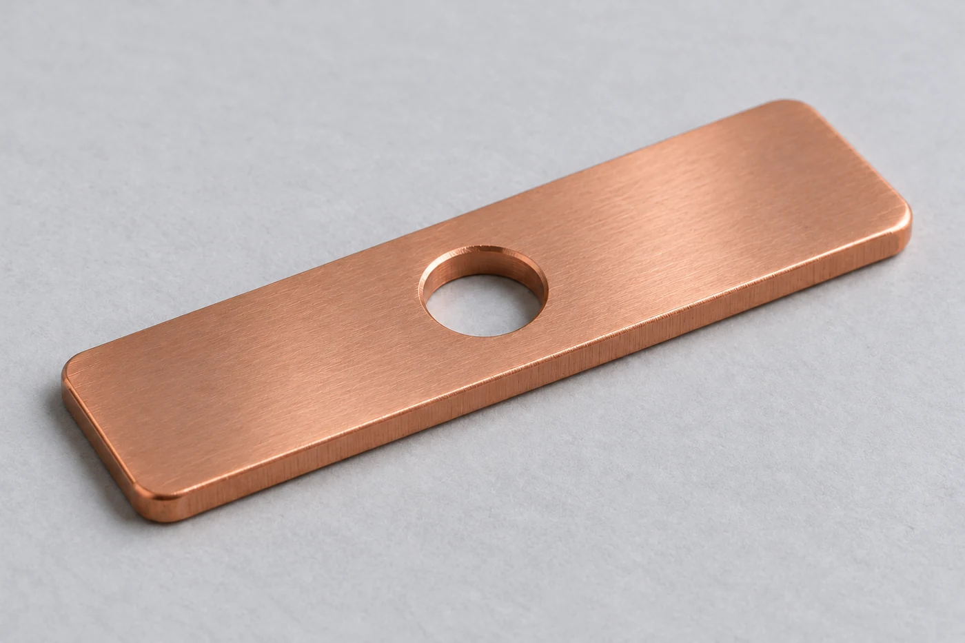
얇거나 일정 두께의 가동 접촉판은 판재 블랭킹과 후속 성형을 검토할 수 있습니다. 외곽과 중심 구멍을 만든 뒤 기능면을 교정하거나 코이닝하여 높이와 국부 형상을 관리합니다. 금형 간극, 공구 마모, 소재 조질이 바뀌면 절단면과 휨도 함께 달라집니다.
큰 나사부와 두꺼운 접촉부를 가진 고정단자는 판재 프레스만으로 설명하기 어렵습니다. 형상에 따라 냉간 성형·단조와 절삭을 조합하거나, 별도의 접촉편을 단자부에 접합하는 경로를 검토합니다. 공정은 외형뿐 아니라 재료 흐름, 기능면 위치, 최소 통전 단면과 수량에 맞추어 정합니다.
| 공정 단계 | 주요 관리점 | 다음 공정에 미치는 영향 |
|---|---|---|
| 소재 준비 | 합금·조질, 두께와 공급 방향 | 성형 하중과 변형 균일성 |
| 블랭킹·피어싱 | 금형 간극, 버 방향, 구멍 위치 | 가이드 맞춤과 절연부 손상 위험 |
| 성형·코이닝·교정 | 기준면, 하중, 복원과 잔류 휨 | 양측 접촉 높이와 판의 자세 |
| 나사·기능면 가공 | 동심도·위치, 가공면과 모서리 | 체결 안정성과 접촉부 정렬 |
| 세척·최종 검사 | 잔류물, 변형, 소재 추적 | 조립과 전기 검사 재현성 |
중앙 구멍 가장자리의 버는 절연 부시를 손상시키거나 가동판의 자유로운 움직임을 방해할 수 있습니다. 반대로 과도한 디버링은 구멍 크기와 지지면을 바꿉니다. “버 없음”이라는 포괄적 표현에 그치지 않고 접촉면·가이드부·절연 접촉부별로 모서리 상태와 허용 범위를 지정하는 편이 유리합니다.
재질 변경이나 열처리 후에는 동일 금형을 썼다는 이유로 이전 결과를 그대로 인정할 수 없습니다. 성형 뒤 경도, 기능면 높이와 가동판 휨을 다시 연결해 확인합니다. 최종 접촉 상태를 만드는 공정까지 포함해 치수와 물성을 관리해야 합니다.
09접합·절연 지지와 조립 기준
접촉 기능재를 도체에 붙이는 구조에서는 접촉면과 접합 계면을 구분합니다. 브레이징·용접·기계적 결합 중 어떤 방식을 쓰더라도 계면이 주전류와 열을 전달할 수 있어야 합니다. 겉에서 보이는 접합 폭만으로 내부의 미접합, 공극이나 국부 열집중을 판단하기는 어렵습니다.
접합 열이력은 동계 모재의 경도와 평탄도에 영향을 줄 수 있습니다. 기능재를 붙이기 전에 치수가 맞았더라도 가열·냉각 후 접촉면 높이가 변할 수 있으므로, 최종 기준면은 접합 뒤 검사에 연결합니다. 필요하면 단면 분석과 접합 강도, 전기저항의 조합으로 공정을 평가합니다.
조립에서는 두 고정단자가 절연 지지부에 정해진 방향과 높이로 안착해야 합니다. 체결 토크는 부품을 잡아 두는 힘을 만들지만, 과도한 힘은 절연부 변형이나 접촉면 기울기를 만들 수 있습니다. 회전 방지 형상과 체결 순서를 정하고, 단자 외부의 케이블 하중이 내부 정렬을 바꾸지 않는지도 확인합니다.
가동판·절연 전달부·스프링은 개별 부품이 맞는 것에 더해 조립 후 자유롭게 움직여야 합니다. 간극이 좁으면 열팽창이나 미세 입자에 의해 걸림이 생기고, 지나치게 넓으면 기울기와 충격이 커질 수 있습니다. 분해 3D에서 각 부품의 역할을 확인한 뒤, 완성 조립체의 작동 위치와 힘을 기준으로 판정해야 합니다.
화살표 키로 시점 조절
두 고정 단자와 가동 접촉판이 주전류 경로를 구성합니다. 절연 지지부와 절연 구동부는 이 경로를 기계적인 구동계와 분리합니다.
고정 단자, 가동 접촉판, 절연 지지부와 접촉스프링의 조립 관계
10바운스·침식·용착의 손상 경로
접점이 닫힐 때 가동판이 고정면에서 순간적으로 튀어 오르면 전류가 흐르다가 다시 끊기는 짧은 개폐가 반복됩니다. 이를 접점 바운스라고 합니다. 시동 초기의 큰 전류와 겹치면 국부 용융과 아크 손상이 늘어나며, 다시 맞닿은 용융부가 굳으면 용착으로 이어질 수 있습니다.
기계적 충격에 의한 짧은 바운스와 코일 전압 부족으로 솔레노이드가 반복 흡인·복귀하는 채터링은 구분해야 합니다. 배터리나 배선의 전압강하가 큰 경우에도 접점이 불안정해질 수 있습니다. 접촉재만 바꾸기 전에 코일 전압, 플런저 움직임과 주전류 파형을 함께 보는 이유입니다.
| 관찰된 현상 | 가능한 원인 경로 | 추가 확인 |
|---|---|---|
| 접촉면의 국부 파임·돌기 | 아크 침식과 재료 이동 | 좌우·극성별 손상 위치, 전류 파형 |
| 닫힌 상태에서 분리되지 않음 | 국부 용착 또는 기구 걸림 | 분리력, 접촉면, 축·가이드의 이물 |
| 반복 흡인과 복귀 | 공급전압 부족, 제어 경로 손실 | 코일 양단 전압과 배선 상태 |
| 누적 작동 후 닫힘 불안정 | 접촉면 마모, 스프링·가이드 변화 | 남은 접촉 여유, 작동력과 변위 |
접촉면에서 떨어져 나온 금속 입자는 접점의 손실량에만 머물지 않습니다. 가이드나 플런저 쪽으로 이동하면 마찰을 높이고 최종 스트로크를 막을 수 있습니다. 접촉부와 구동부 사이의 차폐, 입자가 머무는 공간, 설치 방향까지 수명 설계에 연결됩니다.
표면의 변색이나 사진 한 장만으로 용착·산화·과열을 확정하지 않습니다. 손상 형태와 함께 전압강하 변화, 접촉 높이 감소, 복귀 불량의 발생 시점을 비교해야 합니다. 이렇게 원인을 나누어야 재질 변경, 성형 교정, 스프링 조정, 오염 관리 중 필요한 대책을 고를 수 있습니다.
11전압강하·접촉력·동작 파형의 검사
측정 경로와 검사 순서
작은 저항을 비교할 때에는 전류를 흘리는 선과 전압을 읽는 선을 분리하는 4선식 측정이 유리합니다. 전압 검출점을 관리하지 않으면 케이블과 클램프의 저항이 부품 차이처럼 보일 수 있습니다. 시험 전류, 접촉 상태, 측정 시간과 온도를 함께 기록해 반복 측정이 같은 조건에서 이루어지도록 합니다.
표면 피막을 유지한 상태를 보는 저에너지 측정과 실제 통전 성능을 보는 부하 전압강하 시험은 목적이 다릅니다. 저에너지 검사는 입고 표면 상태를 비교하는 데 사용할 수 있지만, 스타터의 대전류 개폐 성능을 대신하지 않습니다. 반대로 먼저 큰 전류를 흘리면 표면 상태가 변할 수 있으므로 검사 순서를 정해야 합니다.
| 검사 | 주요 측정값 | 해석 기준 |
|---|---|---|
| 치수·정렬 | 기능면 높이, 판 두께·휨, 기준 위치 | 조립 상태에서 양면 안착 가능 여부 |
| 힘·변위 | 첫 접촉 위치, 작동 높이 하중, 복귀 | 가동 여유와 스프링 하중의 일관성 |
| 전기·열 | 정해진 구간 전압강하, 전류, 온도 | 주변 배선 손실과 접점 손실 분리 |
| 동적 개폐 | 코일 전압·전류, 접점 전압, 주전류 | 바운스·채터링·지연의 발생 순서 |
동작 파형과 온도 측정
바운스 검사는 접점 전압과 주전류를 충분한 시간 해상도로 동시에 기록해야 합니다. 느린 평균값만 저장하면 짧은 분리가 사라져 정상처럼 보일 수 있습니다. 트리거 기준과 샘플링·대역폭을 예상 이벤트 길이에 맞추고, 무부하 기계 동작과 실제 부하 개폐를 구분해 비교합니다.
온도 검사는 접촉면, 단자, 절연부 등 측정 위치를 고정합니다. 광택 금속의 열화상은 방사율과 주변 반사에 영향을 받으므로 접촉식 센서와의 대조 등으로 읽는 값을 확인합니다. 센서 부착 자체가 열 흐름이나 기구 움직임을 바꾸지 않도록 하는 것도 시험 설계의 일부입니다.
개발 단계에서 단품과 조립체를 함께 측정하면 치수 불량과 작동 불량의 연결이 보입니다. 예를 들어 단품 높이는 정상인데 조립 후 전압강하가 한쪽에 집중되면 지지·체결 상태를 먼저 확인할 수 있습니다. 검사값은 합격 표시만 남기기보다 부품 로트와 조립 조건에 연결해 저장하는 편이 원인 추적에 유리합니다.
12반복 시동과 환경 내구
스타터 접점의 수명시험은 단순히 닫았다 여는 횟수를 세는 시험이 아닙니다. 투입 순간의 전류, 크랭킹 구간의 전류와 시간, 개방 시 남는 전류, 휴지 시간을 함께 정해야 합니다. 같은 횟수라도 짧은 간격으로 반복하면 열이 충분히 빠져나가지 않아 다른 결과가 나올 수 있습니다.
자동 정차·재시동 기능은 접점의 반복 횟수와 작동 조건을 바꿉니다. 최초 냉간 시동과 주행 중 재시동은 배터리 상태, 엔진 저항, 부품 온도가 같지 않습니다. 목표 사용 조건을 대표하는 여러 구간을 구성하고, 접점 마모와 구동부 마찰이 어느 시점에서 증가하는지 확인합니다.
저온에서는 윤활·기구 저항과 배터리 공급 능력이, 고온에서는 코일 저항과 재료의 강성·스프링 특성이 작동 여유에 영향을 줄 수 있습니다. 주변 온도만 설정하고 전원 조건이나 부품의 열평형을 통제하지 않으면 시험 간 비교가 흔들립니다. 냉간·열간 상태의 흡인, 유지, 복귀 조건을 나누어 기록합니다.
진동과 충격은 닫힌 접촉부의 순간 분리뿐 아니라 열린 상태의 원치 않는 접촉에도 영향을 줄 수 있습니다. 습기와 오염은 표면 피막, 절연 상태와 부식에 연결됩니다. 적용 위치의 환경을 반영해 시험하고, 시험 뒤 전기적 특성과 기계적 복귀가 모두 유지되는지 평가합니다.
마지막 판정에는 통전 저항뿐 아니라 용착, 미복귀, 접촉 여유 감소, 절연 이상과 이물 이동을 포함합니다. 수명 중간에 정해진 간격으로 검사하면 마지막 고장만 보는 것보다 열화 속도를 파악하기 쉽습니다. 재질이나 공정을 바꾼 시료는 같은 회로·기구 조건에서 비교해야 개선 효과를 분리할 수 있습니다.
13도면 사양과 양산 품질관리
스타터 솔레노이드 접점 도면에는 외형과 나사 치수뿐 아니라 통전면, 지지면, 절연면의 기능 구분이 필요합니다. 조립 기준면에서 두 고정면까지의 높이, 가동판의 평면도와 허용 기울기, 중심 가이드와의 간극이 접촉 상태로 이어져야 합니다. 재질은 합금명에 조질과 기능층·표면처리 구역까지 연결합니다.
| 도면·사양 항목 | 함께 정할 내용 |
|---|---|
| 재료와 상태 | 합금·조성, 조질, 열이력, 기능층 유무 |
| 접촉 기하 | 기준면, 접촉 높이, 평면도, 모서리와 버 방향 |
| 조립 조건 | 체결 순서·토크, 절연 지지, 스프링 작동 높이 |
| 전기·열 기준 | 측정점, 시험 전류·시간, 전압강하와 온도 판정 |
| 동작·수명 조건 | 공급 전압, 투입·개방 파형, 반복·휴지 시간, 실패 정의 |
| 변경·추적 관리 | 소재 로트, 금형·가공·접합 조건, 변경 승인 범위 |
양산에서는 소재 경도와 두께, 금형 마모, 기능면 높이, 조립 하중을 연결해 관리합니다. 최종 검사만 강화하기보다 앞 공정에서 변동이 생기는 지점을 확인해야 불량 원인을 줄일 수 있습니다. 동일한 접점 형상이라도 소재 공급 상태나 접합 공정이 바뀌면 검증 범위를 다시 정합니다.
고정단자와 가동 접촉판의 품질은 낮은 저항, 안정된 접촉력, 정확한 조립, 반복 동작 후의 복귀가 함께 충족될 때 평가할 수 있습니다. 접촉재의 이름이나 표면 광택보다 실제로 맞닿는 상태와 사용 중 남는 여유를 설계·제조·검사로 이어 주는 것이 중요합니다.
제작 검토에는 단품 도면과 함께 상대 접점 형상, 조립 단면, 작동 높이와 하중, 전류 조건을 준비하면 도움이 됩니다. 필요한 기능을 기준으로 소재와 공정을 정리하면 외형이 같은 부품 사이에서도 어떤 차이를 관리해야 하는지 명확해집니다.
Starter Solenoid Contacts: Materials and Manufacturing of Fixed Terminals and Moving Contact Bridges
Starter solenoid contacts are metal components that connect the high current from the battery to the starter motor. A moving contact bridge closes the motor circuit by connecting two fixed terminals; separating the bridge interrupts that path. Even during a short start, the contact faces experience high current and mechanical impact together, so material, contact force, height alignment and assembly condition influence starting performance and service life.
Copper’s high conductivity alone does not produce a reliable starter contact. The actual spots carrying current, the mechanism pressing both contact faces together and the contact travel remaining after repeated operation all need to be designed together. Precision manufacture of the fixed terminals and moving bridge connects low conduction loss with stable switching.
01Current Path through Fixed Terminals and the Moving Bridge
The main contacts of a starter solenoid comprise a battery-side fixed terminal, a motor-side fixed terminal and a moving contact member that bridges them. The moving member may be a disc or a bridge, with current passing through both contact interfaces when closed. Although the two contact zones appear side by side, they are interfaces in series along one current path, rather than parallel paths sharing half the current each.
A fixed terminal can integrate the external threaded connection and internal contact face, or combine a terminal bolt with a separate contact piece. The broad moving face provides a contact region aligned with the opposing terminals. The actual loaded locations and the smallest current-carrying cross-section matter more than the overall outline alone.
| Component | Function | Manufacturing and assembly controls |
|---|---|---|
| Battery-side terminal | Receives battery current | Thread and face location; resistance to rotation after tightening |
| Motor-side terminal | Transfers current to the motor | Contact height; connection resistance |
| Moving bridge | Electrically joins the fixed terminals | Flatness and thickness; central support and balanced seating |
| Insulating linkage and contact spring | Transmit motion and establish contact force | Insulation; compressed height; travel allowance |
The coil and plunger form the actuator that moves the bridge. Appropriate insulation is needed between the high-current contact system and the drive shaft or metal housing. Treating the bridge simply as a metal plate rigidly fixed to a shaft overlooks the insulation and compliant support present in the actual design.
02Pull-in, Holding and Return Sequence
In a conventional pre-engaged starter, a start signal energizes the solenoid, moving the plunger and driving the pinion toward the ring gear through a lever. During this coordinated motion, the moving bridge touches both fixed terminals and establishes the motor’s main current path. Electrical closure and pinion movement involve different parts but must fit the same operating sequence.
In circuits using pull-in and hold-in windings, both windings initially contribute to attracting the plunger. Once the main contacts close, a configuration that reduces the voltage difference across the pull-in winding reduces its current, while the hold-in winding keeps the plunger pulled in. Wiring and control vary by starter type, so the coil drive circuit and the motor’s main-current circuit should be checked separately.
If the pinion tooth meets a ring-gear tooth, some mechanisms first compress a meshing spring and then complete engagement as initial rotation aligns the teeth. It is therefore inaccurate to impose a universal rule that contacts close only after full gear engagement. Contact-part evaluation must establish the relationship between the required mechanical position and electrical closure.
When the start command ends, electromagnetic force decreases and the return mechanism separates the bridge from the fixed contacts. Current interruption, the open gap and pinion return must remain coordinated. The main contacts supplying the starter motor have a different duty from the contacts of the smaller relay controlling its solenoid.
03Contact Spring and Overtravel
The position at which the moving bridge first touches the fixed terminals is different from the plunger’s final stop. Further actuator movement compresses the contact spring, which presses the two contact interfaces together. This additional motion is controlled as overtravel or contact follow.
With insufficient follow, a new part may conduct properly but quickly lose force as the contact surfaces wear or the assembly height changes. Excessive spring compression introduced to increase follow can instead raise pull-in force, impact or interference. Replacing a spring with one having the same free length still changes contact conditions if its load at working height differs.
Contact force is not determined by the contact spring in isolation. The return spring, plunger mass, shaft friction, magnetic force and moving-plate stiffness act together. A design review should examine first-touch position, final operating position and the force change between them, while confirming both closed-state retention and return after the command ends.
After first touch, the two fixed contact faces constrain the position of the moving bridge. Further actuator travel is accommodated by elastic deformation of the contact spring and support. The force–displacement relationship over this interval provides the basis for checking contact follow and operating load.
Arrow keys change the view
The moving bridge is separated from both fixed terminals. Drive movement lowers the bridge toward the two functional faces.
Additional drive movement is accommodated by compression of the contact spring
04Contact Resistance and High-current Heating
When two metal faces touch, current does not flow uniformly across their entire visible area. It concentrates through small regions where microscopic asperities actually meet, while surface films add resistance to that path. This explains why identical copper grades can show different voltage drops when contact force, flatness, oxidation or contamination differs.
Voltage measured across the main terminals includes both contact interfaces and the bulk resistance of the bridge and terminals. Extending the measurement to cable ends also includes external joints and wiring losses. Voltage-sense locations must therefore be identical before values are compared as contact resistance.
| Resistance of the measured path | Voltage drop at 300 A | Resistive heating at 300 A |
|---|---|---|
| 0.2 mΩ | 0.06 V | 18 W |
| 0.5 mΩ | 0.15 V | 45 W |
| 1.0 mΩ | 0.30 V | 90 W |
The table is an arithmetic comparison at a fixed current of 300 A. It illustrates the effect of small milliohm differences at high current; it does not specify a product rating or acceptance limit. Doubling current at the same resistance quadruples resistive heating, while actual temperature rise also depends on duration, thermal capacity and heat-removal paths.
High current can flow immediately after starting because the motor has not yet reached appreciable speed. This brief peak coincides with closing impact and bounce, while the following cranking interval produces accumulated heating. Neither peak current alone nor average current alone fully describes the electrical duty imposed on the contacts.
05Fixed-contact Height and Bridge Alignment
The high-current path through the main contacts is not complete merely because the moving bridge touches one fixed terminal first. The opposite interface must also connect to establish the direct conducting path between the two terminals. Even then, concentrating the load on one edge leaves the actual conducting area small relative to the visible face.
Height mismatch can arise from terminal dimensions, seating of insulating supports, tightening sequence, anti-rotation features or bridge distortion. Drawing datums must be related to the assembled condition to distinguish these causes. Checking part flatness alone can miss tilt introduced by assembly.
| Control | Effect on contact | Check |
|---|---|---|
| Relative height of fixed faces | First-touch sequence and load sharing | Height measured from the assembly datum |
| Bridge flatness and twist | One-sided contact and local loading | Compare free and supported conditions |
| Central support and guide clearance | Seating adjustment and unwanted movement | Motion and interference at operating positions |
| Location of contact marks | Bias in the loaded region | Compare marks under controlled loading |
Floating support or limited permitted tilt can help both faces seat, but cannot absorb arbitrary dimensional error. The allowed bridge attitude must be considered together with spring load and drive-shaft interference. Contact marks provide evidence of alignment; final electrical quality requires correlation with voltage drop under load and repeated operation.
Arrow keys change the view
A tilted bridge has different gaps at the two terminals. Terminal height, bridge flatness and guide clearance influence the order of contact.
Bridge tilt changes the first contact location and the sequence of two-sided engagement
06Copper, High-copper Alloys and Composite Contact Materials
Pure-copper materials offer high electrical and thermal conductivity for carrying the main current and spreading heat away from contact regions. Material designation alone, however, does not define hardness or resistance to deformation. Work hardening and thermal history change the condition, so temper must also be specified where contact indentation and terminal tightening loads are important.
High-copper alloys are compared when greater strength or shape retention at elevated temperature is needed. Families such as CuZr and CuCrZr adjust conductivity and mechanical properties together, but no single grade is a universal starter specification. Supply condition of strip or bar, formability, changes in hardness after joining and conductivity must be considered together.
| Material arrangement | Purpose | Additional checks |
|---|---|---|
| Pure-copper contacts and conductors | Low conduction loss and heat spreading | Temper; face deformation; erosion and welding |
| High-copper-alloy conductors | Balance of conductivity and mechanical stability | Alloy and heat treatment; formability; joining heat cycle |
| Composite contacts such as Cu-W | Adjust arc and erosion behavior at the contact region | Composition and structure; resistance; joint and heat path |
| Composite construction with functional contact material | Separate conductor and contact functions | Layer location and thickness; interface; exposure after processing |
Copper-tungsten composites combine a conducting phase with a refractory tungsten phase. They can be considered to reduce contact damage, but conductivity, contact resistance, heat flow and joinability also change. Reduced erosion after a material change can coexist with greater conduction heating, so switching life and temperature rise must be evaluated separately.
Experience with silver-based contacts in other electrical equipment should not be transferred directly to starters. Rather than ranking performance by silver content or surface color, material and geometry should be matched to actual starting-current waveforms, make and break currents, contact force and required life. Surface plating and load-bearing functional contact layers must also be distinguished on the drawing.
07Contact-face Processing and Surface Condition
The purpose of contact-face processing is to establish stable loaded geometry and a repeatable surface condition, rather than gloss itself. Local high spots, deep scratches or burrs in the working region can concentrate load and current. Conversely, excessive polishing for appearance can change contact height and functional-layer thickness.
Copper-based surfaces oxidize during storage and service, while machining oil, polishing residue and handling contamination also affect contact conditions. Cleaning should match the material and surface treatment, followed by drying and packaging that limits recontamination and part-to-part impact. A bright appearance does not establish electrical cleanliness.
External terminals and internal switching faces may require different surface functions. A plating specification should identify coated regions, underlayers, thickness and permitted exposed areas, while accounting for changes in contact height. Applying one coating indiscriminately over every contact surface is not always advantageous.
The selected surface condition should be compared after storage and repeated switching, as well as immediately after production. A strong test current can alter the initial oxide film and conceal an incoming-condition problem. Test sequence and excitation therefore need to be fixed according to the purpose of the inspection.
08Forming and Machining of Terminals and Bridges
Blanking and subsequent forming are possible production routes for thin or constant-thickness moving bridges. After producing the outline and central hole, sizing or coining can control working height and local geometry. Changes in die clearance, tool wear or material temper also alter the cut edge and distortion.
Fixed terminals with large threaded sections and thick contact regions cannot be described solely as sheet-metal stampings. Depending on geometry, cold forming or forging may be combined with machining, or a separate contact piece may be joined to a terminal. The process route is selected for material flow, functional-face location, minimum conducting section and quantity, as well as the outline.
| Stage | Main controls | Effect on the next stage |
|---|---|---|
| Material preparation | Alloy and temper; thickness; supply direction | Forming load and deformation consistency |
| Blanking and piercing | Die clearance; burr direction; hole position | Guide fit and risk to insulation |
| Forming, coining and sizing | Datum; load; recovery and residual distortion | Relative contact heights and plate attitude |
| Thread and functional-face machining | Concentricity and position; faces and edges | Tightening stability and contact alignment |
| Cleaning and final inspection | Residue; distortion; material traceability | Repeatable assembly and electrical tests |
A burr at the central hole can damage an insulating bush or obstruct free bridge movement. Excessive deburring can instead change hole size and the support surface. Rather than using an undifferentiated “burr-free” requirement, it is useful to specify edge condition and limits separately for contact faces, guides and insulation interfaces.
After a material change or heat treatment, use of the same die does not establish equivalence to earlier results. Post-forming hardness, functional-face height and bridge distortion should be correlated again. Dimensional and material control must include the operation that establishes the final contact condition.
09Joining, Insulating Supports and Assembly Datums
Where functional contact material is attached to a conductor, the contact face and joining interface are distinct. Whether brazing, welding or mechanical attachment is used, the interface must carry the main current and heat. An externally visible joint width alone cannot reveal internal lack of bonding, voids or local thermal concentration.
Joining heat can alter hardness and flatness of a copper-based substrate. Dimensions that are correct before attachment may change during heating and cooling, so final datum checks must follow joining. Cross-sectional examination, joint strength and electrical resistance can be combined when evaluating the process.
During assembly, both fixed terminals must seat in the insulating support at the specified orientation and height. Tightening torque generates retention force, but excessive loading can deform insulation or tilt the contact face. Anti-rotation features and tightening sequence should be defined, and the effect of external cable loads on internal alignment checked.
The bridge, insulating linkage and spring must move freely after assembly, in addition to meeting their individual dimensions. Too little clearance can cause sticking under thermal expansion or particle contamination; too much can increase tilt and impact. The exploded 3D view identifies each part’s role, while acceptance must be based on the positions and forces of the completed assembly.
Arrow keys change the view
The fixed terminals and moving bridge form the main current path. The insulating support and drive parts separate it from the mechanical actuation system.
Assembly relationship of the fixed terminals, moving bridge, insulating support and contact spring
10Damage from Bounce, Erosion and Contact Welding
If the moving bridge rebounds from the fixed faces during closure, brief interruptions and reconnections occur while current is flowing. This is contact bounce. When it coincides with high starting current, local melting and arc damage can increase; molten regions can solidify together after recontact and form a weld.
Brief impact-induced bounce must be distinguished from chattering, in which insufficient coil voltage repeatedly pulls in and releases the solenoid. Excessive battery or wiring voltage loss can also destabilize the contacts. Coil voltage, plunger motion and main-current waveforms should therefore be examined together before changing the contact material alone.
| Observation | Possible mechanism | Further checks |
|---|---|---|
| Local pits and protrusions | Arc erosion and material transfer | Damage by side and polarity; current waveform |
| Failure to separate after closure | Local welding or mechanical jamming | Release force; contact faces; shaft and guide debris |
| Repeated pull-in and return | Low supply voltage or control-circuit loss | Voltage across the coil; wiring condition |
| Unstable closure after cycling | Face wear; spring or guide changes | Remaining follow; operating force and displacement |
Metal particles released from the faces are not merely a measure of lost contact material. Migration toward guides or the plunger can increase friction and prevent full stroke. Barriers between contact and actuator regions, particle-retention spaces and mounting orientation therefore enter durability design.
Discoloration or a single photograph cannot establish welding, oxidation or overheating by itself. Damage morphology should be compared with changes in voltage drop, loss of contact height and the timing of return failures. Separating these causes helps identify whether material changes, forming correction, spring adjustment or contamination control is appropriate.
11Voltage Drop, Contact Force and Operating-waveform Inspection
Measurement paths and test sequence
Four-wire measurement, separating current-carrying leads from voltage-sense leads, is useful when comparing low resistances. Uncontrolled sense locations can make cable and clamp resistance appear to be a part difference. Test current, contact state, measurement duration and temperature should be recorded so repeated measurements use equivalent conditions.
Low-energy measurement that preserves surface films serves a different purpose from voltage-drop testing under working load. A low-energy check can compare incoming surface condition but cannot replace high-current starter switching validation. Conversely, applying high current first can change the surface, so the inspection sequence must be defined.
| Test | Measurements | Interpretation |
|---|---|---|
| Dimensions and alignment | Face height; plate thickness and distortion; datum location | Ability to seat at both interfaces after assembly |
| Force and displacement | First-touch position; load at working height; return | Consistency of follow and spring loading |
| Electrical and thermal | Voltage drop across a defined path; current; temperature | Separation of wiring loss from contact-system loss |
| Dynamic switching | Coil voltage and current; contact voltage; main current | Sequence of bounce, chatter and delay |
Dynamic waveforms and temperature measurement
Bounce testing requires contact voltage and main current to be recorded together with sufficient time resolution. Slow averaged logging can hide a brief separation and make an abnormal event appear normal. Trigger criteria, sampling and bandwidth should match the expected event duration, with unloaded mechanical motion distinguished from switching under actual load.
Temperature checks require fixed measurement locations on contact regions, terminals and insulation. Thermal images of bright metal depend on emissivity and reflected surroundings, so readings should be checked against a contact sensor or another suitable reference. Avoiding changes to heat flow or motion from the attached sensor is part of test design.
Measuring both parts and assemblies during development reveals how dimensional variation leads to operating variation. For example, normal individual heights combined with one-sided voltage loss after assembly point toward support or fastening conditions. Retaining values against part lots and assembly conditions supports root-cause investigation better than storing pass marks alone.
12Repeated Starting and Environmental Durability
A starter-contact life test is more than counting closures and openings. Make current, cranking current and duration, current remaining at opening and rest time must all be defined. Identical cycle counts can produce different outcomes when short intervals prevent adequate cooling.
Automatic stop/start changes both operating frequency and duty. An initial cold start and a restart during driving do not share the same battery condition, engine resistance or component temperature. Test sequences should represent the intended use and identify when contact wear or actuator friction begins to increase.
At low temperature, lubrication, mechanical resistance and battery capability can affect actuation. At high temperature, coil resistance and material or spring behavior can alter operating margin. Comparisons become inconsistent if only ambient temperature is specified while supply conditions and component thermal equilibrium are uncontrolled. Cold and hot pull-in, holding and return conditions should be recorded separately.
Vibration and shock can cause momentary separation when closed or unwanted contact when open. Moisture and contamination affect films, insulation and corrosion. Tests should represent the installation environment and verify both electrical performance and mechanical return afterward.
Final assessment should include welding, failure to return, loss of contact follow, insulation abnormalities and debris migration, as well as conducting resistance. Scheduled intermediate checks reveal deterioration rates more clearly than final failure alone. Samples with changed materials or processes must be compared under the same circuit and mechanical conditions to isolate the improvement.
13Drawing Requirements and Production Quality Control
A starter-contact drawing needs functional identification of current-carrying faces, supports and insulation interfaces, in addition to outlines and threads. Heights from the assembly datum to both fixed faces, bridge flatness and allowed tilt, and clearance to the central guide must relate to contact condition. Material designation should be linked to temper, functional layers and surface-treatment regions.
| Drawing or specification item | Details to define |
|---|---|
| Material and condition | Alloy and composition; temper; thermal history; functional layers |
| Contact geometry | Datums; contact height; flatness; edges and burr direction |
| Assembly | Tightening sequence and torque; insulating supports; spring working height |
| Electrical and thermal criteria | Sense locations; test current and duration; voltage-drop and temperature limits |
| Actuation and life duty | Supply voltage; make and break waveforms; cycle and rest time; failure definition |
| Change control and traceability | Material lot; tooling, machining and joining conditions; approval scope |
Production control should connect material hardness and thickness, tool wear, functional-face height and assembly load. Identifying variation at the upstream operation reduces causes of defects more effectively than strengthening final inspection alone. Even with an unchanged outline, a change in material supply condition or joining process requires the validation scope to be reconsidered.
Quality in fixed terminals and moving bridges combines low resistance, stable contact force, accurate assembly and reliable return after repeated operation. Linking actual seating conditions and remaining travel to design, manufacture and inspection matters more than a material name or a glossy surface.
Manufacturing review benefits from the mating contact geometry, assembly section, working height and force, and current duty alongside the individual-part drawing. Organizing materials and processes around required functions clarifies which differences must be controlled even between parts with the same external shape.
전기접점·프레스 부품 제작 문의
추가 정보
검색엔진용 요약
스타터 솔레노이드 접점은 고정단자 두 곳과 가동 접촉판을 연결하여 배터리의 전류를 스타터 모터로 전달합니다. 조립 높이와 접촉면 정렬, 접촉 스프링의 하중, 재료와 표면 상태를 함께 관리해야 전압강하와 발열을 줄이고 반복 시동에서 안정적인 접촉을 유지할 수 있습니다. 코일의 구동 경로와 모터의 주전류 경로를 구분하고, 부품 치수부터 조립체의 작동·통전·내구 검사까지 연결합니다.
핵심 포인트 정리
- 고정단자와 가동 접촉판은 모터 주전류를 연결하는 접촉계를 이룹니다.
- 코일의 구동 전류와 접점을 통과하는 모터 전류를 구분합니다.
- 접촉 뒤의 추가 이동과 접촉 스프링 변형을 함께 확인합니다.
- 양측 접촉 높이와 가동판의 기울기는 접촉력 분포에 영향을 줍니다.
- 동계 재료와 접촉면 구성은 부하와 개폐 조건에 맞춰 검토합니다.
- 프레스·단조·절삭·접합 공정은 부품 형상과 기능에 맞춰 구분합니다.
- 전압강하·온도상승·마모·반복 시동을 조립체 조건에서 평가합니다.
FAQ
스타터 주접점과 제어 릴레이는 무엇이 다른가요?
스타터 주접점은 배터리와 시동모터 사이의 큰 전류를 연결합니다. 제어 릴레이는 솔레노이드 구동회로를 제어하며 부하가 다릅니다. 부품을 선정할 때에는 명칭보다 실제 회로의 연결 위치와 전류 파형을 확인해야 합니다.
가동판은 두 고정접점을 어떻게 연결하나요?
하나의 가동판이 두 고정단자를 연결하고 전류가 양쪽 접촉 계면을 차례로 지납니다. 한쪽만 닿은 상태에서는 주접점을 통한 대전류 경로가 완성되지 않습니다. 양측 높이와 가동판 자세를 함께 관리합니다.
구리와 복합 접촉재는 어떻게 고르나요?
구리계 도체는 전도도와 열 분산에 유리하며, 복합 접촉재는 접촉 영역의 침식·용착 특성을 조정하는 데 검토합니다. 재질 변경은 접촉저항과 발열도 바꿀 수 있으므로 실제 부하와 접촉력에서 평가합니다.
접촉스프링과 오버트래블은 어떤 역할을 하나요?
첫 접촉 뒤의 추가 구동 변위가 스프링을 압축하여 접촉력을 형성합니다. 이 여유는 마모와 높이 변화를 받아들이지만, 과도한 하중은 흡인과 복귀에 영향을 줍니다. 작동 높이에서의 힘과 남은 이동량을 함께 봅니다.
4선식 측정과 부하 시험은 어떻게 다른가요?
4선식은 리드와 접속부 저항이 측정에 섞이는 영향을 줄입니다. 저에너지 측정은 표면 상태 비교에, 부하 전압강하와 동적 시험은 실제 통전·개폐 평가에 사용합니다. 측정점·전류·시간·온도와 순서를 고정해야 결과를 비교할 수 있습니다.
바운스와 채터링은 어떻게 다른가요?
바운스는 첫 충돌 뒤 접촉면이 짧게 분리되는 현상입니다. 채터링은 공급전압 부족 등으로 솔레노이드가 반복 흡인·복귀하는 현상이며, 코일 전압과 주전류를 함께 기록하면 구분에 도움이 됩니다.
단자 도금과 접촉면은 어떻게 관리하나요?
외부 체결부와 내부 개폐면은 요구 기능이 다를 수 있습니다. 도금 구역, 바탕층, 두께와 최종 접촉 높이를 각각 지정하고, 기능 접촉층과 장식·보호 목적 표면처리를 혼동하지 않아야 합니다.
스타터 솔레노이드 접점 제작을 검토하려면 무엇을 준비하나요?
재질·조질이 포함된 단품 도면, 상대 접점과 조립 단면, 스프링 작동 높이와 하중, 기동 전류·통전 시간, 반복 개폐 조건이 필요합니다. 이를 함께 검토해야 공정과 검사 항목을 실제 기능에 맞출 수 있습니다.
관련 주제 확장 설명
접촉저항과 전압강하
접촉부의 저항과 전류를 함께 해석해야 통전 중 발열과 모터에 전달되는 전압을 이해할 수 있습니다. 측정 위치를 정해 케이블·단자 체결부의 영향과 접점 자체의 영향을 구분합니다.
성형 정밀도와 접촉력
가동 접촉판의 평탄도, 고정단자의 조립 높이와 접촉 스프링의 하중은 서로 연결됩니다. 개별 부품의 치수 검사와 닫힌 조립체의 접촉 상태 검사를 함께 진행합니다.
표면 상태와 반복 개폐
표면 산화와 잔류물, 개폐 아크에 따른 마모·재료 이동은 서로 다른 현상입니다. 세정이나 표면처리만으로 모든 현상을 해결할 수 없으므로 재료, 접촉력과 개폐 조건을 함께 검토합니다.
내부 링크
전기접점과 정밀 프레스의 제작 요소를 연결해 검토할 수 있습니다. 부품 재료의 기계적 특성은 프레스 재료 특성, 조립 높이와 간극은 조립 공차 누적에서 이어집니다.
전기적 열화의 해석은 접점 용착과 발열, 가공 후 잔류물 관리는 정밀부품 청정도에서 확인할 수 있습니다. 표면처리를 적용하는 부품은 도금 여유와 조립 치수도 함께 검토합니다.
관련 키워드
스타터 솔레노이드 접점 스타터 접점 고정단자 가동 접촉판 동계 접점 접촉 스프링 오버트래블 접촉력 접촉저항 전압강하 접점 마모 반복 시동