
AI 서버 전기접점:
전원장치·UPS의 릴레이 구조와 제조 품질
AI 서버 전기접점은 서버에 전원이 들어오는 순간과 장시간 전류가 흐르는 동안 서로 다른 일을 합니다. 전원장치의 커패시터를 충전할 때는 돌입전류를 관리해야 하고, 정상 운전에서는 불필요한 손실을 줄여야 합니다. 반도체가 빠르게 전력을 변환하는 회로에서도, 설계에 따라 기동 저항을 우회하고 전력 경로를 연결하는 기계식 접점이 사용되는 이유입니다.
움직이는 3D에서 전원 차단 → 기동 충전 → 저항 우회 → 전원 종료의 경로를 비교할 수 있습니다. 이어지는 기술 도해와 본문은 PSU·UPS·랙 백업의 역할을 구분하고, 접촉저항과 발열부터 소재·리벳·캐리어 제조, 검사와 실부하 검증까지 연결합니다.
접점 하나가 바꾸는 전류 경로
기동 충전과 정상 통전에서 바이패스 접점의 역할을 살펴보세요.
3D 가속을 사용할 수 없어 정적 구조를 표시합니다.
드래그·방향키로 회전 · Home 키로 시점 초기화
전원 상태
충전 조건이 충족된 뒤 접점이 닫혀 제한 저항을 우회합니다.
동작 줄이기 설정에 따라 자동 재생이 정지됩니다.
기능 회로
회로도를 좌우로 밀어 확인하세요.
PSU 입력의 제한 저항 바이패스를 설명하는 단순화된 구조입니다. 단계 전환은 실제 제어 시간이나 개폐 파형이 아닙니다. 바이패스 접점이 열려도 저항 경로는 남습니다.
전력 경로와 역할
PSU 기동 우회, UPS 전환과 랙 배터리 백업을 회로별로 구분합니다.
접점에서 접합부까지
접촉면·리벳·캐리어의 저항과 열, 소재·형상·구동의 관계를 설명합니다.
제작과 실부하 검증
도면과 공정을 치수·접합·전기 검사, 기동·통전·개폐 시험에 연결합니다.
01서버 전력 경로와 PSU 회로
서버 전력 경로와 접점의 자리
AI 서버에 전원을 넣으면 GPU보다 먼저 전원장치의 입력 회로와 커패시터가 동작을 준비합니다. 비어 있는 커패시터를 충전하고, 정상 운전으로 넘어가고, 전원이 흔들릴 때 부하 공급을 이어 가는 과정마다 전류가 흐르는 조건이 달라집니다. AI 서버 전기접점을 이해하려면 연산 성능보다 이 전력 경로의 변화를 먼저 살펴봐야 합니다.
반도체 스위치는 높은 빈도로 전류를 제어하며 전압 변환과 빠른 보호를 수행합니다. 기계식 접점은 적용 회로에 따라 기동 저항을 우회하거나, 전력 경로를 연결·분리하거나, 정비를 위한 전환 장치의 일부가 됩니다. 같은 전원 시스템 안에 있어도 두 소자가 담당하는 시간 척도와 기능은 다릅니다.
서버·랙·시설의 구분
서버 내부의 PSU, 여러 서버에 전력을 공급하는 랙 전원 선반, 건물 측 UPS는 서로 다른 설계 단위입니다. PSU 안의 작은 릴레이와 UPS의 전력용 접촉기를 같은 부품으로 취급하면 전압·전류·차단 조건을 잘못 연결하기 쉽습니다. 먼저 부품이 어느 회로의 어느 위치에 들어가는지 표시하고 그 위치에서의 정상 상태와 전환 상태를 나눕니다.
| 위치 | 대표적인 역할 | 구분해야 할 조건 |
|---|---|---|
| PSU 입력부 | 돌입전류 제한과 우회 경로 | 회로 방식·충전 상태·우회 시점 |
| 랙 DC 전력 경로 | 전원 공유·역류 방지·백업 공급 | 전자식 ORing과 기계식 개폐의 역할 |
| UPS 전력부 | 변환·배터리 공급·바이패스 | 정적 스위치와 정비용 기계식 경로 |
| 접점 조립체 | 접촉·통전·기계적 지지 | 접점재·캐리어·접합부·구동력 |
AI 부하의 빠른 변동이 곧 릴레이의 빠른 반복 개폐를 뜻하지는 않습니다. 부하 변화에 대한 응답은 주로 전력변환 제어와 에너지 저장 요소가 맡으며, 기동 우회 릴레이는 운전 중 닫힌 상태를 유지할 수 있습니다. 접점의 수명 요구는 GPU 사용률 그래프가 아니라 실제 개폐 명령과 고장·복구 시나리오에서 산정합니다.
기계식 선택의 조건
기계식 접점은 닫혔을 때의 낮은 경로 저항과 열린 상태의 물리적 간격을 활용할 수 있습니다. 반면 동작 지연, 바운스, 개폐 마모와 코일 구동 조건을 설계에 반영해야 합니다. 고온·고밀도 전원장치에서 기동 우회 기능을 반도체로 구현하는 사례도 있으므로, 모든 AI 서버에 같은 릴레이가 필수라는 결론은 맞지 않습니다.
전류 경로에서 제조 품질까지
회로에서 접점이 하는 일을 정하면 제조 부품의 중요한 치수도 분명해집니다. 큰 전류를 오래 흘리는 경로는 접촉면뿐 아니라 캐리어 단면과 리벳 접합부의 저항이 중요하고, 부하를 실제로 개폐하는 접점은 바운스와 아크 손상을 함께 검토해야 합니다. 부품도에 적힌 외경이나 높이는 이러한 기능 요구와 연결될 때 의미가 생깁니다.
움직이는 3D는 저항을 거치는 기동 경로와 접점을 거치는 정상 운전 경로를 비교하는 설명용 모델입니다. 모델의 형상과 전류 표시는 동작 관계를 나타내며 특정 서버의 내부 설계나 전기·열 해석 결과를 재현한 것은 아닙니다. 본문에서는 이 경로를 출발점으로 소재 선택, 접합 공정과 시험 조건을 차례로 연결합니다.
전원장치의 변환 회로
교류 입력 전원장치는 입력 보호와 필터, 정류·역률보정 회로, 직류 링크, 절연형 DC/DC 변환부 등으로 전력을 전달할 수 있습니다. 실제 블록의 결합 방식은 브리지 정류형인지 토템폴 등 다른 방식인지에 따라 달라집니다. 접점 위치를 검토할 때는 블록도에 있는 기능 이름과 실제 배선상의 전류 경로를 함께 확인합니다.
PFC는 입력 전류의 파형과 직류 링크 전압을 제어하는 전력변환 기능입니다. 이 구간의 반도체가 반복해서 스위칭하는 동안 기계식 우회 접점은 이미 닫힌 상태로 통전할 수 있습니다. 따라서 릴레이가 PFC의 고주파 스위칭을 대신한다거나, 릴레이의 개폐 속도가 곧 전압 조정 속도라는 설명은 적절하지 않습니다.
입력과 출력의 전압 영역
전원장치 입력과 고전압 직류 링크, 서버 측 저전압 출력은 서로 다른 전압 영역입니다. 공개 서버 전원 구조에는 12 V 또는 48 V 출력 등이 나타나지만, 이 숫자를 입력부 릴레이의 접점 전압으로 옮겨 적을 수는 없습니다. 해당 접점이 실제로 연결하는 두 노드와 열린 상태에서 양단에 걸리는 전압을 회로에서 추적해야 합니다.
릴레이의 코일 정격과 접점 정격도 별개입니다. 제어 보드가 낮은 직류 전압으로 코일을 구동하더라도 접점 쪽은 더 높은 전압의 교류 또는 직류 회로에 연결될 수 있습니다. 코일 단자와 전력 단자를 혼동하면 부품 선정뿐 아니라 절연 거리와 내전압 시험 위치까지 잘못 정하게 됩니다.
기동 저항의 우회 위치
저항 우회형 회로에서는 제한 저항과 릴레이 접점이 병렬을 이룹니다. 처음에는 접점이 열려 저항을 통해 충전하고, 조건이 충족되면 접점이 닫혀 저항 양단의 전압과 손실을 줄입니다. 이 접점이 열렸다는 이유만으로 전원장치가 입력 전원에서 분리되었다고 볼 수는 없습니다.
| 항목 | 확인 대상 | 흔한 오해 |
|---|---|---|
| PFC 스위치 | 변환 주파수·손실·제어 | 기계식 릴레이가 고속 제어를 대신함 |
| 우회 접점 | 제한 소자 양단의 병렬 경로 | 접점 열림이 곧 입력 차단임 |
| 코일 | 구동 전압·전류·온도·해제 조건 | 코일 전압이 접점 전압임 |
| 접점 회로 | 실제 AC/DC 전압·전류·과도 상태 | PSU 출력 전압이 모든 접점에 적용됨 |
정격표와 회로 조건의 연결
데이터시트의 통전 전류, 개폐 정격과 최대 스위칭 전압은 같은 의미가 아닙니다. 같은 접점이라도 부하 종류, 교류·직류, 주위 온도와 요구 수명에 따라 허용되는 조합이 달라집니다. 개별 최대값을 각각 가져와 한 회로에 동시에 적용하지 말고, 해당 부하 조건의 정격과 제한을 한 묶음으로 검토합니다.
제조 도면에는 접점 단품의 형상만 있어도 제작은 가능할 수 있지만, 적합한 구조를 판단하려면 회로 정보가 더 필요합니다. 저항을 우회하는 접점인지, 부하를 직접 연결하는 접점인지에 따라 중요한 과도 조건이 달라집니다. 전기적 역할을 함께 전달하면 소재와 조립 공차를 기능에 맞춰 검토할 수 있습니다.
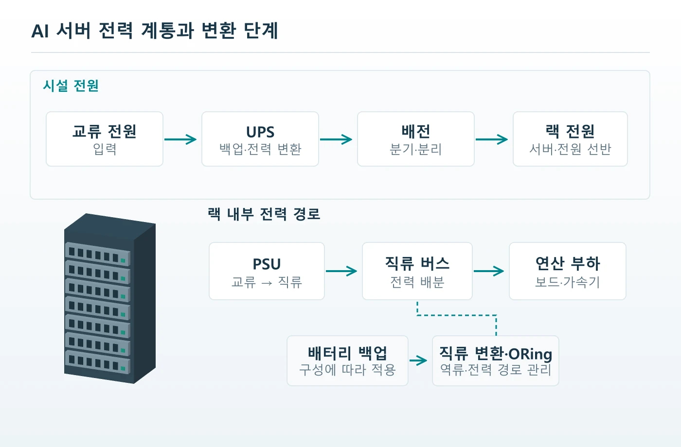
02기동 시퀀스와 백업 전환
돌입전류와 우회 시퀀스
전원이 처음 인가될 때 커패시터 전압은 입력 측 전압보다 낮을 수 있습니다. 이 전압 차가 배선과 정류 경로의 작은 임피던스에 걸리면 짧은 시간 큰 충전 전류가 흐를 수 있습니다. 기동 제한 회로는 이 초기 에너지 유입을 관리하며, 정상 운전 손실을 줄이기 위해 제한 소자를 나중에 우회하는 구성이 사용됩니다.
충전 시작, 충전 상태 확인, 우회 접점 투입, 정상 부하 허용은 관련되어 있지만 같은 사건은 아닙니다. 어떤 설계는 전압을 감시하고 다른 설계는 제어 상태와 시간을 함께 사용하므로, 임의의 지연 시간 하나를 모든 전원장치에 적용할 수 없습니다. 실제 시퀀스는 입력 전압 범위, 커패시터와 제한 소자, 재기동 조건에 맞춰 검증해야 합니다.
접점 투입 시점
입력과 커패시터 사이의 전압 차가 충분히 줄기 전에 저항을 우회하면, 낮아진 경로 임피던스로 큰 충전 과도가 흐를 수 있습니다. 반대로 우회가 이루어지지 않으면 제한 소자가 정상 부하 전류를 오래 받아 과열될 수 있습니다. 접점에는 닫히는 능력뿐 아니라 제어 명령에 맞게 확실히 닫혔는지 판단할 수 있는 회로적 검증이 필요합니다.
단순한 저항·커패시터 직류 회로에서는 충전 속도를 R과 C의 관계로 설명할 수 있습니다. 그러나 교류 입력, 정류기, PFC 제어와 이미 연결된 부하가 포함된 PSU의 실제 파형을 이 단순식 하나로 보증할 수는 없습니다. 초기 계산은 부품 에너지와 순서 검토에 사용하고, 투입 전류와 접점 전압은 실회로 파형으로 확인합니다.
짧은 정전과 재기동
정상 기동이 성공해도 짧은 정전 직후의 재기동은 다른 조건이 될 수 있습니다. 커패시터에 전하가 남거나 제한 소자의 온도가 높을 수 있고, 코일 전압 저하로 접점이 해제되는 시점도 제어 보드의 복구 시점과 다를 수 있습니다. 반복 전원 인가 시험에는 충분히 식은 기동뿐 아니라 부분 방전과 고온 재기동을 포함해야 합니다.
| 상태 | 주요 전류 경로 | 검증 포인트 |
|---|---|---|
| 기동 충전 | 제한 소자를 거치는 경로 | 피크 전류·에너지·온도 |
| 우회 투입 | 접점으로 전류 이전 | 투입 시점·잔류 전압·바운스 |
| 정상 운전 | 닫힌 접점을 포함한 저저항 경로 | 전압 강하·온도 상승·코일 유지 |
| 복구·재기동 | 잔류 전하와 제어 상태에 따라 변화 | 해제·재투입 순서와 반복성 |
우회 접점의 고장 영향
우회 접점이 붙은 채 남으면 다음 기동에서 제한 기능이 의도대로 동작하지 않을 수 있습니다. 접점이 닫히지 않는 고장은 제한 소자에 부담을 남기며, 흔들리는 코일 구동은 반복 접촉과 발열을 만들 수 있습니다. 고장 분석에서는 접점 단품의 외관과 함께 명령 신호·코일 전압·제한 소자 양단 전압을 시간축에 맞춰 대조합니다.
전원을 끄는 과정에서도 부하 전류와 접점 해제 순서를 구분합니다. 부하가 이미 줄어든 뒤 해제하는 설계와 전류가 남은 상태에서 해제되는 고장 상황은 다른 차단 부담을 줍니다. 정상 운전만으로 개폐 정격을 판단하지 않고, 저전압·제어 전원 상실·보호 동작에서 접점이 어떤 전류를 끊는지도 시험 계획에 반영합니다.
UPS와 배터리 백업의 전환
시설 UPS와 랙 배터리 백업은 모두 전원 연속성을 돕지만 같은 방식으로 부하를 공급하지는 않습니다. 온라인 이중변환 UPS는 정상 상태에서도 정류·직류 링크·인버터를 통해 부하를 공급하는 구성이며, 랙 BBU는 설계된 직류 버스에 에너지를 보탤 수 있습니다. 따라서 정전 순간마다 기계식 접점 하나가 서버 전원을 갈아탄다는 설명으로 모든 구조를 묶을 수 없습니다.
이중변환 UPS에서 상용 전원이 사라져도 인버터는 배터리 측 에너지를 이용해 출력을 이어 갈 수 있습니다. 정상 운전에서 배터리 운전으로 넘어가는 이 동작과, 인버터 경로를 벗어나 바이패스로 넘기는 동작은 구분해야 합니다. 접점이 필요한 위치와 전환 시간이 무엇을 뜻하는지는 UPS의 실제 토폴로지에서 확인합니다.
정적 바이패스와 정비 바이패스
정적 바이패스는 반도체 소자를 사용해 부하를 바이패스 전원 경로로 전환하는 기능입니다. 정비 바이패스는 장비를 점검하거나 교체할 때 부하 경로를 구성하는 기계식 스위치·차단기 등의 조합으로 구현될 수 있습니다. 전환 조건, 동기 상태와 인터록을 함께 다뤄야 하므로 두 경로를 하나의 릴레이 동작으로 그리지 않습니다. 정비 바이패스 경로 자체가 에너지를 저장하지는 않으므로, 그 공급원이 끊겼을 때 백업을 보장하는 기능은 아닙니다.
기계식 스위치가 열려 있다는 사실만으로 정비 가능한 안전 상태가 확정되지는 않습니다. 다른 공급원, 역급전, 에너지 저장부와 관련 차단 장치를 함께 고려해야 하며 요구되는 단로·절연 기능은 제품과 시스템 기준에 따라 확인합니다. 접점 부품의 간격만 측정해서 UPS 전체의 안전 분리를 보증할 수는 없습니다.
랙 DC 버스와 ORing
공개 OCP Open Rack V3 배터리 백업 자료는 랙 직류 버스와 배터리 변환부의 연결을 보여줍니다. 여러 전원 사이의 역류를 막고 공급을 이어 가는 기능에는 ORing과 전력반도체 제어가 사용될 수 있습니다. 이 자료를 근거로 모든 BBU에 기계식 접촉기가 들어간다거나, 접촉기가 가장 빠른 보호를 전담한다고 말할 수는 없습니다.
| 전력 기능 | 대표 구현 | 접점 검토의 초점 |
|---|---|---|
| 고속 전력변환 | PFC·인버터·DC/DC 반도체 | 기계식 개폐와 기능 분리 |
| 정적 전원 전환 | 반도체 기반 정적 스위치 | 전환 조건·고장 시 경로 |
| 기계식 연결·차단 | 적합한 릴레이·접촉기·스위치 | 통전·개폐·절연 요구 |
| 랙 백업·역류 방지 | BBU 변환부·ORing 등 | 버스 전압·역방향 조건·보호 협조 |
중복 전원과 공통 원인
전원 모듈을 두 개 사용해도 두 경로가 같은 환경과 조립 문제를 공유하면 동시에 영향을 받을 수 있습니다. 부품의 온도 조건, 구동 전원, 접합 공정이나 오염 원인이 공통인지 살펴봐야 합니다. 중복 구성을 평가할 때는 모듈 수뿐 아니라 하나의 고장이 다른 경로로 퍼지는 방식과 감시 범위도 확인합니다.
결국 AI 서버 전기접점의 선정 단위는 데이터센터라는 이름이 아니라 구체적인 전력 기능입니다. 기동 우회, 정상 통전, 부하 개폐와 정비 경로는 서로 다른 시험 조건을 요구합니다. 같은 접점 재료를 사용하더라도 시스템에서의 역할이 바뀌면 승인 근거를 다시 검토해야 합니다.
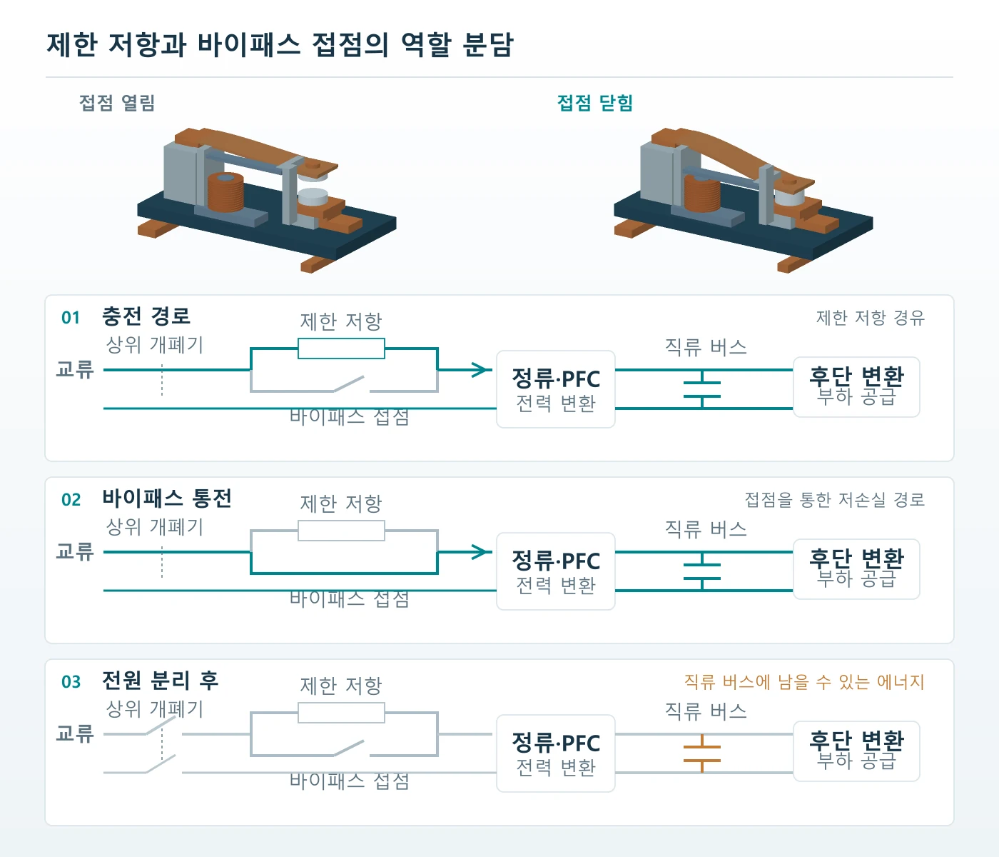
03접촉저항·발열과 개폐 손상
접촉저항과 열의 이동
접점이 닫혀 있어도 전류가 저항 없이 흐르는 것은 아닙니다. 두 면의 미세한 돌기가 실제로 닿는 접촉 영역에서 전류가 좁아지고, 표면막과 접합부, 캐리어 자체에도 저항이 존재합니다. 전원 경로의 발열을 분석할 때는 눈에 보이는 접점 머리만이 아니라 전류가 지나가는 전체 연결부를 나누어 봅니다.
겉보기 접촉면적과 실제 전류가 통하는 면적은 다릅니다. 접촉력과 표면 형상, 재료의 변형 특성에 따라 미세 접촉점의 수와 크기가 달라집니다. 접점 머리의 외경을 키우는 것만으로 저항이 비례해서 낮아진다고 볼 수 없으며, 필요한 힘이 실제 조립 상태에서 전달되는지도 확인해야 합니다.
전력 손실의 비교
저항성 손실은 직류 또는 해당 구간의 실효전류를 사용해 P = I²R로 비교할 수 있습니다. 설명을 위해 두 측정 단자 사이의 전체 경로에 40 A가 흐르고 저항이 0.5 mΩ라고 가정하면 손실은 0.8 W입니다. 같은 전류에서 저항이 2 mΩ가 되면 3.2 W가 되며, 이 값들은 특정 제품의 사양이나 합격 기준이 아닌 가상 계산 예입니다.
이 계산의 R에 접점 한 쌍만 포함하는지, 캐리어와 리벳 접합부까지 포함하는지 먼저 정해야 합니다. 전류가 두 배가 되면 같은 저항에서 손실은 네 배가 되지만, 실제 운전에서는 저항과 접촉 상태도 온도에 따라 달라질 수 있습니다. 와트 단위의 손실만으로 접점 온도를 결정할 수 없으므로 방열 경로와 운전 시간을 함께 검토합니다.
캐리어와 단자의 역할
전류와 열은 접점재에서 캐리어, 단자와 외부 도체로 이어집니다. 캐리어의 좁은 목 부분, 리벳 접합면의 불완전한 밀착, 단자 연결부의 저항은 접촉면 외부에서 온도를 올릴 수 있습니다. 열화상에서 밝게 보이는 위치만 보고 접점 소재를 바꾸기보다, 구간별 전압 강하와 온도를 함께 대조합니다.
| 경로 구간 | 저항 증가 요인 | 관찰 방법 |
|---|---|---|
| 접촉면 | 표면막·접촉력 변화·마모 | 정해진 힘에서 전압 강하와 표면 비교 |
| 리벳·용접 접합부 | 밀착 부족·계면 결함·균열 | 구간 저항·단면·접합 강도 |
| 캐리어 | 단면 부족·재료 상태·형상 | 치수·도전 특성·온도 분포 |
| 단자·외부 연결 | 체결·납땜·배선 상태 | 측정점 구분과 실제 장착 조건 |
주위 온도와 열적 여유
서버 전원장치에서는 공기 흐름과 주변 발열원이 접점 조립체의 시작 온도를 바꿉니다. 코일에서 발생한 열이 더해질 수 있고, 장시간 온도 상승은 스프링과 접합부의 상태에도 영향을 줍니다. 개방된 시험대의 낮은 온도 결과를 밀집된 실제 장착 상태에 그대로 적용하지 않도록 시험 배치와 냉각 조건을 기록합니다.
AI 서버 전기접점의 열 설계는 저항을 낮추는 일과 열을 내보내는 일을 함께 다룹니다. 저항이 안정적인지, 온도가 허용 범위 안에서 머무는지, 반복 운전 후에도 접촉력과 접합 상태가 유지되는지를 이어서 확인해야 합니다. 초기 저항 한 번의 측정으로 장기 통전 품질을 대표시키기 어렵습니다.
투입·차단과 접점 손상
통전 중에는 붙어 있던 접점이 개폐 순간에는 빠르게 변하는 접촉 영역을 거칩니다. 투입할 때 충돌 후 다시 떨어지는 바운스가 생길 수 있고, 차단할 때는 마지막 접촉점으로 전류가 집중됩니다. 이 짧은 과정의 전류·전압·속도가 장시간 정상 통전과는 다른 손상을 만들 수 있습니다.
바운스 동안 전류가 흐르면 반복적인 접촉과 아크가 국부 가열을 만들 수 있습니다. 용융된 영역이 다시 붙는 미세 용착이나 재료 이동이 누적되면 표면 형상과 이후 동작이 달라집니다. 바운스는 접점재만의 특성이 아니라 가동부 질량, 스프링, 구동력과 충돌 조건이 함께 만드는 조립체의 거동입니다.
교류와 직류의 차단 조건
교류는 주기적인 전류 영점이 있지만 직류에는 같은 자연 영점이 없습니다. 그렇다고 교류 접점이 언제나 쉽게 차단되거나 직류 접점은 재료만 바꾸면 된다는 뜻은 아닙니다. 전압, 전류, 부하의 인덕턴스, 접점 간격과 이동 속도, 아크 제어 구조를 포함한 제품의 검증 조건을 확인해야 합니다.
고전압 직류 배전을 검토하는 AI 전력 구조도 등장하고 있어 기존 저전압 버스의 경험을 그대로 옮기기 어렵습니다. 전압 영역이 바뀌면 열린 접점의 전기적 스트레스와 절연 요구, 차단 시 아크 조건이 함께 달라집니다. 신구 구조가 공존하는 단계일수록 서버용이라는 용도명보다 실제 배전 전압과 보호 구성을 명시해야 합니다.
접촉력과 구동 회로
접촉력은 닫힌 상태의 저항과 안정성에 영향을 주지만, 힘을 높이는 것만으로 모든 문제가 해결되지는 않습니다. 구동부의 여유, 스프링 응력과 충돌 에너지도 함께 달라질 수 있습니다. 특히 리벳 높이와 캐리어 휨이 바뀌면 동일한 액추에이터 이동량에서도 접촉 시점과 최종 힘이 달라집니다.
| 조건 | 접점에 나타날 수 있는 현상 | 확인할 입력 |
|---|---|---|
| 큰 투입 과도 | 국부 가열·용착·표면 변화 | 투입 전압·전류 파형과 충전 상태 |
| 바운스 | 반복 접촉·아크·접촉 지연 | 구동 파형·가동부·스프링 조건 |
| 부하 차단 | 아크 침식·재료 전이 | AC/DC·부하 종류·해제 순서 |
| 코일 구동 변화 | 미동작·채터·해제 지연 | 코일 온도·전압·억제 회로 |
해제와 보호의 협조
코일의 서지 억제 회로는 제어 소자를 보호하지만 선택한 방식에 따라 코일 전류의 감소와 접점 해제 시간이 달라질 수 있습니다. 따라서 억제 부품을 변경한 뒤에는 전기적 잡음만이 아니라 실제 해제 파형도 비교합니다. 저전압에서의 불완전 흡인이나 반복 채터가 있으면 접점 손상이 제어 전원 문제에서 시작되었을 가능성도 살펴야 합니다.
단락처럼 매우 큰 전류가 흐르는 상황에서는 전자기적 힘과 급격한 발열도 접점 안정성에 영향을 줍니다. 일반 릴레이가 해당 고장 전류를 직접 차단하도록 검증되었다고 가정해서는 안 됩니다. 퓨즈나 차단기 등 보호장치와의 협조 조건을 정의하고, 정상 개폐 수명과 별도로 고장 조건의 견딤·차단 책임을 배분합니다.
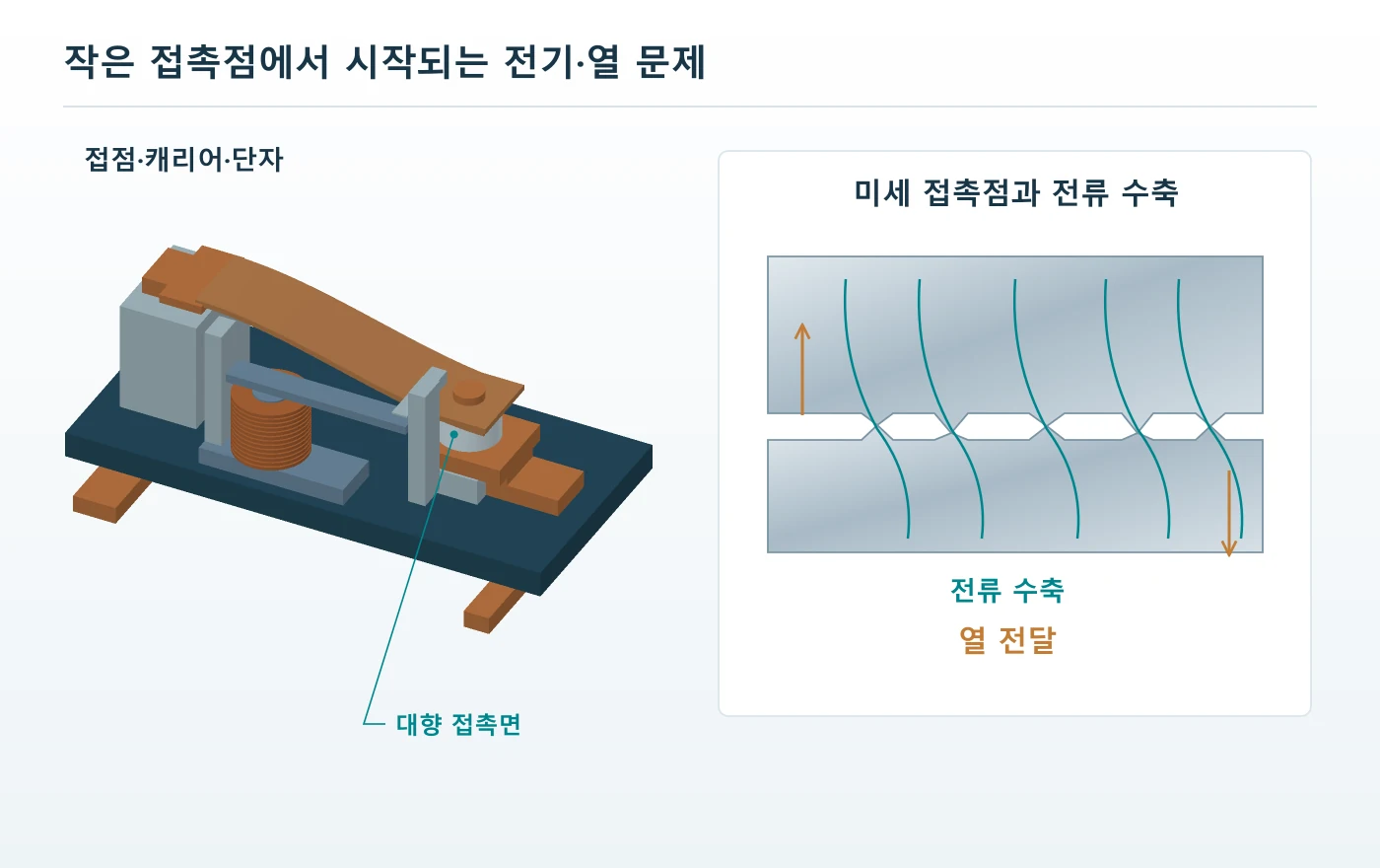
04접점재·형상과 제조 공정
접점재와 접촉 형상
접점재는 전류를 잘 흘리는 성질과 개폐 손상을 견디는 성질을 함께 요구받습니다. 높은 도전성만 보고 순수 금속을 선택하거나, 내아크성이 좋은 조성 하나를 모든 회로에 적용할 수는 없습니다. 정상 통전 시간과 투입·차단 파형, 필요한 수명과 접촉력을 먼저 정하고 재료의 장단점을 비교합니다.
은계 접점에는 AgNi, AgSnO₂ 등 서로 다른 계열이 사용되며, 조성과 조직은 용착·침식·저항 거동에 영향을 줍니다. 같은 계열명 안에서도 제조 방식과 미세조직, 후속 가공 상태가 다를 수 있습니다. 따라서 재료명만 동일하다는 이유로 승인된 접점과 교환 가능하다고 판단하지 않고 실제 부하 시험과 공급 사양을 대조합니다.
전력용과 미소전류용
전력 접점과 미소전류 신호 접점은 해결해야 할 문제가 다릅니다. 큰 개폐 에너지를 다루는 접점의 재료 선택을 낮은 전압·전류에서 표면막의 영향을 받는 신호 회로에 그대로 적용할 수 없습니다. 미소전류 전기접점의 설계와 검사처럼 사용 전압과 전류, 표면 상태를 함께 구분해야 합니다.
도금 역시 은색 또는 금색이라는 외관으로 기능을 판단할 수 없습니다. 금속 종류, 바탕층, 두께와 균일성, 접촉 운동과 개폐 에너지에 따라 적합성이 달라집니다. 얇은 표면층을 가진 부품을 벌크 접점재와 같은 수명으로 간주하지 않고, 마모나 아크 후에 어떤 층이 노출되는지까지 검토합니다.
머리·곡률·위치 관계
접촉면의 곡률은 접촉 위치와 국부 압력, 정렬 오차에 대한 민감도에 영향을 줍니다. 평평한 두 면은 기울어지면 가장자리부터 닿을 수 있고, 곡면은 힘과 재료 변형에 따라 접촉 영역이 형성됩니다. 어느 형상이 무조건 우수한지보다 상대 접점과의 조합, 조립 편차와 가동 궤적을 함께 평가합니다.
| 설계 요소 | 연결되는 기능 | 함께 검토할 조건 |
|---|---|---|
| 접점재 조성·조직 | 저항·용착·침식의 균형 | 실제 개폐 파형과 접촉력 |
| 접촉면 곡률·높이 | 첫 접촉 위치와 힘 분포 | 상대 접점·기울기·오버트래블 |
| 접점층과 받침 재료 | 전기 기능과 접합성의 분담 | 계면·노출층·사용 방향 |
| 표면 상태 | 접촉 안정성과 마모 | 오염·피막·취급·보관 |
귀금속 배치와 접합성
복합 리벳이나 접점 테이프는 필요한 위치에 접점재를 두고 다른 부분은 접합과 지지에 맞춘 재료로 구성할 수 있습니다. 귀금속 사용량을 줄이는 목적과 함께 접합성·성형성·열 전달을 맞추는 설계가 필요합니다. 접점층이 필요한 작업면에 남아 있는지, 성형과 접합 뒤 계면이 건전한지를 확인해야 비용과 기능을 함께 관리할 수 있습니다.
재료 검토의 최종 단위는 단품 시편이 아니라 조립된 접점 쌍과 그 구동 조건입니다. 소재 시편의 물성은 후보를 좁히는 데 유용하지만 바운스, 전류 경로와 접합 상태까지 대표하지는 않습니다. 공급 소재와 완성 조립체 시험을 연결해야 부품 변경의 영향을 실제 회로에서 해석할 수 있습니다.
리벳·캐리어의 제조 공정
접점 조립체는 접점재를 만드는 공정, 전류를 전달하는 캐리어를 만드는 공정, 둘을 연결하는 공정으로 나누어 볼 수 있습니다. 각 부품이 도면 치수에 맞아도 결합 후 높이와 기울기, 전기저항이 달라지면 기능은 달라집니다. 제조 검토는 접점 단품과 캐리어 단품의 합격에서 끝나지 않고 최종 조립 상태까지 이어져야 합니다.
캐리어는 전류를 전달하면서 접점을 지지하며, 설계에 따라 스프링 기능도 맡습니다. 프레스 전단과 굽힘은 홀 위치, 버 방향, 평탄도와 가공경화 상태를 바꿀 수 있습니다. 도전성과 탄성을 모두 요구하는 부품에서는 재료의 공급 상태와 후속 열 이력을 함께 관리해야 단면을 키우는 것만으로 해결되지 않는 문제를 다룰 수 있습니다.
리벳 체결과 지지 방식
리벳 접점을 체결할 때는 축을 변형시키는 힘이 접점 머리와 캐리어에 전달됩니다. 지지 위치가 맞지 않거나 성형량이 과하면 머리 기울기, 작업면 변형과 캐리어 휨이 생길 수 있습니다. 접점 표면을 단순히 단단한 면에 대고 누르는 방식보다 기능면을 보호하면서 필요한 체결 변형을 만드는 지그 설계가 중요합니다.
체결이 약하면 접합면의 밀착과 유지력이 불안정해지고, 과도한 체결은 균열이나 기능면 손상을 만들 수 있습니다. 따라서 성형 높이 한 항목만 관리하기보다 힘·변위 기록, 최종 형상, 접합 강도와 구간 저항을 연결합니다. 공정 신호가 정상 범위라는 사실도 실제 조립 품질과의 상관관계가 확인되어야 의미가 있습니다.
용접·브레이징·접점 스트립
접점 부착에는 리벳팅 외에도 저항 용접, 브레이징, 접점재가 부착된 스트립의 성형 등 여러 경로가 있습니다. 용접에서는 받침 재료와 돌기 형상, 전극 상태가 접합에 영향을 주고, 열을 이용하는 공정은 캐리어의 조직과 스프링 특성에도 영향을 줄 수 있습니다. 형상·재료·생산량과 요구 검사에 맞춰 공정을 비교해야 합니다.
| 공정 | 중요 관리점 | 완성품 확인 |
|---|---|---|
| 프레스 가공 | 소재 상태·홀·버·굽힘 기준 | 위치·평탄도·균열·스프링 거동 |
| 리벳팅 | 지지·성형량·힘과 변위 | 머리 자세·유지력·접합부 저항 |
| 용접·브레이징 | 접합 재료·에너지·전극·열 이력 | 계면·강도·변형·도전 경로 |
| 세척·포장 | 잔류물·건조·취급·재오염 | 기능면 상태와 로트 추적 |
청정도와 공정 이력
프레스유, 연마 잔류물과 취급 오염은 접촉면이나 접합면으로 이동할 수 있습니다. 세척은 외관을 밝게 만드는 작업이 아니라 해당 재료와 기능에 맞는 잔류물 관리이며, 접점 표면에 불필요한 연마나 피막 변화를 만들지 않아야 합니다. 정밀부품 세척과 청정도를 기준으로 세척 뒤 보관·포장까지 연결합니다.
소재 로트, 금형 개정, 접합 조건과 검사 결과가 연결되어야 이상이 발견되었을 때 범위를 좁힐 수 있습니다. 변경된 윤활제나 세척제, 전극 교체와 같은 공정 변화도 전기적 성능에 영향을 줄 가능성이 있습니다. 완성품의 외관만 보관하기보다 부품과 공정 이력을 같은 식별 체계로 묶는 것이 재현성과 원인 분석에 유리합니다.
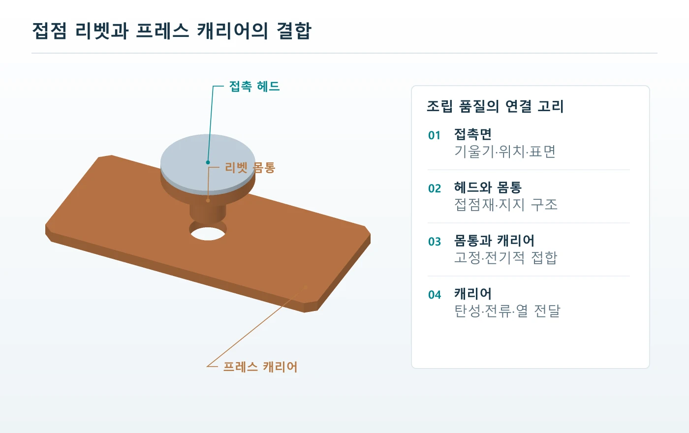
05부품 검사와 실부하 검증
치수·저항·접합 검사
접점 검사에서는 무엇을 측정하는지와 어떤 상태에서 측정하는지를 함께 정의해야 합니다. 리벳 머리 높이만 맞아도 상대 접점에 닿는 위치가 어긋날 수 있고, 무부하 외관이 정상이더라도 필요한 접촉력에서 저항이 불안정할 수 있습니다. 치수·기계·전기 검사를 같은 조립 기준으로 연결해야 누락된 기능을 찾을 수 있습니다.
치수 검사는 작업면 높이와 곡률, 축 또는 머리의 기울기, 캐리어 기준면과 홀 위치를 기능에 맞춰 선택합니다. 조립 후에는 접점이 처음 닿는 위치와 이후 추가 이동량을 확인하고, 구동 범위에서 필요한 힘이 나오는지 평가합니다. 측정 지그가 캐리어를 실제보다 강하게 구속하면 변형과 위치 편차가 가려질 수 있습니다.
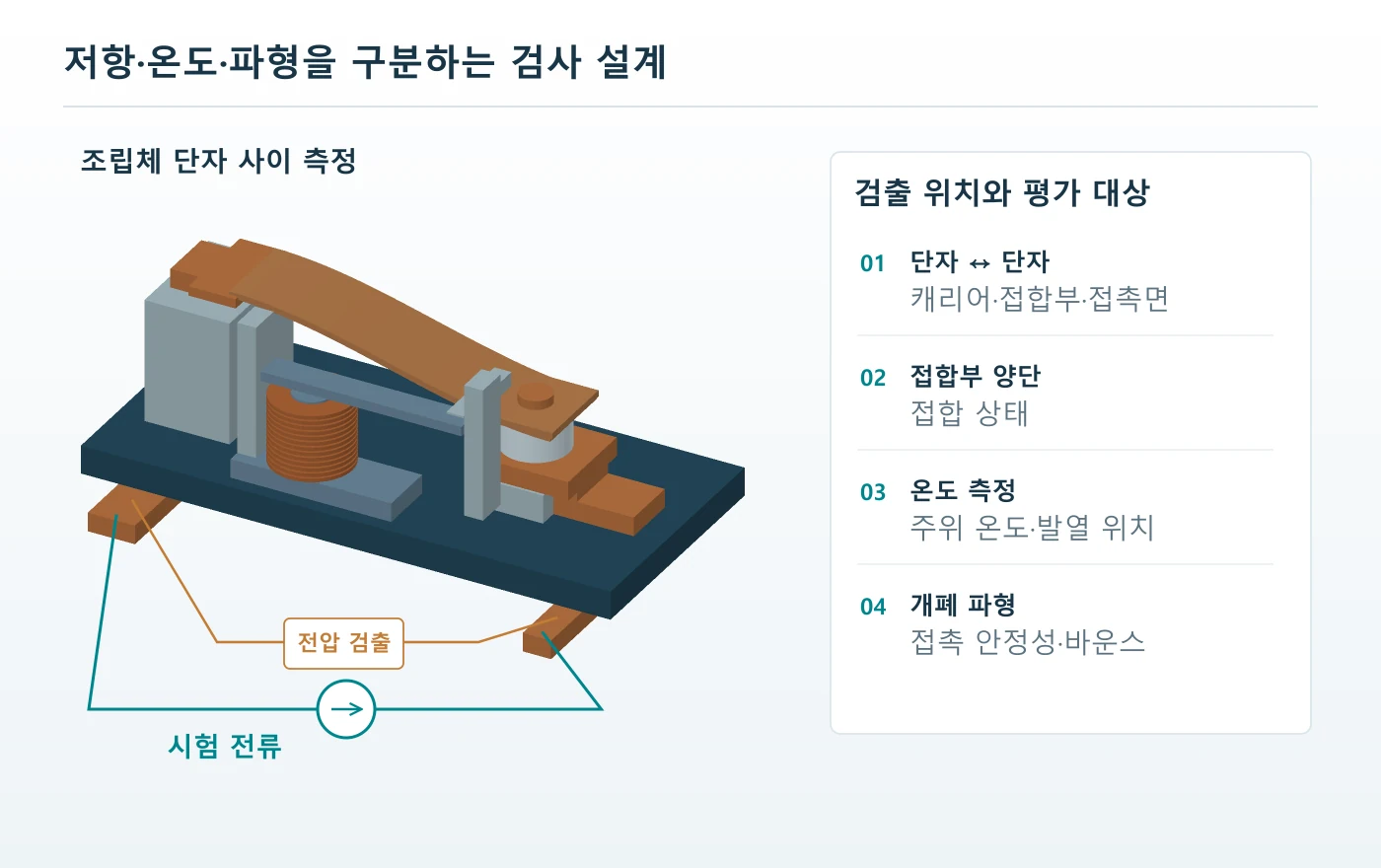
4선식 저항 측정
낮은 저항을 측정할 때는 전류를 공급하는 선과 전압을 감지하는 선을 분리하는 4선식 구성이 유용합니다. 하지만 감지점을 어디에 두는지에 따라 접촉면만 볼 수도 있고 리벳·캐리어·단자 저항까지 포함할 수도 있습니다. 측정 전류, 접촉력, 유지 시간과 온도를 기록해야 다른 로트나 내구 시험 전후의 값을 비교할 수 있습니다.
전력 접점의 통전 검증과 표면막에 민감한 저전력 저항 검사는 목적이 다릅니다. 큰 시험 전류는 온도를 올리고 표면 상태를 바꿀 수 있으므로, 이후의 낮은 전류 측정이 원래 상태를 그대로 나타낸다고 보기 어렵습니다. 필요한 시험 순서와 전기적 전처리를 지정하고 초기 상태와 부하 이력 이후 상태를 구분해 기록합니다.
접합부의 별도 평가
접합부의 기계적 유지력과 전기적 건전성은 서로 관련되지만 같은 측정값이 아닙니다. 리벳이 빠지지 않아도 접합면 저항이 높을 수 있고, 초기 저항이 낮아도 반복 열 이력 뒤 균열이나 이완이 생길 수 있습니다. 인장·전단·비틀림 중 기능에 맞는 시험과 단면 관찰, 구간 저항을 조합해 판단합니다.
| 검사 | 고정할 조건 | 얻을 수 있는 정보 |
|---|---|---|
| 치수·자세 | 기준면·고정력·측정 방향 | 접촉 위치와 조립 편차 |
| 접촉력·변위 | 구동 위치·속도·지그 강성 | 첫 접촉과 힘 형성 |
| 4선식 저항 | 전류·감지점·힘·온도 | 정의된 구간의 전기저항 |
| 접합 강도·단면 | 하중 방향·절단 위치·시료 이력 | 유지력과 계면 건전성 |
| 온도 상승 | 장착·배선·공기 흐름·통전 시간 | 실제 열 경로의 성능 |
반복성과 판정 기준
측정값이 허용차 경계에 가까우면 지그 재장착, 탐침 접촉과 온도 변화가 판정을 바꿀 수 있습니다. 작업자와 장비가 달라도 같은 결론을 내릴 수 있는지 반복 측정으로 확인하고, 측정 불확도와 분해능을 요구 수준에 맞춰 검토합니다. 표시 자릿수가 많다는 이유만으로 실제 판정 능력이 높아지는 것은 아닙니다.
전수 검사와 표본 검사는 검출하려는 결함과 시험의 파괴 여부에 따라 나눕니다. 빠른 외관·위치 검사와 정기적인 단면·내구 시험은 서로 다른 역할을 하며, 모든 항목을 전수 검사한다는 말이 검증의 충분성을 보증하지는 않습니다. 검사 빈도는 공정의 안정성, 결함 영향과 변경 이력에 근거해 정합니다.
실부하 검증과 시험 행렬
전기접점의 승인에는 정상 통전 시험과 실제 개폐 시험이 모두 필요할 수 있습니다. 통전은 저항과 열적 여유를 보여주고, 개폐는 투입 과도·바운스·아크에 대한 반응을 보여줍니다. 전류가 같은 시험이라도 부하 파형과 개폐 순서가 다르면 접점이 받는 부담은 달라지므로 시험 목적을 먼저 나눕니다.
기계적 수명은 전기적 부하 없이 구동했을 때의 운동 내구를 나타낼 수 있습니다. 전기적 수명은 지정한 부하를 개폐하면서 평가하므로 같은 횟수로 직접 비교할 수 없습니다. 데이터시트의 긴 기계적 수명 수치를 가져와 서버 전원 회로의 실제 부하 수명으로 표시하지 않아야 합니다.
기동과 복구의 조합
기동 우회 접점은 정상 전압에서의 첫 기동뿐 아니라 입력 전압의 상한·하한, 고온 재기동과 짧은 전원 중단을 검토합니다. 커패시터 상태와 제한 소자 온도를 바꿔 가며 투입 파형이 달라지는지 살펴봅니다. 제어 전원 저하가 접점 해제를 유발하는 상황도 포함해야 실제 현장에서 생길 수 있는 순서를 놓치지 않습니다.
정상 통전 시험에서는 실제 장착 방향, 단자 연결과 냉각 조건을 재현하는 것이 중요합니다. 전기적 내구 시험에서는 투입 전압·전류, 차단 부하와 주기, 코일 구동을 함께 기록합니다. 시료가 이미 다른 시험을 거쳤다면 그 이력이 결과를 바꿀 수 있으므로 시험 순서와 시료 배분도 계획해야 합니다.
시험 행렬과 불합격 정의
시험 전에 불합격을 정의하지 않으면 접점이 움직이기만 하면 통과했다는 모호한 결론에 이르기 쉽습니다. 용착과 미동작 외에도 저항 증가, 과도한 온도, 해제 지연, 절연 성능 저하와 접합 균열을 용도에 맞춰 평가합니다. 수치 한계는 제품 요구와 적용 기준에서 정하며 모든 접점에 공통인 임의 기준을 만들지 않습니다.
| 시험 축 | 대표 조건 | 평가 결과 |
|---|---|---|
| 기동 | 입력 범위·충전 상태·고온 재기동 | 돌입 파형·우회 완료·제한 소자 부담 |
| 정상 통전 | 전류·주위 온도·장착·냉각 | 전압 강하·온도 상승·힘 유지 |
| 개폐 내구 | 실부하·주기·구동 조건 | 용착·침식·저항·작동 시간 |
| 환경 노출 | 요구 온습도·부식성 환경·보관 | 표면·절연·접촉 안정성 |
| 기계 환경 | 요구 진동·충격·장착 조건 | 이탈·간헐 접촉·접합 손상 |
| 고장·보호 협조 | 보호장치와 고장 시나리오 | 책임 범위 내 견딤과 차단 결과 |
승인 시험과 양산 관리
설계 승인 시험은 선택한 구조가 요구 조건을 만족하는지 확인하고, 양산 검사는 승인된 상태가 반복되는지 감시합니다. 양산에서 모든 내구 시험을 재현할 수는 없으므로 소재·공정·치수·저항 등의 관리 항목을 승인 결과와 연결합니다. 변경이 생겼을 때 어느 시험을 다시 해야 하는지도 미리 정해 두어야 합니다.
소재 공급원, 접점 조성, 캐리어 열처리, 리벳 지그나 코일 억제 회로의 변경은 서로 다른 재검증 범위를 가질 수 있습니다. 변경 전후 외관이 같아도 전기적 파형과 접촉력은 달라질 수 있습니다. 시험 성적서에는 합격 여부와 함께 시료 구성·회로·환경·측정 위치를 남겨 이후 변경을 판단할 근거로 사용합니다.
06고장 진단과 제작 의뢰
고장 징후와 원인 분리
접점이 뜨겁다는 현상만으로 원인을 하나로 정할 수는 없습니다. 접촉력 저하, 표면막, 접합부 저항과 주변 열원이 비슷한 온도 상승을 만들 수 있습니다. 먼저 어느 구간에서 전압 강하가 커지는지 찾고, 같은 시점의 전류와 코일 상태를 비교해야 접점 표면 문제와 다른 경로 문제를 나눌 수 있습니다.
용착은 큰 전류만의 결과로 단정하기 어렵습니다. 충전이 끝나기 전 우회 투입, 바운스 중 반복 아크, 불안정한 코일 구동과 부적절한 부하 조건이 함께 작용할 수 있습니다. 손상된 접점을 교체하기 전에 투입 직전의 전압과 전류 파형, 제어 명령과 실제 움직임의 관계를 확보하는 것이 중요합니다.
전기 원인과 기계 원인
코일 명령이 정상이어도 단자 전압은 배선 강하나 구동 회로 때문에 달라질 수 있습니다. 반대로 코일 전압이 정상인데 동작이 늦으면 기계적 마찰, 스프링 상태와 접점 용착 흔적을 살펴야 합니다. 명령 신호, 실제 코일 전압, 접점 양단 전압과 전류를 분리해 기록하면 원인 후보를 줄이기 쉽습니다.
간헐적인 저항 증가는 측정 지그의 흔들림에서도 생길 수 있습니다. 먼저 감지점과 접촉력, 탐침 연결이 안정적인지 확인한 뒤 제품의 바운스나 접합 이완을 판단합니다. 불량 분석용 시료를 분해하거나 세척하면 원래 오염과 맞물림 상태를 잃을 수 있으므로 초기 관찰을 먼저 남기는 것이 유리합니다.
증상별 확인 순서
외관에서 보이는 변색, 파임과 돌기는 원인 판단의 단서입니다. 그러나 색상만으로 재료 조성을 판정하거나 한 장의 사진으로 아크의 방향과 전체 고장 이력을 확정하기는 어렵습니다. 손상 위치를 상대 접점과 맞춰 보고, 전기 파형·치수·단면 결과를 결합해야 설명의 신뢰도가 높아집니다.
| 징후 | 우선 분리할 원인 | 다음 확인 |
|---|---|---|
| 국부 발열 | 접촉면·접합부·단자·주변 열 | 구간 전압 강하와 온도 |
| 용착·분리 불량 | 투입 과도·바운스·해제 조건 | 파형·코일 구동·표면 손상 |
| 채터·간헐 접촉 | 구동 전압·기계 거동·측정 지그 | 동시 신호와 반복 재현 |
| 우회 실패 | 명령·코일·접점·연결 경로 | 제한 소자 전압과 온도 |
| 내구 후 저항 증가 | 힘 저하·침식·표면막·접합 변화 | 초기 대비 힘·단면·저항 분포 |
부품 변경보다 먼저 할 일
원인이 확인되지 않은 상태에서 접점재만 바꾸면 초기 증상은 줄어도 다른 손상이 생길 수 있습니다. 예를 들어 용착 저항을 높이는 선택이 접촉저항이나 조립 조건에 새로운 요구를 만들 수 있습니다. 변경 가설을 먼저 정하고 같은 부하·구동 조건에서 비교해야 개선 효과와 부작용을 분리할 수 있습니다.
고장품 한 개의 관찰과 전체 로트의 문제 범위도 구분합니다. 같은 소재·공정·사용 조건의 이력을 대조해 공통 원인이 있는지 살펴보고, 재현 시험으로 관련성을 확인합니다. 시료 하나에서 발견한 표면 흔적을 모든 AI 서버 전기접점의 일반적인 수명 한계로 확대하지 않아야 합니다.
제작 도면과 의뢰 조건
전기접점 제작 검토는 형상 도면과 사용 회로가 만나는 지점에서 시작합니다. 부품 외경과 높이, 소재명만 전달하면 제조 가능한 모양은 검토할 수 있어도 접촉 기능의 적합성까지 판단하기 어렵습니다. 기동 우회용인지 부하 개폐용인지, 어느 전압 영역에서 쓰이는지와 상대 부품을 함께 제시해야 합니다.
회로 조건에는 정상 전류뿐 아니라 투입 피크와 지속 시간, 차단 부하, 개폐 주기와 예상 사용 이력을 포함합니다. 코일이나 액추에이터 정보가 있는 경우 접촉력과 변위 범위, 허용 동작 시간도 연결합니다. 아직 확정되지 않은 조건은 추정값과 검증 필요 항목으로 나누어야 임시 가정이 승인 사양처럼 굳어지는 일을 피할 수 있습니다.
기능면과 조립 기준
도면에는 작업면, 리벳 체결부와 측정 기준을 구분하고, 조립 후 필요한 높이·기울기·접촉 위치를 표시합니다. 캐리어의 자유 상태와 고정 상태 중 어느 상태에서 치수를 판정하는지도 중요합니다. 공차 누적과 조립 간극을 함께 검토하면 단품 허용차가 최종 접촉 위치에 미치는 영향을 정리할 수 있습니다.
표면 요구는 광택 정도보다 기능을 중심으로 작성합니다. 접촉면과 접합면의 허용 결함, 도금 또는 접점층의 적용 영역, 버와 모서리, 청정도와 보관 조건을 구분합니다. 검사에서 확인할 수 없는 모호한 표현보다 위치·범위·측정 방법이 연결된 요구가 공정 검토와 승인에 도움이 됩니다.
의뢰 자료의 구성
접점 단품을 의뢰하는지, 캐리어에 부착된 조립체까지 의뢰하는지에 따라 필요한 자료가 달라집니다. 후자의 경우 조립 기준과 접합 강도, 구간 저항과 최종 접촉력의 책임 범위를 함께 정합니다. 접점 제조업체와 릴레이·전원장치 설계자가 각각 어떤 검증을 담당하는지 분명해야 중간 단계의 합격을 시스템 승인으로 오해하지 않습니다.
| 자료 | 포함할 내용 | 검토 목적 |
|---|---|---|
| 회로·용도 | 위치·AC/DC·우회 또는 개폐 역할 | 실제 전기적 부담 정의 |
| 부하·시퀀스 | 정상 전류·투입 과도·차단·재기동 | 재료와 검증 조건 선정 |
| 부품·조립 도면 | 접촉면·기준·상대 부품·힘·변위 | 공차와 공정 설계 |
| 소재·표면 | 조성·공급 상태·접점층·피막 | 성형·접합·도전 기능 검토 |
| 검사·수량·변경 | 판정 기준·시료·예상 수량·개정 | 공정 투자와 승인 범위 결정 |
시제품과 반복 생산
시제품은 작동 원리와 공정 가능성을 확인하는 단계이며, 한 개가 동작했다고 반복 생산의 안정성이 입증되지는 않습니다. 생산 조건이 정해지면 주요 치수와 접합 신호, 저항과 기능 결과가 로트와 시간에 따라 어떻게 변하는지 확인합니다. 소재나 공정이 바뀔 때 다시 확인할 항목까지 정해 두면 개발과 양산의 연결이 명확해집니다.
AI 서버 전기접점은 맡겨진 전력 경로를 정해진 조건에서 안정적으로 연결하고 전환하는 역할을 합니다. 이를 위해 회로·접점재·캐리어·접합·구동·검사를 하나의 기능 요구로 연결해야 합니다. 제작 검토가 필요하다면 제품문의·개발의뢰에 부품도와 함께 적용 위치, 부하 조건과 필요한 공급 범위를 전달해 주세요.
English Edition · AI Server Power Contacts
AI server electrical contacts encounter different duties at energization and during sustained conduction. Charging a PSU capacitor requires control of inrush, while normal operation calls for reduced losses. Even where semiconductors perform fast power conversion, some designs use mechanical contacts to bypass a startup resistor or connect a defined power path.
The interactive 3D compares power disconnected → startup charging → resistor bypass → shutdown. The following illustrations and chapters distinguish PSU, UPS and rack-backup functions, then connect contact resistance and heating to materials, rivet and carrier manufacture, inspection and actual-load qualification.
One contact changes the current path
Explore the bypass contact during initial charging and normal conduction.
3D acceleration is unavailable. A static structural view is shown.
Drag or arrow keys to rotate · Home to reset
Power state
After the charging condition is met, the contact closes to bypass the limiting resistor.
Automatic playback is paused to respect reduced-motion preferences.
Functional circuit
Swipe horizontally to inspect the circuit.
Simplified PSU input resistor-bypass concept. Scene transitions do not represent control timing or switching waveforms. An open bypass contact leaves the resistor path connected.
Power paths and roles
Distinguish PSU startup bypass, UPS switching and rack battery backup by circuit.
From face to joint
Connect resistance and heat in contact faces, rivets and carriers to materials, geometry and actuation.
Manufacture and qualification
Relate drawings and processes to dimensional, joint and electrical checks and startup, carrying and switching tests.
01Server power paths and PSU circuits
Server power paths and the place of contacts
When an AI server is energized, its input power circuitry and capacitors prepare for operation before the GPUs begin their work. Charging an initially empty capacitor, entering steady operation and maintaining supply through a disturbance create different current conditions. Understanding AI server electrical contacts therefore starts with changes in the power path, rather than with the computing performance of the processors.
Semiconductor switches control current at high frequency for power conversion and fast protection. Depending on the circuit, mechanical contacts bypass a starting resistor, connect or disconnect a power path, or form part of a maintenance switching arrangement. The devices can coexist in one power system while operating on different time scales and serving different functions. Neither component category describes the entire system.
Server, rack and facility boundaries
A server PSU, a rack power shelf and a facility UPS are different design boundaries. Treating a small relay inside a PSU as equivalent to a power contactor in a UPS can lead to incorrect assumptions about voltage, current and interruption duty. Locate the component on the actual circuit first. Then separate its steady-state conditions from the conditions experienced during transitions.
| Location | Typical task | Conditions to distinguish |
|---|---|---|
| PSU input | Inrush limitation and bypass | Circuit topology, capacitor state and bypass timing |
| Rack DC path | Supply sharing, reverse-current blocking and backup | Electronic ORing versus mechanical switching |
| UPS power stage | Conversion, battery support and bypass | Static switching versus mechanical maintenance paths |
| Contact assembly | Contact, conduction and mechanical support | Contact material, carrier, joint and actuator force |
Rapid variation in an AI workload does not mean that a relay repeatedly follows every load change. Converter controls and energy-storage elements normally handle the fast response, while a startup bypass relay may remain closed throughout operation. Determine contact endurance requirements from actual switching commands, recovery events and fault scenarios. A processor-utilization trace is not a direct record of mechanical contact operations.
Conditions favoring mechanical switching
Mechanical contacts can provide a low-resistance closed path and a physical separation when open. Their operating delay, bounce, switching wear and coil-drive requirements must also be included in the design. Some high-temperature, high-density power designs implement the startup bypass with solid-state devices. The relevant question is which switching method suits the circuit, rather than whether every AI server must contain the same relay.
From the current path to manufacturing quality
Once the circuit function is defined, the important manufacturing characteristics become clearer. A path carrying substantial current for long periods depends on carrier cross-section and riveted-joint resistance as well as the mating contact faces. A contact that switches a live load also requires evaluation of bounce and arc damage. Diameters and heights on a drawing become useful when connected to these functional requirements.
The interactive 3D model compares a startup path through a resistor with a normal-operation path through a contact. Its geometry and current indicators explain functional relationships; they do not reproduce a particular server or constitute electrical or thermal simulation. The article uses that path to connect material selection, joining processes and test conditions to the work performed by the contact assembly.
Power-conversion circuits in a PSU
An AC-input PSU can transfer energy through input protection and filtering, rectification and power-factor correction, a DC link and an isolated DC/DC converter. The way these functions are combined differs between a diode-bridge architecture and alternatives such as totem-pole conversion. When reviewing contact placement, examine both the functional block diagram and the actual wired current path. Similar block names do not guarantee identical connections.
Power-factor correction controls the input-current waveform and the DC-link voltage. While its semiconductors switch repeatedly, a mechanical bypass contact may already be closed and carrying current continuously. The relay does not substitute for the high-frequency switching action of the PFC stage. Its mechanical operating speed is therefore not the regulation speed of the converter or the response time to every load transient.
Input and output voltage domains
The input, high-voltage DC link and low-voltage server output belong to different voltage domains. Public server power architectures include outputs such as 12 V or 48 V, but those values cannot simply be assigned to a relay in the input stage. Trace the two nodes actually connected by the contact. Determine both the conducting current and the voltage that can appear across the open gap.
The relay coil rating and contact rating are separate specifications. A control board can operate a coil at a low DC voltage while the contacts connect a higher-voltage AC or DC circuit. Confusing coil terminals with power terminals affects more than component selection. It can also lead to incorrect insulation-distance requirements, dielectric-test connections and assumptions about the stresses on the contact material.
Location of the startup bypass
In a resistor-bypass circuit, the limiting resistor and relay contact form parallel branches. The contact initially remains open so that charging current passes through the resistor. When the required conditions are met, closing the contact reduces the voltage and loss across the resistor. Opening this contact alone does not establish disconnection from the input supply, because the resistor branch remains electrically present.
| Item | What to verify | Misleading assumption |
|---|---|---|
| PFC switch | Conversion frequency, losses and control | A mechanical relay performs fast converter control |
| Bypass contact | Parallel branch across the limiter | An open bypass contact disconnects the input |
| Coil | Drive voltage, current, temperature and release | Coil voltage is the switched contact voltage |
| Contact circuit | Actual AC/DC voltage, current and transients | PSU output voltage applies to every contact |
Relating ratings to circuit conditions
A datasheet carrying-current rating, switching rating and maximum switching voltage do not mean the same thing. The permissible combination depends on load type, AC or DC operation, ambient temperature and required endurance. Do not combine independently listed maximum values into a new operating point. Review the stated load rating, test conditions and restrictions as one set before deciding that the proposed circuit is covered.
A drawing may contain enough geometry to manufacture an individual contact without explaining its circuit. Evaluating suitability requires more information. A resistor-bypass contact and a contact connecting a load directly can experience different transients even when their shapes are similar. Supplying the electrical role alongside the drawing allows material and assembly tolerances to be reviewed against the intended function.
02Startup sequences and backup transitions
Inrush current and the bypass sequence
At initial energization, capacitor voltage can be lower than the voltage presented by the input circuit. Applying that difference across a low-impedance wiring and rectifier path can produce a large charging current for a short interval. A startup limiter manages this initial energy transfer. Some designs subsequently bypass the limiting element to reduce the loss that would otherwise persist during normal operation.
Starting charge, confirming the charging state, closing the bypass and enabling normal load are related but distinct events. Some designs monitor voltage; others combine timing with controller state. One arbitrary delay cannot be applied to every PSU. The actual sequence must be validated against the input range, capacitance, limiting element and restart conditions, including cases where the capacitor is only partially discharged.
Contact closing time
Bypassing the resistor before the voltage difference between the input and capacitor has sufficiently decreased can produce a large charging transient through the lower-impedance path. If bypass never occurs, the limiter may overheat while carrying load for too long. Selection therefore involves more than the ability to close. The circuit must also establish whether the commanded transition has actually produced the intended operating state.
A simple DC resistor-capacitor network explains the basic dependence of charging time on resistance and capacitance. It does not reproduce every waveform in a PSU containing AC input, rectifiers, PFC control and connected loads. Use simplified calculations to review energy and sequencing, then verify closing current and contact voltage on the actual circuit. Keep the distinction between a screening model and a validated switching waveform.
Brief interruption and restart
A successful cold start does not establish correct behavior after a brief interruption. Residual capacitor charge, a hot limiting element and a relay release time that differs from controller recovery can change the sequence. Repeated power-application testing should therefore include partial discharge and hot restart as well as fully cooled startup. The relevant intervals must come from the intended operating scenario rather than convenience in the laboratory.
| State | Principal current path | Verification focus |
|---|---|---|
| Startup charge | Through the limiting element | Peak current, energy and temperature |
| Bypass closing | Current transfers to the contact | Timing, residual voltage and bounce |
| Normal operation | Low-resistance path including the closed contact | Voltage drop, temperature rise and coil hold |
| Recovery and restart | Depends on residual charge and control state | Release and reclosure sequence and repeatability |
Consequences of bypass faults
A bypass contact that remains welded closed can defeat the intended limitation on the next startup. Failure to close leaves the limiting element exposed, while unstable coil drive can produce repeated contact events and heating. Fault analysis should align the command signal, coil voltage and voltage across the limiter on the same time axis. The appearance of the removed contact is evidence, but it does not identify the sequence by itself.
Shutdown also requires attention to the order of load reduction and contact release. Releasing after current has fallen creates a different interruption duty from losing coil power while current remains. Do not judge the switching requirement solely from normal operation. Include undervoltage, loss of control power and protective actions when defining the current that the contact may have to interrupt.
UPS and battery-backup transitions
A facility UPS and rack battery backup both support supply continuity, but they need not feed the load in the same way. An online double-conversion UPS normally supplies the load through rectification, a DC link and an inverter, while a rack BBU can support a designated DC bus. A single mechanical contact changing the server supply at every outage is not an accurate universal model.
When the mains fails in a double-conversion UPS, the inverter can continue supplying the output using energy from the battery side. This transition from mains-supported to battery-supported operation differs from transferring the load away from the inverter to a bypass path. Identify contact locations and the meaning of transfer-time specifications from the actual UPS topology. Similar marketing terms do not establish identical internal switching sequences.
Static bypass and maintenance bypass
A static bypass uses semiconductor devices to transfer the load to a bypass source path. A maintenance bypass can use coordinated mechanical switches and circuit breakers for servicing or replacement, but this path itself does not provide stored-energy backup if its source fails. Transfer conditions, synchronization and interlocking matter to these functions. They should not be reduced to one generic relay motion or assumed to offer the same operating sequence and protection.
An open mechanical switch does not by itself establish a safe maintenance state. Other sources, backfeed, stored energy and associated disconnecting devices must be considered, with required isolation functions assessed under the applicable product and system requirements. Measuring the gap of one contact component cannot certify safe separation of an entire UPS. Component geometry and system-level isolation are related but different assessments.
Rack DC buses and ORing
Public OCP Open Rack V3 battery-backup material describes the relationship between a rack DC bus and battery conversion circuitry. ORing and power-semiconductor control can prevent unwanted reverse current and maintain supply between sources. This architecture does not establish that every BBU contains a mechanical contactor. It also does not imply that mechanical contacts provide the fastest protective action in every battery-backed power path.
| Power function | Representative implementation | Focus of the contact review |
|---|---|---|
| Fast conversion | PFC, inverter and DC/DC semiconductors | Separate from mechanical switching |
| Static supply transfer | Semiconductor static switch | Transfer conditions and fault paths |
| Mechanical connection or disconnection | Suitable relays, contactors and switches | Carrying, switching and insulation requirements |
| Rack backup and reverse-current blocking | BBU conversion, ORing and related circuits | Bus voltage, reverse conditions and protection coordination |
Redundancy and shared causes
Two power modules can still be affected by a shared environment or assembly problem. Review whether temperature exposure, control power, joining processes or contamination mechanisms are common to both paths. Assessing redundancy requires more than counting modules. It also requires understanding whether one failure can disturb another path, which faults are detected and what operating conditions remain after the first fault.
The useful selection unit for an AI server electrical contact is a defined power function, not the label “data center.” Startup bypass, continuous conduction, load switching and maintenance routing require different test conditions. Even when the same contact material is retained, a change in system role can require a new qualification review. A material name alone cannot transfer approval between unlike circuits.
03Contact resistance, heating and switching damage
Contact resistance and heat flow
A closed contact does not create a resistance-free path. Current constricts through the microscopic regions where surface asperities actually meet, while surface films, attachment interfaces and the carrier contribute additional resistance. When investigating heat in a power path, divide the complete connection into meaningful sections. The visible contact head is only one part of the path between the external terminals.
Apparent face area differs from the area that actually conducts current. Contact force, surface geometry and material deformation affect the number and size of microscopic conducting spots. Increasing the head diameter therefore does not guarantee a proportional reduction in resistance. The assembly must also deliver the intended force at the mating surfaces, including the effects of alignment, spring behavior and manufacturing variation.
Comparing resistive losses
Resistive dissipation can be compared using P = I²R, where I is DC current or the RMS current for the relevant interval. As a purely illustrative example, a defined path between two measurement terminals carrying 40 A with a resistance of 0.5 mΩ dissipates 0.8 W. At the same current, 2 mΩ produces 3.2 W. These are synthetic arithmetic values, not specifications or acceptance limits for a particular product.
Define whether R represents only one mating contact pair or also includes the carrier and riveted joints. Doubling current quadruples loss at unchanged resistance, but resistance and contact condition can themselves change with temperature in service. Dissipation in watts does not directly determine contact temperature. The thermal paths, operating duration, surrounding components and airflow must be included before drawing a temperature conclusion.
Carrier and terminal roles
Current and heat travel from the contact material through the carrier, terminals and external conductors. A narrow carrier neck, incomplete seating at a riveted joint or resistance in a terminal connection can create heating outside the mating contact faces. Do not select a new contact material from the brightest thermal-image region alone. Compare voltage drop and temperature across defined sections to locate the dominant contribution.
| Path section | Sources of increased resistance | Useful observations |
|---|---|---|
| Mating faces | Films, force changes and wear | Voltage drop at controlled force and surface comparison |
| Riveted or welded joint | Poor seating, interface defects and cracks | Section resistance, cross-section and joint strength |
| Carrier | Cross-section, material condition and geometry | Dimensions, conductivity and temperature distribution |
| Terminal and external connection | Fastening, soldering and wiring conditions | Defined measurement points and actual mounting |
Ambient conditions and thermal margin
Airflow and nearby heat sources change the starting temperature of a contact assembly in a server power unit. Coil heat can add to that exposure, and sustained temperature affects spring and joint behavior. Record fixture arrangement, mounting and cooling during thermal tests. A low temperature measured on an open bench cannot automatically be carried over to a densely packaged installation with a different heat-removal path.
Thermal design of AI server electrical contacts combines resistance control with removal of the resulting heat. Verify that resistance remains stable, temperatures stay within the applicable limits and contact force and joint condition remain acceptable after repeated operation. These observations address different failure mechanisms. A single initial resistance reading is not an adequate substitute for evidence of long-term current-carrying performance.
Making, breaking and contact damage
A contact that remains firmly closed during conduction passes through a rapidly changing interface when it makes or breaks. On closing, impact can cause bounce and temporary separation; on opening, current concentrates through the last remaining contact regions. Current, voltage and motion during these brief events can create damage unlike that produced by steady conduction. The duration of an event does not indicate its severity.
When current flows during bounce, repeated contact and arcing can produce localized heating. Small welded regions and material transfer can accumulate, changing the surface and later switching behavior. Bounce is an assembly response rather than a property of the contact alloy alone. Moving mass, spring characteristics, actuator force and impact conditions must be considered together when investigating its electrical consequences.
AC and DC interruption conditions
AC provides recurring current zero crossings, whereas DC has no equivalent natural zero. This does not mean that AC interruption is always easy or that changing contact material alone makes a device suitable for DC. Review the validated combination of voltage, current, load inductance, gap, motion and arc-control structure. An AC switching rating cannot simply be reinterpreted as the same numerical DC rating.
AI power architectures exploring higher-voltage DC distribution create requirements that cannot be inherited directly from a lower-voltage rack bus. Changing voltage domains changes open-contact stress, insulation requirements and interruption conditions. During coexistence of older and emerging architectures, the label “server application” is particularly insufficient. State the actual distribution voltage and protective arrangement instead of assuming that an established contact assembly transfers unchanged.
Contact force and drive circuitry
Contact force influences closed-state resistance and stability, but increasing force does not solve every problem. Actuator margin, spring stress and impact energy can also change. Rivet height and carrier deformation are especially important because the same actuator travel can produce a different first-contact position and final force. Geometry, compliance and drive conditions must therefore be evaluated as a linked mechanism.
| Condition | Possible contact response | Inputs to examine |
|---|---|---|
| High making transient | Local heating, welding and surface change | Closing voltage/current waveforms and capacitor state |
| Bounce | Repeated contact, arcing and delayed stabilization | Drive waveform, moving parts and spring conditions |
| Load interruption | Arc erosion and material transfer | AC/DC, load type and release sequence |
| Changed coil drive | Failure to operate, chatter or delayed release | Coil temperature, voltage and suppression circuit |
Release and protection coordination
A coil-suppression circuit protects the drive electronics, but its chosen implementation can change coil-current decay and contact release time. After altering suppression components, compare the actual release waveform as well as electrical noise. Incomplete pickup or repeated chatter under low drive voltage can initiate contact damage. The investigation must therefore include control-power behavior rather than treating every damaged surface as a material-selection failure.
At very high fault currents, electromagnetic forces and rapid heating can also affect contact stability. Do not assume that an ordinary relay has been qualified to interrupt the available short-circuit current. Define coordination with fuses, circuit breakers and other protective devices. Allocate fault-current withstand and interruption responsibilities separately from normal switching endurance, using the ratings and tests applicable to the complete protective arrangement.
04Materials, geometry and manufacturing
Contact materials and face geometry
A contact material must conduct current while tolerating the damage associated with its switching duty. Conductivity alone does not justify choosing a pure metal, and one arc-resistant composition does not suit every circuit. Establish continuous-carrying duration, making and breaking waveforms, required endurance and available force before comparing materials. The useful choice is a balance under defined service conditions rather than a universal ranking.
Silver-based contacts include families such as AgNi and AgSnO₂, whose composition and microstructure affect welding, erosion and resistance behavior. Manufacturing route, microstructure and subsequent processing can vary within one named family. Matching the family designation is therefore not sufficient to establish interchangeability with an approved contact. Compare the controlled material specification and actual-load qualification before accepting a substitution.
Power and low-level signal duties
Power contacts and low-level signal contacts address different problems. A material selected for substantial switching energy cannot automatically be transferred to a low-voltage, low-current circuit sensitive to surface films. Distinguish operating voltage, current and surface condition when setting the requirements. The discussion of low-level signal-contact design and inspection provides the complementary case in which film-sensitive measurement and signal continuity are central.
The function of plating cannot be inferred from a silver or gold appearance. Suitability depends on the coating metal, underlayer, thickness and uniformity, contact motion and switching energy. A thinly coated component should not be assigned the same endurance as a bulk contact solely from its surface appearance. Evaluate which material becomes exposed after wear or arcing and how that changes the intended duty.
Head shape, curvature and alignment
Face curvature influences contact location, local pressure and sensitivity to misalignment. Two nominally flat faces may touch first at an edge when tilted, while curved faces develop a contact region according to force and material deformation. Neither shape is universally superior. Evaluate the mating pair, assembly variation and motion trajectory together, rather than selecting one head profile independently of the mechanism around it.
| Design feature | Functional relationship | Conditions to assess together |
|---|---|---|
| Composition and microstructure | Balance of resistance, welding and erosion | Actual switching waveform and force |
| Face curvature and height | First contact and force distribution | Mating face, tilt and overtravel |
| Contact layer and backing | Electrical function versus joinability | Interface, exposed layers and orientation |
| Surface condition | Stability and wear | Contamination, films, handling and storage |
Precious-metal placement and joining
Composite rivets and contact tapes can place the contact material where it is needed while using other materials for joining and support. Reducing precious-metal usage must be coordinated with joinability, formability and heat transfer. Verify that the functional layer remains on the intended working face and that interfaces remain sound after forming and joining. Material placement is an engineering decision as well as a cost decision.
The final evaluation unit is the assembled mating pair under its drive conditions, not an isolated material coupon. Coupon properties are useful for screening candidates, but they do not represent bounce, the complete current path or joint condition. Connect incoming-material controls with tests on the finished assembly. This makes the effect of a material or supplier change interpretable in the circuit where the contact will operate.
Manufacturing rivets and carriers
A contact assembly can be viewed as the combination of contact-material production, manufacture of the current-carrying carrier and attachment of the two. Both parts may meet their separate dimensions yet produce a different height, tilt or resistance after joining. Manufacturing review therefore extends beyond acceptance of the individual pieces. It must establish the geometry and electrical path of the finished assembly.
The carrier conducts current and supports the contact, and in some designs it also acts as a spring. Press cutting and bending affect hole location, burr orientation, flatness and work-hardened condition. Where conductivity and elasticity are both required, control material condition and subsequent thermal history together. Increasing cross-section alone does not resolve every interaction between electrical conduction, spring force and manufacturability.
Riveting and support
Riveting transmits the force used to deform the shank into the contact head and carrier. Incorrect support or excessive deformation can tilt the head, distort the working face or bend the carrier. Fixture design must protect the functional face while producing the required attachment deformation. A strong-looking upset does not demonstrate that the contact geometry, spring condition and electrical interface have all remained acceptable.
Insufficient upsetting can leave unstable seating and retention, whereas excessive upsetting can cause cracking or damage the functional face. Relate force-displacement records and final geometry to joint strength and section resistance rather than controlling upset height alone. A process signal inside a nominal window is useful only after its relationship to assembly quality has been established. Monitoring is not a substitute for validating that relationship.
Welding, brazing and contact strip
Attachment routes include resistance welding, brazing and forming strip that already carries contact material, as well as riveting. In welding, backing material, projection geometry and electrode condition influence the joint. Thermal joining can also affect the carrier microstructure and spring properties. Compare routes against geometry, materials, production quantity and inspection requirements; no single attachment method or sequence is mandatory for every contact assembly.
| Process | Key controls | Finished-part verification |
|---|---|---|
| Press forming | Stock condition, holes, burrs and bending datums | Position, flatness, cracks and spring behavior |
| Riveting | Support, upset amount, force and displacement | Head alignment, retention and joint resistance |
| Welding or brazing | Joining materials, energy, electrodes and thermal history | Interface, strength, distortion and conduction path |
| Cleaning and packing | Residues, drying, handling and recontamination | Functional-face condition and lot traceability |
Cleanliness and process history
Press oils, polishing residues and handling contamination can migrate to contact or attachment interfaces. Cleaning is controlled residue removal for the materials and function involved, not simply a cosmetic brightening operation. It should not introduce unnecessary abrasion or unintended film changes on the working face. Extend precision-part cleaning and cleanliness controls through subsequent handling, storage and packaging to avoid immediate recontamination.
Link material lots, tool revisions, joining conditions and inspection results so that the scope of a problem can be narrowed. Process changes such as a different lubricant or cleaner, or replacement welding electrodes, can affect electrical performance. A photograph of the finished part does not preserve this history. A shared identification system for components and process records supports repeatability and more specific failure analysis.
05Component inspection and load qualification
Dimensional, resistance and joint inspection
Contact inspection must define both the measurand and the state in which it is measured. A correct rivet-head height can coexist with a misplaced mating point, and an acceptable unloaded appearance can coexist with unstable resistance at the intended contact force. Link dimensional, mechanical and electrical checks to common assembly references. This makes gaps in the functional inspection plan visible rather than hiding them behind separate passing reports.
Choose dimensional checks for working-face height and curvature, head or shank tilt, carrier reference surfaces and hole positions according to function. After assembly, examine first-contact position, subsequent travel and the force delivered over the operating range. A fixture that restrains the carrier more rigidly than the application can hide distortion and positional variation. The measurement setup must therefore be reviewed alongside the nominal dimensions.
Four-wire resistance measurement
A four-wire arrangement separates current injection from voltage sensing and is useful for low-resistance measurements. However, sense-point placement determines whether the reading covers only the mating interface or also includes rivets, carriers and terminals. Record measuring current, contact force, dwell time and temperature. Without these conditions, comparisons between lots or before and after endurance testing can mix measurement differences with actual component changes.
A power-contact carrying test and a low-level resistance test sensitive to surface films serve different purposes. A substantial test current can heat the component or alter the surface, so a later low-current reading may no longer represent its original condition. Specify test order and electrical conditioning. Record the initial state separately from the state after load exposure to preserve the meaning of each result.
Separate assessment of the joint
Mechanical retention and electrical integrity of a joint are related but are not the same measurand. A rivet can resist extraction while presenting excessive interface resistance; conversely, a low initial resistance does not rule out cracking or loosening after thermal cycling. Combine function-appropriate pull, shear or torsional tests with cross-sectional examination and section resistance. The chosen loading direction should represent the attachment requirement.
| Inspection | Conditions to fix | Information obtained |
|---|---|---|
| Dimensions and alignment | Datums, fixture force and measuring direction | Contact location and assembly variation |
| Force and displacement | Actuator position, speed and fixture stiffness | First contact and force development |
| Four-wire resistance | Current, sense points, force and temperature | Resistance of a defined section |
| Joint strength and cross-section | Load direction, section location and sample history | Retention and interface integrity |
| Temperature rise | Mounting, wiring, airflow and conduction time | Performance of the actual thermal path |
Repeatability and acceptance
Near an acceptance boundary, refixturing, probe contact and temperature changes can alter the decision. Use repeated measurements to determine whether different operators and instruments reach compatible conclusions, and review uncertainty and resolution against the requirement. More displayed digits do not automatically create better discrimination. A stable measurement method is essential before small numerical differences are interpreted as meaningful process shifts.
Separate full inspection from sampling according to the defect being detected and whether the test destroys or conditions the specimen. Fast appearance and position checks serve a different purpose from periodic cross-section and endurance evaluations. Saying that every unit is inspected does not establish complete validation. Set inspection frequency from process stability, failure consequences and change history, and retain traceability to the tested population.
Actual-load qualification and the test matrix
Contact qualification may require both continuous-carrying tests and actual switching tests. Carrying tests reveal resistance and thermal margin, whereas switching tests expose response to making transients, bounce and arcing. Equal current values do not make two tests equivalent when waveforms and switching sequences differ. Define the purpose of each test before choosing its settings, so that the resulting evidence addresses the intended failure mechanism.
Mechanical endurance can describe repeated movement without an electrical load. Electrical endurance is evaluated while switching a specified load, so the two cycle counts cannot be treated as interchangeable. A long mechanical-endurance figure from a datasheet is not evidence of the same life in a server power circuit. Retain the load, duty and acceptance conditions attached to every endurance result.
Startup and recovery combinations
For a startup bypass contact, evaluate more than the first start at nominal voltage. Relevant combinations include the input-range limits, hot restart and brief interruptions. Vary capacitor state and limiter temperature to determine how the closing waveform changes. Include loss or reduction of control power that causes contact release, so the test plan covers plausible field sequences rather than only the preferred startup routine.
Continuous-carrying tests should represent mounting orientation, terminal connections and cooling conditions. Electrical endurance records should include closing voltage and current, interruption load, duty cycle and coil drive. Previous testing can condition a specimen and change its subsequent behavior. Plan test order and specimen allocation explicitly rather than treating every available sample as electrically and mechanically identical at the start of each test.
Test matrix and failure definitions
Without predefined failure criteria, a test can end with the vague conclusion that a device still moves. In addition to welding and failure to operate, assess resistance growth, excessive temperature, delayed release, reduced insulation performance and joint cracking as appropriate to the application. Numerical limits must come from product requirements and applicable standards. An arbitrary universal limit for every contact would obscure the actual engineering requirement.
| Test axis | Representative conditions | Evaluation |
|---|---|---|
| Startup | Input range, capacitor state and hot restart | Inrush waveform, bypass completion and limiter stress |
| Continuous conduction | Current, ambient, mounting and cooling | Voltage drop, temperature rise and force retention |
| Switching endurance | Actual load, duty and drive conditions | Welding, erosion, resistance and operating time |
| Environmental exposure | Required temperature/humidity, corrosive exposure and storage | Surface, insulation and contact stability |
| Mechanical environment | Required vibration, shock and mounting | Retention, intermittent contact and joint damage |
| Fault coordination | Protective devices and fault scenarios | Withstand and interruption within the assigned duty |
Qualification and production control
Design qualification establishes whether the selected arrangement meets its requirements; production inspection monitors whether the approved condition is repeated. Not every endurance test can be reproduced on every manufactured unit. Link material, process, dimensional and resistance controls to the qualification evidence, and define which changes trigger additional testing. This connection gives production indicators meaning beyond a collection of independent checks.
Changes to material supplier, contact composition, carrier heat treatment, riveting fixtures or coil suppression can require different requalification scopes. Similar appearance before and after a change does not establish equal waveforms or contact force. Test reports should retain specimen configuration, circuit, environment and measurement locations as well as the pass/fail outcome. These details provide the baseline needed to judge a later change responsibly.
06Fault diagnosis and manufacturing requirements
Fault symptoms and cause separation
A hot contact assembly does not identify one unique cause. Reduced force, surface films, attachment resistance and nearby heat sources can produce similar temperature symptoms. First locate where the voltage drop increases, then compare current and coil state at the same time. This separates a mating-surface problem from a problem elsewhere in the conduction path and reduces the risk of changing the wrong component.
Welding should not be attributed to current magnitude alone. Premature bypass closing, repeated arcing during bounce, unstable coil drive and an unsuitable load duty can contribute together. Before replacing the damaged contact, capture the voltage and current immediately before closing and compare the command with actual movement. A replacement part may experience the same damage if the initiating sequence remains unchanged.
Electrical and mechanical causes
A correct coil command does not guarantee the intended terminal voltage; wiring drop and the drive circuit can change it. Conversely, delayed motion with a correct coil voltage calls for examination of mechanical friction, spring condition and evidence of welding. Record the command, actual coil voltage, contact voltage and current separately. Their relationships are more informative than any one trace considered in isolation.
An intermittent resistance increase can also originate in an unstable test fixture. Verify sense points, force and probe connections before assigning the fluctuation to product bounce or joint loosening. Disassembly or cleaning can remove original contamination and disturb mating relationships. Preserve initial observations and sample orientation first, then proceed through the analysis in a sequence that retains the most useful evidence.
Investigation by symptom
Discoloration, pits and protrusions are useful clues, but appearance has limits. Color alone does not establish material composition, and a single photograph cannot reconstruct arc direction and the complete failure history. Relate the damaged region to the mating contact, then combine it with waveforms, dimensions and cross-sectional evidence. An explanation becomes stronger when independent observations support the same mechanism.
| Symptom | Causes to separate first | Next evidence |
|---|---|---|
| Local heating | Mating face, joint, terminal or neighboring heat | Section voltage drop and temperature |
| Welding or failure to release | Making transient, bounce or release conditions | Waveforms, coil drive and surface damage |
| Chatter or intermittent contact | Drive voltage, mechanism or fixture | Simultaneous signals and repeatable reproduction |
| Bypass failure | Command, coil, contact or connecting path | Limiter voltage and temperature |
| Resistance growth after endurance | Force loss, erosion, films or joint change | Force, sections and resistance relative to baseline |
Before changing a component
Changing contact material before establishing the cause may reduce one symptom while introducing another. A selection intended to improve resistance to welding can create different demands on contact resistance or assembly conditions. State the proposed mechanism of improvement first, then compare under the same load and drive conditions. This separates a meaningful improvement from a shift in the way the assembly fails.
Distinguish observation of one failed unit from the scope of a lot-wide issue. Compare material, process and service histories for shared causes, then use reproduction testing to examine the suspected relationship. A surface feature found on one specimen is not a universal endurance limit for AI server electrical contacts. The strength of the conclusion must match the population and evidence actually investigated.
Production drawings and inquiry requirements
Manufacturing review begins where the component drawing meets the operating circuit. Diameter, height and material designation may allow assessment of geometric manufacturability, but they do not establish contact suitability. State whether the part serves startup bypass or load switching, identify its voltage domain and provide the mating components. This gives the manufacturer a functional basis for reviewing dimensions and process choices.
Circuit information should include steady current, making peak and duration, interruption load, duty cycle and expected service history. Where coil or actuator information is available, connect it to contact force, travel and permitted operating time. Separate provisional estimates from requirements that still need validation. Otherwise, an early assumption can become embedded in manufacturing documents without ever being confirmed as an approved operating condition.
Functional faces and assembly references
Identify the working face, riveted attachment region and measurement datums on the drawing, with the required post-assembly height, tilt and contact position. State whether carrier dimensions are judged in the free or restrained condition. Reviewing tolerance accumulation and assembly clearance helps connect individual tolerances to the final mating position. A list of separate nominal dimensions does not describe that relationship by itself.
Specify surfaces by function rather than gloss alone. Distinguish acceptable defects on mating and joining faces, the area covered by plating or contact material, burr and edge requirements, cleanliness and storage conditions. Requirements tied to a location, extent and inspection method are more useful than vague cosmetic language. They support both process planning and a reproducible decision at product acceptance.
Preparing the inquiry package
Required information differs between supplying an individual contact and supplying a contact attached to a carrier. For an assembly, define responsibility for assembly references, joint strength, section resistance and final contact force. Clarify which verification belongs to the contact manufacturer and which belongs to the relay or power-system designer. Acceptance at an intermediate manufacturing stage must not be mistaken for approval of the complete electrical system.
| Information | Required content | Review purpose |
|---|---|---|
| Circuit and role | Location, AC/DC and bypass or switching function | Define the actual electrical duty |
| Load and sequence | Steady current, making transient, breaking and restart | Select materials and qualification conditions |
| Part and assembly drawings | Faces, datums, mating parts, force and travel | Plan tolerances and manufacturing |
| Materials and surfaces | Composition, condition, contact layers and coatings | Review forming, joining and conduction |
| Inspection, quantity and changes | Acceptance, samples, expected volume and revisions | Set process investment and approval scope |
Prototypes and repeat production
A prototype establishes functional and manufacturing feasibility; one successful unit does not demonstrate repeatable production. Once production conditions are defined, examine how critical dimensions, joining signals, resistance and functional results vary across lots and time. Specify which checks must be repeated after material or process changes. This creates a clear connection between development evidence and the controls used to maintain the approved condition.
The value of an AI server electrical contact lies in reliably connecting and changing its assigned power path under defined conditions. Circuit behavior, contact material, carrier, joint, actuation and inspection must all be tied to that function. For a manufacturing review, provide drawings together with application location, load conditions and the required supply scope through the product and development inquiry.
추가 정보
검색엔진용 요약
AI 서버 전기접점은 적용 회로에 따라 기동 저항을 우회하거나 전력 경로를 연결·전환합니다. 반도체의 고속 전력변환, UPS의 정적 바이패스와 랙 BBU의 ORing은 별도 기능이며 모든 시스템이 같은 기계식 접점을 쓰지는 않습니다. 접촉면뿐 아니라 리벳 접합부와 캐리어의 저항·열·형상을 관리하고 실제 부하와 시퀀스로 완성 조립체를 검증해야 합니다.
핵심 포인트 정리
- PSU·랙·UPS의 위치와 실제 전기적 역할부터 구분합니다.
- 기동 우회 접점은 제한 저항과 병렬이며, 열린 상태가 입력 분리를 뜻하지 않습니다.
- 코일 정격, 접점 정격, PSU 출력 전압은 서로 다른 항목입니다.
- 정상 전류뿐 아니라 투입 과도·차단 부하·재기동·코일 해제 조건을 평가합니다.
- 접촉저항과 접합부·캐리어 저항을 측정 구간별로 나누고 실제 장착 상태에서 열을 검증합니다.
- 접점재·곡률·접촉력과 리벳·용접 공정을 하나의 조립 기능으로 연결합니다.
- 기계적 수명과 전기적 수명을 구분하고 승인 시험과 양산 관리의 역할을 나눕니다.
FAQ
AI 서버에는 반드시 기계식 릴레이가 들어가나요?
모든 설계가 동일하지는 않습니다. 기동 제한 저항을 기계식 릴레이로 우회하는 회로가 있고, 특정 고온·고밀도 설계에서는 반도체 우회 방식을 사용하기도 합니다. 적용 위치와 전압·전류, 손실·구동·수명 조건에 맞춰 선택해야 합니다.
기동 우회 접점이 열리면 전원 입력이 차단되나요?
제한 저항과 접점이 병렬인 구조에서는 접점이 열려도 저항을 거치는 경로가 남습니다. 따라서 우회 접점의 열림을 입력 분리나 안전 단로와 같게 볼 수 없습니다. 다른 공급원과 저장 에너지, 실제 차단 장치를 포함해 시스템의 분리 상태를 확인해야 합니다.
릴레이 코일 전압과 접점 전압은 같은가요?
다릅니다. 코일은 액추에이터를 구동하는 제어 회로이고, 접점은 별도의 전력 회로를 연결합니다. 코일이 낮은 직류 전압으로 구동되어도 접점에는 더 높은 교류 또는 직류 전압이 걸릴 수 있어 각각의 정격과 절연 관계를 확인해야 합니다.
UPS와 랙 BBU는 모두 접촉기로 정전 전환을 하나요?
그렇게 일반화할 수 없습니다. 온라인 이중변환 UPS의 배터리 운전, 반도체 기반 정적 바이패스, 기계식 정비 바이패스는 서로 다른 기능입니다. 랙 BBU는 DC/DC와 ORing 등으로 직류 버스를 지원할 수 있으므로 실제 회로에 따라 기계식 장치의 유무와 역할을 확인합니다.
접촉저항만 낮으면 발열 문제가 해결되나요?
접촉면 외에 리벳·용접 접합부, 캐리어와 단자에도 저항이 있습니다. 발열은 정의된 경로의 I²R 손실과 냉각·장착·주위 온도의 영향을 함께 받습니다. 손실 계산만으로 온도를 보증할 수 없으므로 구간별 전압 강하와 실제 장착 상태의 온도를 비교합니다.
접점 리벳은 단단히 체결하면 충분한가요?
유지력과 함께 머리 기울기, 작업면 변형, 캐리어 휨과 접합부 저항을 확인해야 합니다. 체결이 약하면 밀착이 불안정하고 과하면 균열이나 기능면 손상이 생길 수 있습니다. 지지 방식과 힘·변위 기록을 완성품 형상·강도·저항과 연결해 공정 범위를 정합니다.
제작 검토에 어떤 자료가 필요한가요?
부품도와 조립도, 적용 회로의 위치·AC/DC 전압·정상 전류·투입 과도·차단 조건, 접촉력과 변위, 소재·표면 요구, 접합 방식과 검사 범위를 전달합니다. 단품인지 캐리어 부착 조립체인지, 예상 수량과 변경 가능성도 함께 정하면 공정과 검증 범위를 구체화할 수 있습니다.
관련 주제 확장 설명
기동 시퀀스와 접점 수명
정상 기동뿐 아니라 짧은 정전, 부분 방전과 고온 재기동에서 우회 시점과 코일 해제 순서가 달라질 수 있습니다. 접점 손상을 분석할 때에는 접점 외관과 함께 실제 투입·해제 파형을 비교해야 합니다.
프레스 캐리어와 접촉 기능
캐리어의 홀 위치, 버 방향과 굽힘은 접점 조립 위치와 접촉력에 영향을 줍니다. 단품 치수 합격뿐 아니라 리벳팅 또는 용접 후의 높이·기울기·접합부 저항을 같은 기능 기준으로 확인해야 합니다.
양산 검사와 설계 승인
초기 저항 측정과 외관 검사는 반복 생산 감시에 유용하지만 실제 부하 내구 검증을 대신하지는 않습니다. 승인된 소재·공정·회로 조건을 기록하고 변경의 영향에 맞춰 재검증 범위를 정해야 합니다.
내부 링크
낮은 전압·전류의 신호 회로는 미소전류 전기접점에서 구분해 살펴봅니다. 캐리어의 절단 품질은 프레스 금형 클리어런스와 절단 품질, 조립 위치는 공차 누적과 조립 간극과 연결됩니다.
접촉면과 접합면의 잔류물은 정밀부품 세척과 청정도를 참고해 관리할 수 있습니다. 부품도와 적용 회로·부하 조건, 공급 범위는 제품문의·개발의뢰로 전달해 주세요.