
와이어 방전가공 내부 코너 R:
사각 구멍의 조립 간섭과 도면 설계
와이어 방전가공 내부 코너에는 전극선의 반경과 방전 간극이 반영된 둥근 전이부가 남습니다. 사각 구멍의 폭과 높이가 도면에 맞아도 이 부분이 상대 부품의 모서리와 충돌하면 조립되지 않습니다. 구멍을 무조건 크게 만들면 간섭은 줄어도 위치결정 정밀도와 지지 면적을 잃을 수 있습니다.
설계의 핵심은 작은 R 자체보다 기능에 맞는 코너 여유와 검증 가능한 윤곽입니다. 와이어와 가공 간극의 기하 관계, 상대 코너의 전 길이 모따기, 국부 릴리프, 두께 방향 형상과 최종 검사 조건을 함께 정해야 합니다. 형상 비교 도해와 가정 계산은 이 관계를 설명하는 데 사용합니다.
반경과 간극
와이어 지름·편측 방전 간극·경로 보정은 서로 다른 값입니다.
단면과 삽입 길이
직선부의 틈새와 코너 간섭을 나누고 전체 물림 길이를 확인합니다.
윤곽과 최종 검사
R 하나뿐 아니라 형상·위치·깊이별 편차와 후처리 상태를 검증합니다.

01내부 R의 생성 원리
관통 형상과 내부 코너의 생성 원리
와이어 방전가공은 가는 전극선과 전기가 통하는 공작물 사이에서 반복되는 방전으로 재료를 제거합니다. 회전 공구가 재료를 밀어 깎는 방식과 달리, 와이어와 표면 사이에 작은 가공 간극을 유지합니다. 따라서 완성 윤곽은 와이어 중심선이 지나간 궤적에 전극 반경과 방전 간극이 더해진 형상입니다.
와이어 방전가공 내부 코너에서는 직선 두 개를 직각으로 연결한 CAD 윤곽을 입력하더라도, 유한한 굵기의 와이어가 내부 구석을 무한히 날카롭게 만들 수는 없습니다. 내부 코너에는 둥근 전이부가 남습니다. 이 전이부의 크기와 실제 윤곽이 상대 부품의 모서리와 충돌하는지가 조립성을 결정합니다.
관통창·막힌 포켓·외부 모서리의 구분
일반적인 와이어컷은 와이어가 공작물을 관통하면서 윤곽을 형성하므로, 사각 관통창과 외곽 형상에 적합합니다. 닫힌 내부 윤곽에는 와이어를 통과시킬 시작 구멍이나 승인된 진입 경로가 필요합니다. 바닥이 남는 막힌 포켓은 같은 공정으로 취급하지 않고 형조 방전이나 절삭 등 다른 경로를 검토합니다.
외부 볼록 모서리는 와이어가 부품 바깥쪽을 돌아갈 수 있어 내부 오목 코너와 기하학적 제약이 다릅니다. 그러나 외부 모서리도 와이어 지연, 과방전과 후처리로 형상이 달라질 수 있습니다. 내부 R의 한계를 외부 모서리에 그대로 적용하거나, 외부 모서리를 완전한 무반경으로 보증하는 해석은 피해야 합니다.
와이어컷과 시작 구멍 가공의 역할은 와이어컷팅·슈퍼드릴의 형상 가공 기준에서 구분할 수 있습니다. 관통 윤곽과 구멍을 먼저 만드는 공정의 관계를 정리하면 진입 경로와 형상 요구를 함께 검토하기 쉽습니다.
와이어 지름·방전 간극·경로 보정
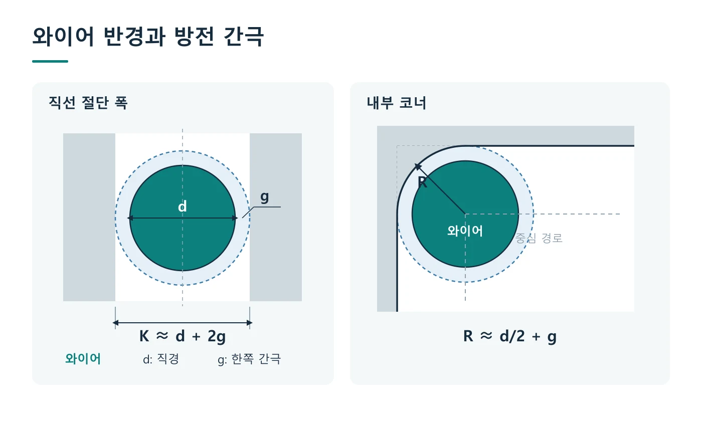
와이어 지름을 d, 한쪽 유효 방전 간극을 g라고 하면 단순한 평면 모델에서 유효 제거 반경은 d/2 + g로 표현할 수 있습니다. 같은 조건의 직선 절단 폭은 약 d + 2g입니다. 내부 코너의 이상적인 기하 한계를 설명할 때 지름 d와 반경 d/2를 혼동하지 않는 것이 출발점입니다.
예를 들어 지름 0.20 mm와 편측 간극 0.01 mm를 가정하면 유효 반경은 0.11 mm, 절단 폭은 0.22 mm입니다. 이는 계산 관계를 보여 주기 위한 가정값이며 실제 제품 사양이나 권장 가공 조건이 아닙니다. 이 계산만으로 완성 코너 R0.11을 보증할 수는 없습니다.
가공 한계와 품질 보증값의 차이
실제 간극은 방전 에너지, 재료, 가공액 상태와 패스 조건에 따라 변합니다. 와이어가 휘거나 진행 방향보다 늦게 따라오면 중심선의 실제 위치도 명령 경로와 달라집니다. 도면의 허용 R은 이상적인 제거 반경 위에 형상 오차와 공정 변동, 검사 불확도를 고려해 결정해야 합니다.
| 항목 | 의미 | 혼동하면 생기는 문제 |
|---|---|---|
| 와이어 지름 | 전극선 자체의 굵기 | 지름을 내부 R과 같다고 판단 |
| 편측 방전 간극 | 와이어 표면과 가공면 사이의 유효 간격 | 절단 폭에서 한쪽 간극만 반영 |
| 경로 오프셋 | 목표 윤곽과 와이어 중심 경로의 관계 | CAD·CAM·장비에서 보정을 중복 적용 |
| 코너 형상 오차 | 목표 곡선과 실제 윤곽의 차이 | 측정된 R 하나로 모든 오차를 설명 |
CAD가 완성품 윤곽을 전달하는지, CAM이 이미 중심 경로를 만든 것인지 먼저 확인합니다. 이후 장비의 보정값이 와이어 반경을 포함한 총 오프셋인지, 기준 조건에 더하는 미세 보정인지 구분합니다. 단위를 맞추는 것만으로는 부족하며 보정의 정의와 방향, 패스별 여유까지 같은 기준으로 관리해야 합니다.
02조립 간섭과 코너 설계
폭 공차와 코너 간섭
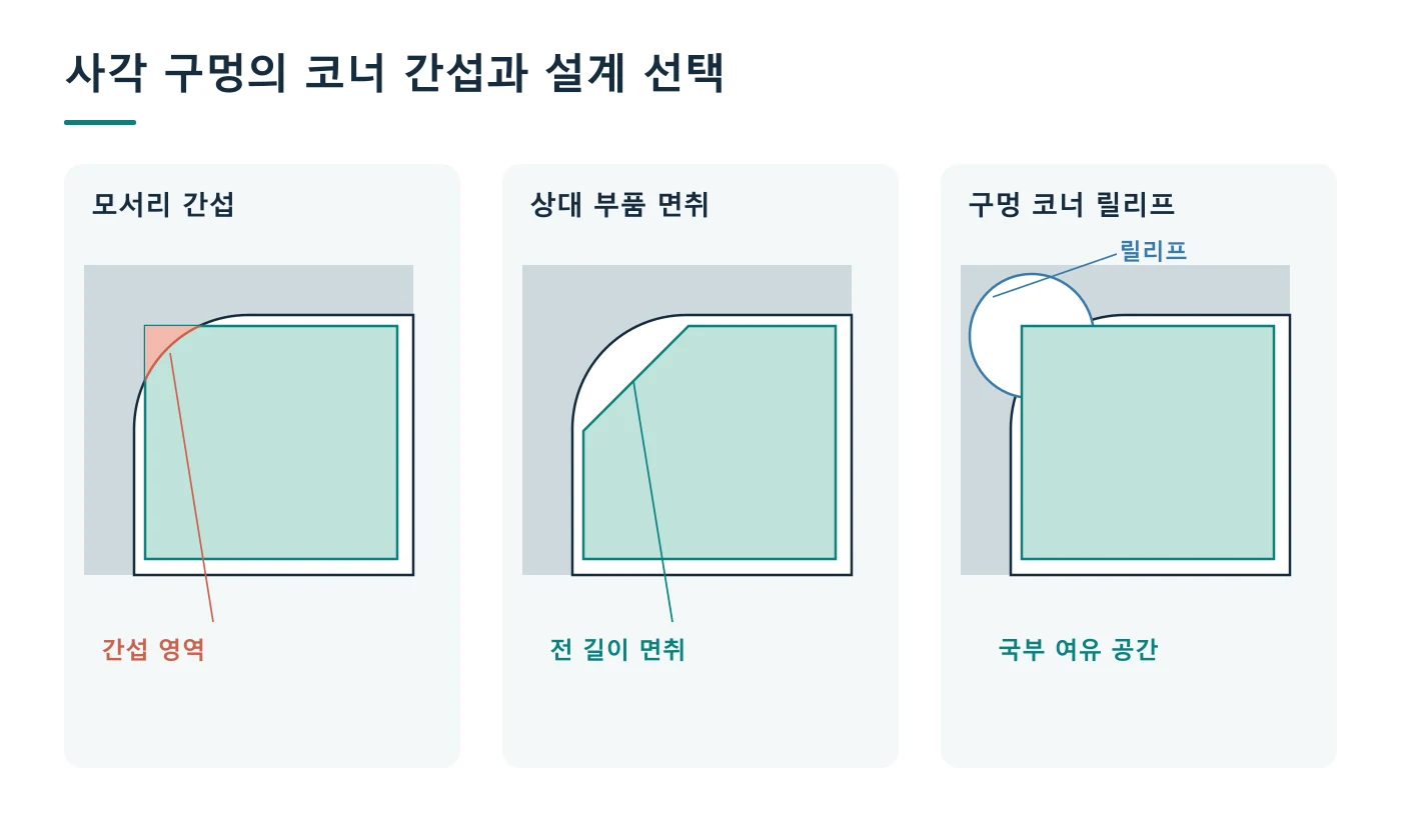
와이어 방전가공 내부 코너의 간섭은 사각 구멍의 폭과 높이가 상대 부품보다 커도 발생할 수 있습니다. 직선 벽 사이에는 틈이 있지만 내부 R이 이상적인 직각 모서리보다 구멍 안쪽으로 돌출하기 때문입니다. 상대 부품의 날카로운 외부 모서리가 그 잔여 재료와 먼저 접촉하면 직선부 치수는 합격해도 삽입되지 않습니다.
틈새는 전체 폭 차이와 편측 간극을 구분해야 합니다. 중심이 정확히 맞고 양쪽 틈새가 같다면 편측 간극은 전체 폭 차이의 절반입니다. 그러나 실제 위치결정이 한쪽 벽을 기준으로 이루어지거나 부품이 기울면 각 코너가 사용할 수 있는 여유는 서로 달라집니다.
직각 인서트의 간섭 예
이상적인 원호 코너 R0.50 mm와 날카로운 직각 인서트를 가정하겠습니다. 두 직선 벽에 대한 편측 간극이 각각 0.05 mm이면, 각 방향의 전체 폭 차이가 0.10 mm여도 코너에는 간섭이 남습니다. 이 평면 모델에서 두 방향 간극을 동일하게 늘리는 방법만 사용한다면, 간섭이 사라지는 경계는 편측 약 0.146 mm입니다.
이 값은 원호와 직각 모서리의 기하 관계에서 계산한 예시입니다. 치수 편차·형상 오차·기울기·표면처리·작동 여유는 포함하지 않았으므로 설계 허용값으로 바로 사용할 수 없습니다. 필요한 위치결정 정밀도가 높다면 구멍 전체를 키우기보다 상대 코너나 국부 릴리프를 바꾸는 쪽이 기능을 보존하기 쉽습니다.
간섭 해석은 공칭 모델끼리 한 번 맞추는 것으로 끝나지 않습니다. 구멍이 가장 작고 상대 부품이 가장 큰 상태, 허용되는 코너 형상, 위치·방향 편차를 조합해 확인합니다. 삽입 경로 전체와 최종 안착 상태를 각각 검토해야 중간 깊이에서 걸리는 문제도 찾을 수 있습니다.
상대 코너 수정과 국부 릴리프
코너 간섭을 해결하는 첫 번째 방법은 상대 부품의 외부 모서리에 적절한 라운드나 평면 모따기를 주는 것입니다. 두 번째는 구멍의 코너 부근에 재료를 추가로 제거하는 릴리프를 설계하는 방법입니다. 두 방식 모두 직선부의 위치결정 면을 유지하면서 충돌하는 부분만 바꿀 수 있지만, 실제 접촉 영역과 강도는 다시 검토해야 합니다.
입구 모따기와 길이 방향 모따기
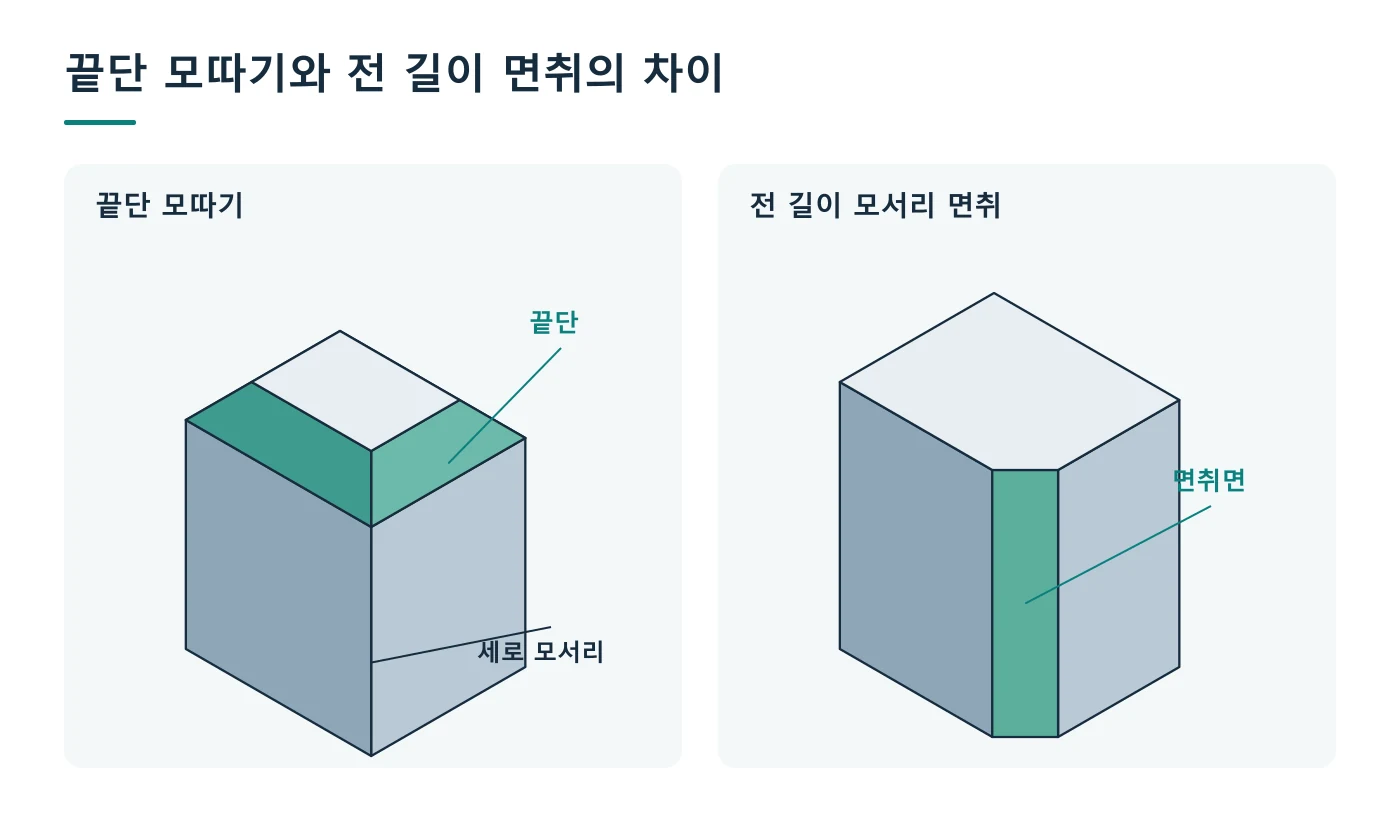
삽입 선단이나 구멍 입구 둘레에만 모따기를 주면 처음 진입할 때는 유리합니다. 그러나 그 뒤에 직각 단면이 그대로 이어지면 더 깊이 들어갈 때 동일한 코너 간섭이 다시 생깁니다. 관통 구간의 간섭을 해소하려면 실제 물림 길이 전체에 걸친 외부 코너 형상과 상대 내부 윤곽을 맞춰야 합니다.
45° 등변 모따기의 C 치수는 두 직교면에서 각각 재는 길이이므로, 코너의 대각선 방향 여유와 같은 값으로 취급하면 안 됩니다. 모따기 각도, 적용 모서리와 길이를 명확히 지정하고 최악 조건의 CAD 단면으로 검토합니다. 아주 작은 입구 모따기 표시 하나를 전 길이 코너 가공으로 해석하는 혼선을 방지해야 합니다.
| 설계 변경 | 보존할 수 있는 기능 | 추가 검토 |
|---|---|---|
| 상대 부품 외부 라운드 | 구멍의 원래 직선 기준면 | 양쪽 R·공차와 전체 삽입 경로 |
| 상대 부품 전 길이 모따기 | 주요 직선 위치결정 면 | 접촉 면적·방향·모따기 최소 크기 |
| 구멍의 국부 코너 릴리프 | 상대 부품의 직각 외형 | 주변 잔여 두께·응력 집중·밀봉 |
| 구멍 전체 확대 | 단순한 형상과 가공 경로 | 유격·회전·위치 반복성 |
릴리프는 관통 원형 여유부나 윤곽과 연결된 국부 확장 형태로 설계할 수 있습니다. 크기와 중심 위치를 정한 뒤 인접 구멍까지의 잔여 두께, 하중 전달 면, 반복 응력과 세척 접근성을 확인합니다. 밀봉 경로나 광학 차광면을 침범하는 형상은 조립성만 좋아져도 승인할 수 없습니다.
코너가 기능면에 포함되는 금형·게이지·미끄럼 안내부에서는 임의의 도그본 형상을 추가하지 않습니다. 비접촉 구역에서만 여유를 허용할지, 외부 코너를 바꿀지, 더 작은 와이어나 다른 가공법을 쓸지 설계 의도에 따라 선택합니다. 제조자가 편의를 위해 도면에 없는 홈을 추가하는 방식으로 해결해서는 안 됩니다.
03도면·소재·최종 상태
도면 기준과 코너 형상 공차
내부 R에 작은 숫자만 지정하면 조립 요구가 충분히 전달되지 않습니다. 설계에서는 어느 면이 위치를 정하는지, 어느 방향으로 삽입되는지, 코너가 접촉해야 하는지 먼저 구분합니다. 그다음 직선부 크기, 위치와 방향, 코너 전이부의 허용 형상을 연결해 규정합니다.
조립 간섭만 제한하려면 내부 R의 상한이 중요한 경우가 있습니다. 반대로 응력 집중이나 상대 코너 접촉을 관리하려면 하한과 전이 형상도 필요할 수 있습니다. R 최대값만 만족해도 국부 돌기·비접선 연결·직선 벽의 기울기가 남을 수 있으므로 기능에 따라 윤곽 공차를 함께 검토합니다.
치수·형상·위치의 분리
| 도면 항목 | 지정할 관계 | 검사에서 확인할 내용 |
|---|---|---|
| 폭·높이 | 기능 구간의 크기와 한계 | 코너를 피한 직선부와 깊이별 크기 |
| 기준면·기준 방향 | 조립 안착과 위치결정 관계 | 기준 정렬 후 위치·직각·평행 관계 |
| 코너 R·전이 윤곽 | 허용 반경과 재료 잔류 경계 | 원호 맞춤값뿐 아니라 전체 윤곽 편차 |
| 테이퍼·단면 | 두께 방향의 형상 관계 | 입구·중간·출구의 지정 단면 |
| 모서리·후처리 | 버 제거와 허용 에지 변화 | 최종 상태에서 기능면 보존 |
ISO GPS 체계의 기하공차는 크기뿐 아니라 형상·방향·위치 관계를 구분하는 언어입니다. 실제 도면에는 적용 표준과 기준을 일관되게 사용하고, 조립에서 정해진 구속을 검사 정렬에도 반영합니다. 기능 기준을 무시한 전체 최적맞춤은 부품의 위치 오차를 가려 보이게 할 수 있습니다.
상대 부품과의 간섭 판정에는 도면의 단품 합격 기준과 조립 검증 기준이 모두 필요합니다. 특정 상대물 하나에 들어갔다는 결과는 다른 허용 한계의 상대물과의 호환성을 보증하지 않습니다. 승인된 도면 개정, 상대물의 치수 범위와 판정 규칙을 같은 검증 기록에 연결해야 합니다.
소재·열처리·표면처리의 영향
방전가공은 전도성 소재를 대상으로 하며, 절삭 공구처럼 경도에 따른 기계적 절삭 저항만으로 난이도가 정해지지 않습니다. 열전도·용융 특성·조직과 가공액의 상호작용이 제거 속도와 표면 상태에 영향을 줍니다. 같은 강종이라도 열처리 상태와 이전 가공 이력이 다르면 초기품 검증 조건도 달라질 수 있습니다.
열처리된 공구강은 최종 열처리 뒤 기능 윤곽을 가공하는 경로를 검토할 수 있습니다. 다만 경화 후 가공한다는 사실만으로 치수 안정성이 완성되지는 않습니다. 소재의 잔류응력이 내부 형상 제거와 고정 해제에 따라 재분포하면 사각창의 폭이나 주변 프레임이 변형될 수 있습니다.
가공 순서와 최종 조립 상태
얇은 테두리나 긴 슬롯은 남은 단면의 강성이 작으므로 황가공 전후의 자유 상태를 비교합니다. 필요한 경우 소재 안정화, 대칭적인 제거 순서, 고정 위치와 중간 검사 단계를 검토합니다. 특정 대기 시간이나 열처리를 모든 강종에 일괄 적용하기보다 공급 상태와 승인 공정으로 조건을 정해야 합니다.
도금이나 코팅이 구멍 벽에 더해지면 내측 공간이 줄고 상대 부품의 외측 코팅은 외형을 키웁니다. 반대로 연마·에지 정리는 재료를 제거해 코너와 기준면을 바꿀 수 있습니다. 코팅이 코너에서 균일하게 쌓인다고 가정하지 말고 공정 전 여유와 최종 검사 기준을 연결합니다.
온도가 달라지면 구멍과 상대 부품의 크기도 달라집니다. 자유롭게 팽창하는 균일 소재에서는 구멍도 전체 형상과 함께 확대되지만, 조립 구속이나 서로 다른 재료·온도는 간극 변화의 방향을 바꿀 수 있습니다. 상온 단품 검사와 실제 사용 온도의 조립 여유를 분리해 확인해야 합니다.
가공면의 거칠기 수치와 표면 건전성은 서로 다른 품질 항목입니다. 보기 좋은 면이나 낮은 Ra만으로 재용융층·미세균열·부식 영향을 배제할 수 없습니다. 피로, 미끄럼, 금형 수명이 중요한 면에서는 해당 재료와 최종 패스·후처리를 묶어 검증 범위를 정합니다.
04가공 경로와 공정 제어
황삭·스킴 가공과 경로 보정
와이어 방전의 첫 절단은 큰 소재에서 필요한 윤곽을 분리하는 단계입니다. 이때 생산성을 확보하는 방전 조건과 최종 치수·표면을 얻는 조건은 다를 수 있습니다. 이후 스킴 가공은 이미 열린 절단면을 따라 적은 양의 소재를 제거하면서 형상과 표면을 다듬습니다. 필요한 패스 수는 재질, 두께, 요구 공차와 표면 상태를 함께 고려해 정합니다.
패스별 가공 여유와 방전 조건
스킴 가공은 황삭에서 남긴 여유를 계획적으로 제거해야 효과가 있습니다. 직선부와 코너의 잔여 소재가 크게 다르면 같은 설정으로 이동해도 실제 방전 부하가 달라집니다. 반대로 황삭에서 이미 최종 윤곽 밖으로 과도하게 제거한 부위는 후속 가공으로 복원할 수 없습니다. 최종 치수만 보고 패스를 추가하기보다 어느 위치에 얼마의 소재가 남는지부터 검토해야 합니다.
NC 보정값은 와이어 반지름만 입력하는 개념으로 이해하면 부족합니다. 실제로는 해당 패스의 유효 방전 간극과 남길 가공 여유가 경로 결정에 관여합니다. 도면 윤곽을 입력하고 제어기에서 보정하는 방식인지, CAM에서 이미 와이어 중심 경로를 계산했는지도 구분해야 합니다. 두 곳에서 같은 보정을 중복 적용하면 구멍 크기와 코너 연결부가 함께 달라질 수 있습니다.
| 확인 대상 | 구분할 내용 | 검증 방법 |
|---|---|---|
| 프로그램 기준 | 제품 윤곽과 와이어 중심 경로 | CAM 출력과 제어기 보정 방식을 대조합니다. |
| 패스별 조건 | 방전 에너지·간극·제거 여유 | 적용 기술 조건과 단계별 치수를 확인합니다. |
| 코너 구간 | 직선부 크기 오차와 국부 형상 오차 | 직선·진입부·원호·이탈부를 나누어 비교합니다. |
| 최종 보정 | 전체 오프셋과 위치별 제어 | 변경 전후의 같은 단면 윤곽을 겹쳐 봅니다. |
국부 오차와 전체 오프셋의 구분
직선부는 적합한데 코너만 맞지 않는다면 구멍 전체의 오프셋을 바꾸는 것은 신중해야 합니다. 직선부의 조립 틈새까지 변하기 때문입니다. 코너에서는 방향 전환에 따른 와이어 지연, 방전 집중과 유동 변화가 겹칠 수 있습니다. 장비가 제공하는 코너 제어와 패스별 기술 조건을 검토하고, 이송·방전·경로 중 무엇을 조정했는지 구분해 결과를 비교하는 편이 원인 파악에 유리합니다.
코너에서 무조건 속도를 낮추거나 동일 위치에 머무르게 하는 방식도 만능 해법은 아닙니다. 머무르는 동안의 방전 상태에 따라 국부 제거량이 달라질 수 있습니다. 시험 가공에서는 최종 R 하나뿐 아니라 직선과 원호가 만나는 부분의 꺾임, 입구와 출구의 차이, 두께 방향 윤곽을 함께 봅니다. 합격한 조건은 와이어·재질·두께·패스 순서와 묶어 기록해야 재현할 수 있습니다.
와이어 거동과 두께 방향 형상
와이어는 단단한 막대 공구가 아니라 위아래 가이드 사이에서 장력을 받는 가는 전극입니다. 가이드가 지령 경로를 따라 움직여도 가공 영역의 와이어는 방전과 유체의 힘을 받아 휘거나 뒤따라갈 수 있습니다. 따라서 평면상의 경로가 맞는 것과 절단 벽 전체가 같은 윤곽을 갖는 것은 별개의 문제입니다. 특히 방향이 바뀌는 코너에서는 이 차이를 확인해야 합니다.
장력·분사·유효 지지 길이
장력을 높이면 와이어의 횡방향 변위를 억제하는 데 도움이 될 수 있지만, 허용 장력을 넘겨 안정성을 확보하려 해서는 안 됩니다. 와이어 재질과 지름, 열적 부하, 가이드 상태와 장비의 적용 범위를 함께 봐야 합니다. 가이드와 공작물의 상대 위치도 기록합니다. 같은 재질과 두께라도 지지 조건이 달라지면 이전 조건을 그대로 적용했을 때의 코너 형상이 달라질 수 있습니다.
플러싱은 가공 틈새의 이물과 기포를 배출하고 안정적인 방전을 돕습니다. 그러나 분사 압력을 무조건 높이면 와이어에 작용하는 유체력도 커질 수 있습니다. 코너 전환, 열린 가장자리, 단차와 떨어진 노즐은 유동을 바꾸는 조건입니다. 분사량만 조정하기보다 상하 노즐의 접근 상태, 절단 틈새와 배출 경로를 함께 살펴야 안정성과 형상을 동시에 평가할 수 있습니다.
상면과 하면의 치수가 비슷해도 중간 높이의 벽이 오목하거나 볼록할 수 있습니다. 반대로 위아래의 크기가 점차 달라지는 테이퍼도 발생할 수 있습니다. 와이어의 거동 외에 초기 수직 정렬, 의도된 테이퍼 설정, 고정 변형과 소재 내부 응력의 해방도 구분해야 합니다. 공작물을 고정한 상태와 해제한 상태에서 형상이 달라지면 방전 조건만으로 해결할 문제인지 다시 판단합니다.
시작 구멍과 코어 지지
닫힌 내부 윤곽은 와이어를 통과시킬 시작 구멍과 가공 진입 경로가 필요합니다. 시작 구멍은 제거될 영역 안에 두고, 진입·이탈 흔적이 기능 코너나 정밀 맞춤면에 남지 않도록 경로를 검토합니다. 구멍 위치뿐 아니라 와이어가 실제로 통과할 공간, 자동 결선 가능 여부, 진입부에서 최종 윤곽으로 연결되는 방식도 공정 계획에 포함해야 합니다.
마지막 연결부가 잘릴 때 내부 코어가 움직이면 와이어 끼임, 단선 또는 완성 벽의 손상으로 이어질 수 있습니다. 코어 지지, 장비의 코어 고정 기능, 임시 연결부를 남기는 순서 중 적합한 방법을 미리 정합니다. 임시 연결부를 사용한다면 그 부위를 제거한 뒤 정밀 윤곽을 완성하는 방법도 필요합니다. 코어 처리와 최종 검사를 같은 공정표에 넣어야 마지막 단계의 손상을 놓치지 않습니다.
05표면 품질과 형상 검사
표면 건전성과 기능 모서리 보존
방전가공은 국부적인 열로 소재를 제거합니다. 용융된 물질 중 일부가 표면에 다시 굳으면 재응고층이 남을 수 있으며, 그 아래의 변화와 미세균열 발생 여부는 재질과 방전 조건에 따라 달라집니다. 눈에 보이는 거칠기나 색만으로 이 층의 깊이와 건전성을 판정할 수는 없습니다. 또한 특정 합금 시험에서 관찰된 표면 현상을 모든 방전 부품의 특성으로 일반화하면 안 됩니다.
거칠기와 재응고층의 구분
낮은 에너지의 마무리 패스는 황삭 표면의 거칠기와 열적 영향을 줄이는 데 활용됩니다. 다만 스킴 가공 횟수만으로 재응고층이나 균열이 완전히 없어졌다고 보증할 수는 없습니다. 반복 하중, 피로, 부식 또는 민감한 접촉면이 문제되는 용도라면 어떤 표면 상태를 허용할지 먼저 정하고, 필요할 때 동일 재질·공정의 시편 단면 관찰 등으로 확인해야 합니다.
후연마로 표면을 개선할 때는 제거되는 소재가 기능 치수에 미치는 영향을 계산에 넣어야 합니다. 내부 벽을 연마하면 구멍이 커지고, 코너를 둥글게 문지르면 직선과 원호의 연결 형상이 달라집니다. 좁은 코너는 평면과 같은 양이 제거된다고 가정하기도 어렵습니다. 후처리가 필요한 경우에는 허용 제거량, 연마 가능한 면과 보존할 윤곽을 도면 또는 공정 지시에서 구분합니다.
| 요구 기능 | 확인할 표면 항목 | 후처리 시 주의점 |
|---|---|---|
| 정밀 끼워맞춤 | 국부 돌출·윤곽·접촉 흔적 | 벽면 제거량과 코너 형상 변화를 함께 관리합니다. |
| 반복 하중 | 재응고층·균열 등 용도별 중요 항목 | 거칠기 개선만으로 피로 성능을 단정하지 않습니다. |
| 조립 취급 | 입구 모서리·이탈 흔적·잔류 이물 | 손에 닿는 모서리와 기능 코너의 마감 요구를 구분합니다. |
| 후속 표면처리 | 청정도·처리 후 최종 치수 | 코팅 또는 연마가 끝난 상태에서 조립 조건을 확인합니다. |
모서리 마감과 최종 세척
와이어 방전에는 일반 절삭에서처럼 공구가 소재를 밀어내며 만드는 버가 적지만, 이를 모든 모서리에 손볼 부분이 없다는 뜻으로 받아들이면 안 됩니다. 시작 구멍, 임시 연결부 제거 흔적, 잔류 입자와 날카로운 입구 모서리를 각각 확인합니다. 특히 도면에 정한 내부 R을 보존해야 하는 부위까지 일괄적으로 모따기하거나 텀블링하면 조립을 좌우하는 형상이 달라질 수 있습니다.
최종 확인은 세척과 건조를 마친 상태에서 진행합니다. 틈새에 남은 가공 잔류물은 실제 간섭처럼 느껴질 수 있고, 공격적인 세척이나 수작업 연마는 표면 상태를 다시 바꿀 수 있습니다. 필요한 청정도와 재질에 맞는 세척 방식을 정하고, 중요한 맞춤면에는 처리 전후의 치수와 외관을 연결해 기록합니다. 포장에서도 완성 코너가 다른 부품과 부딪히지 않도록 보호합니다.
표면 지표의 의미는 Ra·Rz·Rt의 차이와 검사 기준으로 구분하고, 잔류 이물과 세척 이력은 정밀부품 세척과 청정도와 연결해 관리합니다. 표면 수치, 외관과 오염 상태는 서로를 대신하는 합격 증거가 아닙니다.
코너 윤곽과 조립 기능의 검사
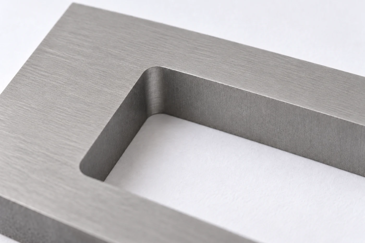
내부 코너 검사는 R 수치 하나를 구하는 일과 같지 않습니다. 원호가 있어야 할 위치, 직선부와 연결되는 접선 방향, 윤곽의 국부 돌출까지 조립에 영향을 줍니다. 측정 전에 기준면과 기준 방향을 잡고 어떤 단면의 어느 범위를 평가할지 정합니다. 설계 윤곽에 대한 편차를 보면 평균 반지름만으로 드러나지 않는 간섭 부위를 찾는 데 도움이 됩니다.
원 맞춤과 실제 윤곽 편차
측정점에 원을 맞추는 계산은 선택한 점과 맞춤 방식에 따라 결과가 달라집니다. 짧은 원호 일부만 측정하거나 직선 연결부의 돌출을 제외하면 양호한 R 값이 나와도 실제 끼워맞춤은 불량할 수 있습니다. 반지름 보고가 필요한 경우에도 측정 범위와 점 분포를 함께 정하고, 기능적으로 중요한 전체 윤곽의 편차를 별도로 확인하는 것이 좋습니다.
투영기와 영상측정기는 작은 평면 윤곽을 관찰하는 데 유용하지만 조명, 초점, 표면 반사와 에지 검출 설정의 영향을 받습니다. 두꺼운 관통 구멍을 위에서 본 영상은 특정 높이의 단면인지, 여러 높이의 윤곽이 겹친 투영인지도 구분해야 합니다. 입구가 잘 보인다는 이유만으로 내부 벽 전체가 적합하다고 판정하지 말고, 필요한 높이에 접근할 수 있는 측정 방법을 선택합니다.
접촉식 CMM은 프로브 볼과 스템이 평가할 코너까지 접근할 수 있어야 합니다. 볼이 너무 크면 좁은 오목부를 따라가지 못하고, 가늘고 긴 스타일러스는 강성과 측정 안정성에서 제약을 받습니다. 소프트웨어의 프로브 반지름 보정은 실제로 접촉하지 못한 형상을 복원하지 못합니다. 필요한 접근성을 만족하는 범위에서 짧고 강성 있는 구성과 적절한 볼 크기를 선택하고 측정 조건을 검증합니다.
| 검사 질문 | 필요한 정보 | 놓치기 쉬운 항목 |
|---|---|---|
| 코너가 도면과 맞는가 | 기준에 정렬한 윤곽 편차 | 접선 연결부의 국부 돌출 |
| 두께 전체가 맞는가 | 접근 가능한 상·중·하 단면 비교 | 상하면 사이의 오목·볼록 형상 |
| 측정 방법이 충분한가 | 분해능·접근성·불확도·측정 조건 | 프로브 간섭과 영상의 투영 효과 |
| 상대 부품이 조립되는가 | 관리된 상대 부품 또는 기능 게이지 | 한 쌍의 조립 성공을 호환성 보증으로 해석하는 오류 |
온도 조건과 기능 확인
미세한 틈새를 비교할 때는 온도 조건도 형상 평가의 일부입니다. 가공 직후의 부품과 검사실에 충분히 둔 부품은 같은 상태가 아닐 수 있습니다. 치수의 기준 온도와 실제 온도, 재질의 열팽창 특성, 부품 내부의 온도 차이를 고려합니다. 필요한 안정화 시간은 크기와 열 이력에 따라 달라지므로 모든 부품에 같은 대기시간을 적용하는 방식보다 실제 조건을 확인하는 편이 타당합니다.
조립 시험은 윤곽 측정을 보완합니다. 삽입 방향과 힘, 접촉 위치를 관리해 시험하면 실제 걸림을 찾는 데 도움이 됩니다. 다만 우연히 잘 맞는 상대 부품 한 개로 검사하면 치수 편차의 불리한 조합을 놓칠 수 있습니다. 교환 가능한 부품이 필요하다면 도면의 공차 범위와 일치하는 판정 기준을 두고, 윤곽 데이터와 기능 확인 결과를 함께 남깁니다.
06공정 선택과 발주 기준
미세 와이어와 공정 비용의 선택
작은 내부 R을 위해 가는 와이어를 선택하면 도달 가능한 형상 범위가 넓어집니다. 그러나 지름만 바꾸면 같은 생산성과 안정성이 유지되는 것은 아닙니다. 적용 가능한 장력과 방전 조건, 가이드와 결선 장치의 대응, 공작물 두께를 함께 검토해야 합니다. 특정 장비에서 가능한 최소 와이어 지름이 해당 부품의 최소 코너 R을 그대로 보증하지도 않습니다.
필요 형상과 총 공정 시간
비용은 절단 길이만으로 설명되지 않습니다. 시작 구멍 준비, 결선, 코어 처리, 황삭과 스킴 패스, 측정과 후처리가 전체 시간을 구성합니다. 작은 R 때문에 가는 와이어를 사용하면서 여러 패스와 까다로운 검사가 추가되면 짧은 윤곽도 제작 부담이 커질 수 있습니다. 견적 비교에서는 동일한 완성 상태와 검사 범위가 포함되었는지 확인해야 합니다.
기능이 허용한다면 내부 R의 확대, 상대 부품의 모서리 수정, 코너 릴리프 또는 분할 구조가 대안이 될 수 있습니다. 이 선택은 가공비만이 아니라 유효 접촉 면적, 남는 벽 두께, 강성·응력집중과 조립 방향까지 함께 평가해야 합니다. 특히 조립을 쉽게 하려고 추가한 릴리프가 하중을 받는 모서리에 새로운 취약부를 만들지 않는지 설계 단계에서 검토합니다.
| 선택안 | 적용 검토점 | 함께 고려할 부담 |
|---|---|---|
| 일반 와이어와 형상 완화 | 기능상 R 확대 또는 상대 모서리 수정 가능성 | 접촉 면적·강성·설계 변경 |
| 미세 와이어 | 작은 코너와 좁은 형상의 필요성 | 장비 대응·결선·가공 안정성·검사 |
| 형조 방전 | 막힌 형상 또는 와이어 통과가 어려운 구조 | 전극 제작·마모·배출 조건·코너 보정 |
| 브로칭·슬로팅 등 | 형상 접근성·소재·수량과 전용 공구의 적합성 | 절삭력·공구 형상·고정·입출구 공간 |
| 분할 후 조립 | 접합부를 허용할 수 있는 기능 | 조립 오차·접합 강성·부품 수 |
대체 공정의 형상 한계
막힌 포켓처럼 와이어를 관통시킬 수 없는 형상은 일반적인 관통 와이어 가공과 공정 조건이 다릅니다. 형조 방전은 전극 형상을 이용해 접근할 수 있지만, 전극의 코너와 방전 간극·마모 때문에 무조건 날카로운 내각을 보장하지는 않습니다. 대체 공정을 검토할 때도 최종 코너, 깊이와 표면 요구를 함께 제시하고 실제 접근 경로를 확인해야 합니다.
최종 선택은 가장 작은 R을 만드는 공정보다 필요한 기능을 안정적으로 검증할 수 있는 공정에 맞춥니다. 시제품은 셋업과 검사 비용의 비중이 크고, 반복 생산은 조건 재현성과 자동 처리 가능성이 중요해집니다. 서로 다른 공정의 견적을 비교할 때는 가공 완료 치수, 후처리 포함 여부와 합격 판정 방식까지 같게 맞춰야 합리적인 비교가 됩니다.
도면 협의와 불량 원인의 검증
제작 협의에서는 사각 구멍의 폭·길이와 내부 R만 전달하는 것으로 부족할 수 있습니다. 재질과 열처리 상태, 두께, 기준면, 윤곽의 허용 범위, 조립 상대의 형상과 삽입 방향이 필요합니다. 어떤 면이 위치를 결정하고 어느 코너가 접촉하면 안 되는지를 설명하면 가공업체가 기능과 무관한 부분까지 과도하게 정밀 가공하는 일을 줄일 수 있습니다.
완성 상태와 검사 조건의 합의
도면의 치수가 방전 직후 기준인지, 연마·코팅·세척 후 기준인지 먼저 맞춥니다. 허용할 모서리 마감과 코너 릴리프, 외관 기준도 같은 문서에서 구분합니다. 검사가 까다로운 작은 내각은 측정 가능한 단면과 방법, 조립 또는 기능 게이지의 사용 여부를 사전에 정해야 합니다. 제작이 끝난 뒤 서로 다른 측정 방법으로만 합격 여부를 논의하면 원인 규명이 어려워집니다.
초도 검증에서는 대표 시편이나 실제 부품으로 기능 코너의 윤곽과 조립을 함께 확인합니다. 검사 결과에는 기준 정렬, 측정 높이, 후처리 상태와 중요한 가공 조건을 연결합니다. 한 번 합격한 조건도 와이어 종류·지름, 소재 두께 또는 고정 방식이 바뀌면 재검토가 필요할 수 있습니다. 변경 전후의 영향 범위를 정해 검증하면 불필요한 전면 재시험을 줄이면서 핵심 기능을 지킬 수 있습니다.
| 증상 | 먼저 분리할 원인 | 확인할 데이터 |
|---|---|---|
| 직선부는 맞지만 코너에서 걸림 | 설계상 간섭·국부 윤곽 오차·잔류 이물 | 상대 코너와 실측 윤곽, 세척 전후 접촉 위치 |
| 입구는 통과하나 안쪽에서 걸림 | 두께 방향 형상·테이퍼·부품 기울기 | 여러 높이의 윤곽과 삽입 자세 |
| 고정 해제 후 형상이 변함 | 고정 변형·잔류응력 해방·온도 차이 | 고정 전후 치수와 측정 온도 |
| 특정 코너만 흔적이 심함 | 진입·이탈부·코어 이동·국부 방전 조건 | 가공 경로와 해당 위치의 표면 확대 관찰 |
| 검사자 또는 장비별 판정이 다름 | 기준·측정 높이·검출 또는 맞춤 방식 | 동일 부품의 원시 측정점과 평가 조건 |
증상별 원인 분리와 재확인
조립이 안 된다는 이유로 구멍 전체를 키우기 전에 걸리는 위치를 찾습니다. 코너의 국부 간섭인지, 직선부의 틈새 부족인지, 중간 높이의 형상 문제인지에 따라 필요한 수정이 달라집니다. 세척, 기준 정렬과 온도 조건을 확인한 뒤 같은 측정 방법으로 형상을 비교하면 가공 문제와 검사 문제를 구분하기 쉽습니다. 수정은 원인과 연결되는 항목부터 단계적으로 적용합니다.
수정 후에는 문제가 있던 코너뿐 아니라 인접 직선부와 반대편의 조립 여유도 다시 확인합니다. 보정이나 후처리는 다른 위치의 형상까지 바꿀 수 있기 때문입니다. 최종 기록에는 채택한 도면 개정, 가공 조건, 후처리와 검사 결과를 한 흐름으로 연결합니다. 이렇게 해야 내부 R을 작게 만든 사실을 넘어, 필요한 위치결정과 조립 기능이 반복해서 유지되는지를 판단할 수 있습니다.
와이어 방전가공 내부 코너의 품질은 도면의 의도와 실제 조립 기능이 같은 기준으로 이어질 때 판단할 수 있습니다. 제품문의·개발의뢰에서는 완성품 도면에 상대 부품의 형상과 검사 요구를 함께 제공하면 코너 변경, 공정 선택과 검증 범위를 구체적으로 협의할 수 있습니다.
English Edition · Wire EDM Internal Corners
Internal corners in wire EDM retain a rounded transition related to electrode radius and discharge gap. Even when a rectangular opening meets its width and height requirements, this transition can interfere with a mating corner. Enlarging the whole opening may reduce interference while sacrificing positioning accuracy and support area.
The design objective is functional corner clearance and a verifiable profile, rather than a small radius alone. Wire-and-gap geometry, full-length mating chamfers, local relief, through-thickness form and final inspection conditions must be defined together. Geometric comparisons and illustrative calculations explain these relationships.
Radius and gap
Wire diameter, one-sided discharge gap and path compensation are distinct quantities.
Section and engagement
Separate wall clearance from corner interference and check the full engagement length.
Profile and final inspection
Verify form, location, depth-dependent variation and final finishing, as well as radius.
01How internal radii form
Through profiles and the origin of internal radii
Wire EDM removes material through repeated discharges between a thin electrode wire and an electrically conductive workpiece. Unlike a rotating cutter, the wire maintains a small machining gap from the surface. The finished contour therefore reflects the wire center path together with the electrode radius and discharge gap.
A right-angle CAD contour does not allow a wire of finite diameter to create an infinitely sharp internal corner. A rounded transition remains. Assembly depends on the size and actual shape of this transition and whether it interferes with the mating component.
Through windows, blind pockets and external corners
Conventional wire EDM forms a contour with the wire passing through the workpiece. It suits through windows and external profiles. A closed internal contour requires a threading hole or an approved entry route. A blind pocket with a retained floor requires a different process, such as sinker EDM or cutting.
External convex corners have different geometric constraints because the wire can travel around the outside of the part. Wire lag, excessive discharge and finishing can still alter them. The internal-radius limit should not be transferred directly to external corners, nor should an external edge be guaranteed to have zero radius.
The respective roles of wire cutting and start-hole machining are discussed in wire EDM and fine-hole EDM process selection. Distinguishing the through-contour operation from hole preparation helps connect entry-route planning with geometric requirements.
Wire diameter, discharge gap and path compensation
Let d be wire diameter and g the effective discharge gap on one side. In a simplified planar model, the effective removal radius is d/2 + g. The corresponding straight-cut kerf is approximately d + 2g. Distinguishing diameter d from radius d/2 is essential when explaining the ideal geometric limit of an internal corner.
For illustration, a wire diameter of 0.20 mm and a one-sided gap of 0.01 mm give an effective radius of 0.11 mm and a kerf of 0.22 mm. These assumed values demonstrate the calculation; they are not product specifications or recommended settings. The calculation alone does not guarantee a finished R0.11 corner.
Geometric limits versus guaranteed results
The actual gap changes with discharge energy, material, dielectric condition and pass settings. Wire deflection and lag also separate the actual wire position from the commanded path. A drawing radius must accommodate contour error, process variation and inspection uncertainty beyond the ideal removal radius.
| Item | Meaning | Risk of confusion |
|---|---|---|
| Wire diameter | Size of the electrode itself | Treating diameter as the internal radius |
| One-sided discharge gap | Effective space between wire surface and cut face | Including only one gap in the kerf |
| Path offset | Relationship between target contour and wire center path | Applying compensation twice across CAD, CAM and machine |
| Corner form error | Deviation of the actual contour from its target | Using one fitted radius to describe every error |
First establish whether CAD supplies the finished contour or CAM has already generated a center path. Then distinguish a total machine offset, including wire radius, from a fine correction added to a baseline. Consistent units are not enough: define compensation, its direction and pass allowances on the same basis.
02Assembly interference and corner design
Width tolerances and corner interference
A rectangular opening can be wider and taller than its mating part yet still prevent assembly. Clearance exists between the straight walls, but the internal radius retains material inside the ideal square corner. A sharp external corner can contact this material even when the straight-wall dimensions pass inspection.
Distinguish the overall width difference from clearance on each side. With perfect centering and equal gaps, one-sided clearance is half the width difference. If the part locates against one wall or tilts, however, the available clearance differs at each corner.
An illustrative sharp-corner insert
Consider an ideal R0.50 mm opening and a sharp-cornered rectangular insert. Equal one-sided clearances of 0.05 mm leave corner interference, despite an overall size difference of 0.10 mm in each direction. If equal clearance is the only variable changed, the ideal planar non-interference threshold is approximately 0.146 mm per side.
This is a geometric illustration based on a circular corner and a sharp insert. It excludes dimensional variation, form error, tilt, surface treatment and operating clearance, so it cannot be used directly as a design limit. Where location accuracy matters, modifying the mating corner or adding local relief may preserve function better than enlarging the entire opening.
A single nominal CAD assembly is insufficient. Evaluate the smallest opening, largest mating part, permitted corner geometry and allowed position and orientation errors together. Check the entire insertion path as well as final seating to detect interference at intermediate depths.
Mating-corner changes and local relief
One approach is to add a suitable radius or planar chamfer to the mating external corner. Another is to remove additional material locally at the opening corner. Both can preserve straight locating surfaces while changing the interfering region, but contact area and strength require reassessment.
Entry chamfers versus longitudinal corner chamfers
A chamfer at the leading end or around the opening mouth helps initial entry. If a sharp rectangular section continues behind it, the same corner interference returns deeper into insertion. Clearing the engaged region requires compatible external-corner and internal-profile geometry over the entire engagement length.
For an equal-leg 45° chamfer, C denotes the length measured on each perpendicular face, not diagonal corner clearance. Define the angle, affected edges and length, then examine worst-case CAD sections. A small entry-edge chamfer callout should not be interpreted as a full-length corner modification.
| Design change | Function that may be retained | Additional review |
|---|---|---|
| External mating radius | Original straight opening datums | Both radii, tolerances and insertion path |
| Full-length mating chamfer | Principal straight locating faces | Contact area, orientation and minimum chamfer size |
| Local opening relief | Square exterior of the mating part | Remaining ligament, stress concentration and sealing |
| Larger opening throughout | Simple geometry and machining path | Play, rotation and positioning repeatability |
Relief can take the form of a through circular clearance or a local extension connected to the profile. After defining its size and location, check the remaining ligament to adjacent features, load-bearing surfaces, cyclic stresses and cleaning access. Improved assembly alone does not justify relief that cuts through a sealing path or optical baffle surface.
Do not add arbitrary dog-bone relief where the corner is functional, such as in a die, gauge or sliding guide. Decide whether clearance is allowed only in a noncontact region, whether the mating corner can change, or whether finer wire or another process is needed. Manufacturing convenience does not authorize an unapproved groove.
03Drawings, materials and final condition
Drawing datums and corner-profile tolerances
A small internal-radius value alone does not adequately communicate assembly requirements. First identify the locating faces, insertion direction and whether the corner must make contact. Then connect straight-section size, position and orientation with the permitted corner-transition profile.
An upper radius limit may be important when preventing assembly interference. A lower limit and transition shape may also matter for stress concentration or mating-corner contact. A maximum-radius requirement alone does not exclude local protrusions, nontangent joins or tilted straight walls, so consider profile control where function requires it.
Separate size, form and location
| Drawing item | Relationship to specify | Inspection evidence |
|---|---|---|
| Width and height | Limits over the functional region | Straight sections and size at specified depths |
| Datums and directions | Seating and locating relationships | Position, squareness and parallelism after alignment |
| Corner radius and transition | Permitted radius and material boundary | Full contour deviation as well as fitted radius |
| Taper and sections | Geometry through the thickness | Specified entry, middle and exit sections |
| Edges and finishing | Deburring and permitted edge change | Preserved functional surfaces in the final condition |
Geometric tolerancing in the ISO GPS system distinguishes form, orientation and location from size. Use a consistent standard and datum scheme, and reflect assembly constraints in inspection alignment. An unrestricted best fit that ignores functional datums can obscure positional error.
Interference assessment requires both individual drawing acceptance criteria and assembly criteria. Fitting one particular mating part does not guarantee interchangeability with another part at its permitted limits. Link the approved drawing revision, mating dimensional range and decision rule in the validation record.
Material, heat treatment and surface finishing
EDM requires electrical conductivity, and difficulty is not governed solely by hardness-related mechanical cutting resistance. Thermal conductivity, melting behavior, microstructure and dielectric interactions affect removal and surface condition. Even within one grade, heat treatment and previous processing can change the conditions requiring initial-part validation.
For hardened tool steel, machining the functional profile after final heat treatment may be appropriate. This alone does not establish dimensional stability. Residual stress can redistribute as the internal shape is removed and clamping is released, changing opening width or distorting the surrounding frame.
Process sequence and final assembly condition
Thin rims and long slots have limited remaining stiffness, so compare free-state geometry before and after roughing. Consider material stabilization, balanced removal, clamp locations and intermediate inspection where needed. Set conditions from the supplied material state and approved process rather than imposing one waiting time or heat treatment on every grade.
Plating or coating on opening walls reduces internal space, while coating on the mating exterior increases its envelope. Polishing and edge finishing remove material and can change corners or datum faces. Do not assume uniform buildup at corners; connect pre-finish allowances to final inspection requirements.
Temperature changes the opening and mating-part dimensions. A hole expands with the surrounding geometry in a freely expanding homogeneous material, but assembly constraints, different materials or unequal temperatures can change how clearance evolves. Separate room-temperature component inspection from assembly clearance at service temperature.
Surface roughness and surface integrity are distinct quality characteristics. An attractive appearance or low Ra does not rule out recast material, microcracks or corrosion effects. For fatigue-critical, sliding or die surfaces, define validation around the material, final passes and finishing process together.
04Machining paths and process control
Roughing, skim cuts and path compensation
The first wire EDM cut separates the required contour from the surrounding stock. Discharge conditions that support productive rough cutting may differ from those needed for the final dimensions and surface. Subsequent skim cuts follow the already opened surface and remove a small amount of material to refine its form and finish. The required number of passes depends on material, thickness, tolerance and surface requirements together.
Stock allowance and discharge conditions for each pass
A skim cut is effective when it removes a planned allowance left by roughing. If the remaining stock differs greatly between a straight section and a corner, the actual discharge load changes even with the same programmed settings. Material already removed beyond the final contour during roughing cannot be restored by later cuts. Before adding another pass based only on the final dimension, examine where stock remains and how much remains there.
It is insufficient to understand NC compensation simply as entering the wire radius. The effective discharge gap for the pass and the stock allowance also influence the required path. Distinguish between programming the drawing contour with compensation in the controller and using a wire-center path already calculated by CAM. Applying the same compensation twice can alter both the opening size and the transitions into its corners.
| Review item | Required distinction | Verification method |
|---|---|---|
| Programming basis | Part contour versus wire-center path | Compare the CAM output with the controller compensation method. |
| Conditions for each pass | Discharge energy, gap and removal allowance | Check the applied machining technology and dimensions at each stage. |
| Corner region | Straight-section size error versus local form error | Compare the straight section, approach, arc and exit separately. |
| Final correction | Global offset versus local control | Overlay the same section before and after the change. |
Separating local errors from global offsets
If the straight sections are acceptable but a corner is not, changing the global opening offset requires care. It also changes the assembly clearance along the straight walls. At a corner, wire lag during a direction change can interact with concentrated discharges and changes in fluid flow. Review the machine’s corner control and pass-specific machining technology. Comparing results while distinguishing changes to feed, discharge and path makes diagnosis more effective.
Always reducing speed or dwelling at a corner is not a universal remedy either. Local removal can change with the discharge state during the dwell. A trial cut should assess more than one final radius value: examine the transition between the straight wall and arc, differences between the approach and exit, and the contour through the thickness. To reproduce an accepted result, record the settings together with the wire, material, thickness and pass sequence.
Wire behavior and form through the thickness
The wire is a slender electrode held under tension between upper and lower guides, rather than a rigid cutting tool. Even when the guides follow the commanded path, the wire in the cutting zone can bend or lag under discharge and fluid forces. A correct path in the programmed plane does not therefore establish that the entire cut wall has the same contour. This distinction deserves particular attention at corners where the direction changes.
Tension, flushing and effective support span
Increasing tension can help resist lateral wire displacement, but stability must not be pursued by exceeding the permitted tension. Wire material and diameter, thermal load, guide condition and the machine’s operating range must be considered together. Record the positions of the guides relative to the workpiece as well. Even with the same material and thickness, changed support conditions can alter corner form when an earlier setting is reused.
Flushing removes debris and bubbles from the machining gap and supports stable discharge. However, indiscriminately raising flushing pressure can also increase the fluid force acting on the wire. Corner transitions, open edges, steps and separated nozzles all change the flow conditions. Evaluating nozzle access above and below the part, the cut gap and the discharge path together is more useful than adjusting flow alone when both stability and form matter.
Similar dimensions at the top and bottom do not exclude a concave or convex wall at an intermediate height. Alternatively, the opening may taper as its size changes from top to bottom. In addition to wire behavior, distinguish initial vertical alignment, intentional taper settings, clamping deformation and release of stress within the stock. If the form changes after unclamping, reconsider whether discharge settings alone can solve the problem.
Start holes and slug support
A closed internal contour requires a start hole for threading the wire and an entry path into the cut. Place the hole within the material to be removed and review the path so that entry or exit marks do not remain at a functional corner or precision mating surface. Process planning must address not only the hole position but also the actual threading space, automatic threading feasibility and the transition from the entry path to the final contour.
When the final connection is severed, movement of the internal slug can pinch or break the wire or damage a finished wall. Plan a suitable method in advance, such as slug support, a machine core-retention function or a sequence that temporarily retains a connecting tab. If a tab is used, also define how the precision contour will be completed after its removal. Including slug handling and final inspection in the same process plan helps prevent damage at the last stage from being overlooked.
05Surface quality and profile inspection
Surface integrity and preservation of functional edges
EDM removes material through localized thermal action. Some molten material can resolidify on the surface and form a recast layer. Changes beneath that layer and the presence of microcracks depend on the material and discharge conditions. Visible roughness or color alone cannot establish the depth or integrity of this layer. Surface features observed in a test on one alloy must not be generalized to every EDM component.
Distinguishing roughness from the recast layer
Low-energy finishing passes can be used to reduce rough-cut surface roughness and thermal effects. The number of skim cuts alone does not guarantee complete removal of the recast layer or cracks. Where cyclic loading, fatigue, corrosion or a sensitive contact surface is relevant, define the acceptable surface condition first. When needed, verify it through methods such as cross-sectional examination of a specimen made with the same material and process.
When polishing is used to improve the surface, account for the material removal in the functional dimensions. Polishing an internal wall enlarges the opening, while rounding a corner by rubbing changes the transition between the straight section and the arc. A confined corner cannot be assumed to lose the same amount of material as a flat surface. Where post-processing is required, distinguish the permitted removal, surfaces that may be polished and contours that must be preserved in the drawing or process instructions.
| Required function | Surface characteristics to check | Post-processing consideration |
|---|---|---|
| Precision fit | Local projections, contour and contact marks | Control wall removal and corner-form changes together. |
| Cyclic loading | Application-critical characteristics such as recast layer and cracks | Do not infer fatigue performance from improved roughness alone. |
| Assembly handling | Entrance edges, exit marks and residual debris | Distinguish handling-edge requirements from functional-corner requirements. |
| Subsequent surface treatment | Cleanliness and final dimensions after treatment | Check assembly conditions after coating or polishing is complete. |
Edge finishing and final cleaning
Wire EDM produces little of the tool-displacement burr typical of conventional cutting, but this does not mean that every edge requires no attention. Inspect start holes, marks from tab removal, residual particles and sharp entrance edges separately. Applying a general chamfering or tumbling operation to areas where the specified internal radius must be preserved can change the form that governs assembly.
Perform the final check after cleaning and drying. Machining residue in a narrow gap can be mistaken for geometric interference, while aggressive cleaning or manual polishing can change the surface again. Select a cleaning method suited to the required cleanliness and material. For critical mating surfaces, link dimensional and visual records before and after treatment. Packaging should also protect finished corners from contact with other parts.
Distinguish surface parameters using the Ra, Rz and Rt inspection guide, and connect residual contamination and cleaning history to precision-part cleanliness. Surface parameters, appearance and contamination condition are not interchangeable acceptance evidence.
Inspection of corner profiles and assembly function
Inspecting an internal corner is not equivalent to obtaining a single radius value. Assembly also depends on the arc position, the tangent direction at its transition to the straight wall and local contour projections. Before measurement, establish the datum and orientation and define the section and region to be evaluated. Deviations from the design contour can help reveal interference that an average radius alone does not expose.
Circle fitting and actual profile deviation
A circle fitted to measured points depends on both the selected points and the fitting method. Measuring only a short part of an arc or excluding a projection at the straight-wall transition can produce an acceptable radius while the actual fit remains unacceptable. Even when a radius must be reported, define the measured region and point distribution and separately examine deviation over the complete functionally important profile.
Profile projectors and vision measuring systems are useful for small planar contours, but illumination, focus, surface reflections and edge-detection settings affect the result. For a thick through-opening viewed from above, distinguish a section at a particular height from a projection that combines contours at different heights. A clear view of the entrance does not establish conformity of the entire internal wall. Select a method that can access the required heights.
A tactile CMM requires both the probe ball and stem to reach the corner being evaluated. A ball that is too large cannot follow a narrow concavity, while a slender, long stylus has limitations in stiffness and measurement stability. Software compensation for probe radius cannot reconstruct a feature that was never physically contacted. Within the required access constraints, select a short, stiff configuration and suitable ball size, then validate the measurement conditions.
| Inspection question | Required information | Frequently overlooked issue |
|---|---|---|
| Does the corner match the drawing? | Profile deviation aligned to the datum | Local projections at tangent transitions |
| Is the full thickness acceptable? | Comparison of accessible top, middle and bottom sections | Concave or convex form between the end faces |
| Is the measurement method adequate? | Resolution, access, uncertainty and measurement conditions | Probe interference and image-projection effects |
| Does the mating part assemble? | A controlled mating part or functional gauge | Mistaking successful assembly of one pair for guaranteed interchangeability |
Temperature conditions and functional verification
Temperature is part of the assessment when small clearances are being compared. A part measured immediately after machining may not be in the same state as one that has stabilized in the inspection room. Consider the dimensional reference temperature, actual temperature, material expansion and temperature gradients within the part. Required stabilization time depends on size and thermal history, so checking the actual conditions is more appropriate than imposing the same waiting time on every part.
An assembly test complements profile measurement. Controlling insertion direction, force and contact location helps identify actual binding. However, checking against one fortuitously matching component can miss unfavorable combinations of dimensional variation. If interchangeability is required, establish acceptance criteria consistent with the drawing tolerances and retain both profile data and the functional verification result.
06Process selection and purchasing requirements
Fine-wire selection and process cost
Selecting a finer wire for a small internal radius expands the geometries that can be reached. Changing diameter alone does not preserve the same productivity and stability, however. Review the applicable tension and discharge conditions, guide and threading compatibility, and workpiece thickness together. The smallest wire diameter supported by a particular machine does not directly guarantee the smallest corner radius of the actual part.
Required geometry and total process time
Cost cannot be explained by cut length alone. Start-hole preparation, threading, slug handling, roughing and skim passes, inspection and post-processing all contribute to total time. A short contour can become demanding when a small radius requires fine wire, multiple passes and difficult inspection. When comparing quotations, check that they cover the same final condition and inspection scope.
Where function permits, alternatives include increasing the internal radius, modifying the mating corner, adding corner relief or using a split construction. Evaluate these options against effective contact area, remaining wall thickness, stiffness, stress concentration and assembly direction, as well as machining cost. In particular, review whether relief added to ease assembly creates a new weak region at a loaded corner.
| Option | Applicability review | Additional considerations |
|---|---|---|
| Conventional wire with relaxed geometry | Whether function permits a larger radius or modified mating corner | Contact area, stiffness and design changes |
| Fine wire | Need for small corners and narrow features | Machine compatibility, threading, stability and inspection |
| Sinker EDM | Blind features or structures difficult to thread through | Electrode production, wear, debris evacuation and corner compensation |
| Broaching, slotting or related cutting | Feature access, material, quantity and suitability of dedicated tooling | Cutting forces, tool geometry, workholding and entry/exit space |
| Split construction and assembly | Whether the function permits a joint | Assembly errors, joint stiffness and part count |
Geometric limits of alternative processes
A blind pocket that cannot be threaded through has different process requirements from conventional through-cut wire EDM. Sinker EDM can approach it with a shaped electrode, but electrode corners, discharge gap and wear prevent it from unconditionally guaranteeing a sharp internal corner. When considering an alternative process, specify the final corner, depth and surface requirements together and verify the actual access path.
The final choice should favor a process that can reliably deliver and verify the required function, rather than merely produce the smallest radius. Setup and inspection account for a large share of prototype work, while repeat production places more emphasis on reproducible conditions and automated handling. Quotations for different processes are comparable only when final dimensions, included post-processing and acceptance methods are aligned.
Drawing review and verification of defect causes
A manufacturing review may require more than the width, length and internal radius of a rectangular opening. Material and heat-treatment condition, thickness, datums, permissible contour variation, mating geometry and insertion direction are also relevant. Explaining which surfaces locate the assembly and which corners must remain clear helps prevent unnecessarily tight machining of features unrelated to function.
Agreement on final condition and inspection
First align whether the drawing dimensions apply immediately after EDM or after polishing, coating and cleaning. Distinguish permitted edge finishing, corner relief and appearance requirements in the same documentation. For a small internal corner that is difficult to inspect, agree in advance on accessible sections, measurement methods and any assembly or functional-gauge check. Discussing acceptance only after production using different measurement methods makes diagnosis harder.
Initial validation should check both the functional corner profile and assembly using a representative specimen or actual part. Link the result to datum alignment, measurement height, post-processing state and important machining conditions. Previously accepted settings may require review when wire type or diameter, stock thickness or workholding changes. Defining the affected scope before and after a change can preserve critical function without unnecessary repetition of every test.
| Symptom | Causes to distinguish first | Data to examine |
|---|---|---|
| Straight sections fit but a corner binds | Design interference, local form error or residual debris | Mating-corner geometry, measured contour and contact location before and after cleaning |
| Entrance passes but insertion binds deeper inside | Form through the thickness, taper or part tilt | Profiles at several heights and insertion orientation |
| Form changes after unclamping | Clamping deformation, stress release or temperature difference | Dimensions before and after release and measurement temperature |
| Pronounced marks at one corner | Entry/exit location, slug movement or local discharge conditions | Toolpath and magnified surface observation at that location |
| Acceptance differs by inspector or instrument | Datum, height, detection or fitting method | Raw points and evaluation conditions for the same part |
Separating causes and checking the result
Locate the binding point before enlarging an entire opening merely because assembly fails. Local corner interference, insufficient straight-wall clearance and a form error at an intermediate height require different corrections. After checking cleanliness, datum alignment and temperature, comparing the geometry with the same measurement method helps separate machining problems from inspection problems. Apply corrections progressively, starting with the variables connected to the identified cause.
After correction, recheck the adjacent straight sections and clearance on the opposite side as well as the original problem corner. Compensation or post-processing can also change geometry elsewhere. The final record should connect the accepted drawing revision, machining conditions, post-processing and inspection results. This makes it possible to judge whether the required locating and assembly functions are maintained repeatedly, beyond merely establishing that a small internal radius was produced.
Internal-corner quality in wire EDM can be assessed when drawing intent and assembly function are connected by consistent criteria. Providing the mating geometry and inspection requirements with the finished-part drawing through product and development inquiries supports a specific discussion of corner changes, process selection and validation scope.
추가 정보
검색엔진용 요약
와이어 방전가공 내부 코너는 유한한 전극 반경과 방전 간극, 실제 와이어 거동에 의해 형성됩니다. 사각 구멍의 직선부 크기와 코너 간섭을 나누어 검토하고, 상대 부품의 전 길이 코너 가공 또는 승인된 국부 릴리프로 기능 여유를 설계합니다. 최종 품질은 R뿐 아니라 윤곽·위치·두께 방향 형상·표면 건전성과 후처리 상태로 검증합니다.
핵심 포인트 정리
- 이상적인 유효 제거 반경과 실제 가공 보증 R을 구분합니다.
- 전체 폭 차이와 편측 간극은 서로 다른 값입니다.
- 입구나 끝단만 모따기하면 깊은 구간의 코너 간섭은 남을 수 있습니다.
- 릴리프는 위치결정 면·잔여 두께·하중·밀봉 경로를 검토해 승인합니다.
- 경로 보정과 방전 조건은 패스별로 연결하며 중복 보정을 피합니다.
- 상면 윤곽만으로 중간 깊이와 하면의 형상을 보증하지 않습니다.
- 검사는 최종 후처리 상태와 기능 기준에 맞춰 진행합니다.
FAQ
와이어 방전가공으로 내부 R0을 만들 수 있나요?
일반적인 원형 와이어와 유한한 방전 간극을 사용하면 내부 오목 코너에는 둥근 전이부가 남습니다. 필요한 형상에 따라 더 작은 와이어, 상대 코너 변경, 국부 릴리프나 다른 가공법을 검토합니다. R0이라는 표현만으로 제조·검사 기준을 정하지 않습니다.
와이어 지름을 내부 코너 반경으로 보면 되나요?
지름과 반경을 구분해야 합니다. 단순한 평면 모델의 유효 반경은 와이어 반경과 편측 유효 방전 간극의 합으로 설명할 수 있습니다. 실제 허용 R은 와이어 거동, 형상 오차와 검사 조건까지 반영해야 합니다.
사각 구멍이 상대 부품보다 큰데 왜 들어가지 않나요?
직선 벽 사이에 틈새가 있어도 내부 R의 잔여 재료가 상대 부품의 날카로운 외부 모서리와 충돌할 수 있습니다. 코너 형상, 위치·방향 편차와 전체 삽입 경로를 함께 대조합니다.
입구에 모따기만 하면 간섭이 없어지나요?
입구 모따기는 처음 진입을 돕지만 깊은 구간의 단면은 바꾸지 않을 수 있습니다. 실제로 물리는 길이 전체에서 상대 코너와 내부 윤곽이 호환되는지 확인해야 합니다.
스킴 가공을 여러 번 하면 모든 코너 오차가 없어지나요?
패스 수만으로 보증할 수 없습니다. 황삭의 남은 여유, 과제거, 와이어 휨, 방전과 세척 조건이 영향을 줍니다. 이미 제거한 재료는 후속 가공으로 복원할 수 없으므로 단계별 윤곽을 확인합니다.
R 측정값이 합격이면 조립도 합격인가요?
맞춤 원의 반경만으로 국부 돌기나 직선 연결부, 위치·방향 및 두께 방향 오차를 모두 판단할 수 없습니다. 도면 기준에 정렬한 윤곽 검사와 필요한 조립 검증을 구분합니다.
견적 의뢰에 어떤 자료가 필요한가요?
최종 도면과 3D 모델, 상대 부품의 형상·허용 범위, 재질·열처리·두께, 코너의 기능, 릴리프 허용 여부, 후처리와 검사 기준을 함께 전달합니다. 승인되지 않은 형상 변경은 사전에 협의합니다.
관련 주제 확장 설명
작은 R과 위치결정 기능
구멍 전체를 확대하면 삽입은 쉬워져도 유격과 회전 여유가 커질 수 있습니다. 직선 기준면을 유지하면서 비접촉 코너만 수정할 수 있는지 우선 검토합니다.
표면거칠기와 표면 건전성
Ra 등 표면거칠기는 형상의 미세 요철을 평가하는 지표입니다. 재용융층·미세균열·부식은 별도의 검증 항목이며 모든 제품에 같은 시험을 요구하기보다 기능과 재료에 맞춰 정합니다.
검사 정렬과 합격 판정
측정 데이터의 최적맞춤과 실제 조립 기준 정렬은 다른 결과를 줄 수 있습니다. 기준 체계, 단면 위치와 측정 불확도에 대한 합의가 있어야 제조자와 구매자가 같은 결과를 해석할 수 있습니다.
내부 링크
공정의 기본 구분은 와이어컷팅과 슈퍼드릴의 형상 가공 기준, 검사 항목은 CNC 가공 공차와 정밀도와 함께 확인할 수 있습니다.
표면 평가에는 표면거칠기 Ra·Rz·Rt, 최종 취급에는 정밀부품 세척과 청정도가 연결됩니다. 도면·상대물·검사 범위 협의는 제품문의·개발의뢰를 통해 진행할 수 있습니다.