
CNC 표면거칠기 Ra·Rz·Rt 차이: 도면 기호와 가공·검사 기준
표면거칠기와 기능
CNC 표면거칠기는 가공면의 광택을 표현하는 외관 등급이 아니라 부품 기능과 제조 공정을 연결하는 설계 요구사항입니다. 치수 공차를 만족한 부품도 표면 상태가 맞지 않으면 마찰, 밀봉, 윤활, 피로수명, 도금과 도장 밀착성에서 문제가 발생할 수 있습니다.
표면 텍스처는 미세하고 촘촘한 요철인 거칠기(roughness), 비교적 긴 주기의 굴곡인 파상도(waviness), 가공 흔적의 주된 방향인 가공결(lay)로 구분합니다. 평면의 기울기, 원통의 곡률과 휨 같은 형상 성분도 측정 프로파일에 함께 나타나므로 요구한 스케일만 분리해 평가해야 합니다.
Ra가 같더라도 한 표면은 완만한 요철로, 다른 표면은 날카로운 돌기와 깊은 골로 구성될 수 있습니다. 평균값 하나만으로 누설 가능성, 실제 접촉면적, 오일 유지성과 마모 거동을 모두 판단할 수 없습니다. 기능에 맞춰 Ra, Rz, Rt와 가공결, 필요한 추가 파라미터를 선택해야 하며 Ra를 무조건 낮추는 것이 항상 좋은 설계는 아닙니다.
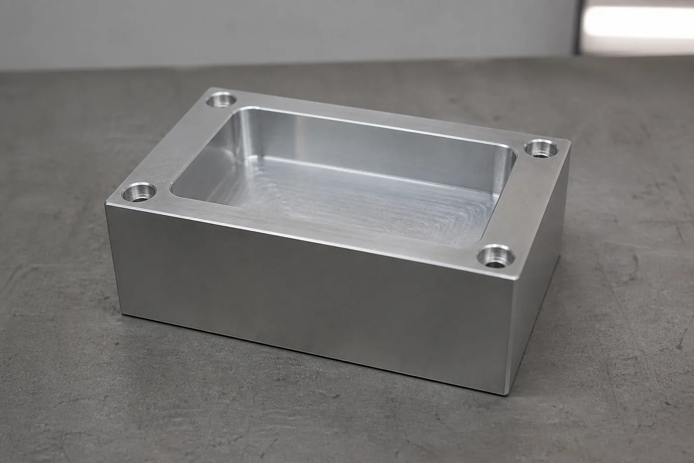
프로파일 분리
측정된 원시 프로파일에는 형상, 파상도, 거칠기와 측정 노이즈가 함께 들어 있습니다. ISO 21920 계열은 어떤 스케일의 프로파일을 평가하는지 구분하기 위해 P, W, R 기호를 사용합니다.
P-profile은 명목 형상과 짧은 스케일 성분에 필요한 처리를 적용해 얻는 기본 프로파일입니다. W-profile은 짧은 파장의 거칠기 성분을 제한해 비교적 긴 주기의 굴곡을 나타냅니다. R-profile은 파상도와 더 긴 파장 성분을 제한해 미세한 표면 요철을 나타냅니다. Ra, Rz, Rt의 첫 글자 R은 모두 R-profile에서 계산한다는 뜻입니다.
F-operator는 직선, 원호 등의 명목 형상을 제거합니다. Profile S-filter는 측정 노이즈와 지나치게 짧은 스케일 성분을 제한하고, profile L-filter는 거칠기와 파상도를 나누는 경계를 만듭니다. 필터 종류나 경계 길이가 달라지면 물리적으로 같은 표면도 다른 값으로 평가될 수 있습니다.
접촉식 장비의 스타일러스 팁도 기계적인 필터로 작용합니다. 팁보다 좁은 골은 완전히 추종하지 못하고 큰 팁은 날카로운 형상을 둥글게 읽을 수 있습니다. Pz, Wt, Ra처럼 기준 프로파일이 다른 값은 숫자가 비슷해도 서로 대체할 수 없습니다.
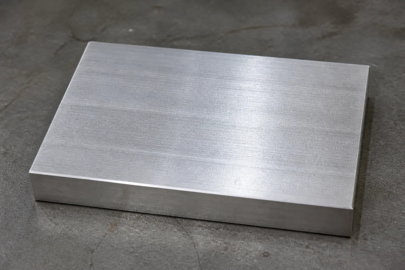
Ra·Rz·Rt 차이
Ra, Rz, Rt는 모두 높이 방향의 표면 특성을 나타내지만 계산 방식과 이상점에 대한 민감도가 다릅니다. 일반 공정 관리에는 Ra가 편리하고, 구간별 peak와 valley 변화를 보려면 Rz가 유용하며, 평가 길이에서 발생한 최악의 높이차를 제한하려면 Rt가 적합합니다.
| 파라미터 | 계산 개념 | 주요 용도 | 주의점 |
|---|---|---|---|
| Ra | 평가 길이에서 평균선 기준 높이 편차 절댓값의 산술평균 | 일반 가공 품질, 공정 추세, 공급자 간 기본 비교 | 단일 scratch·돌기와 peak·valley의 비대칭이 평균 속에 가려질 수 있습니다. |
| Rz | 각 section length의 최대 peak-to-valley 높이를 산출한 뒤 평균하며 기본 section 수는 5개 | 구간별 요철 크기와 peak·valley 변화 감시 | 평가 길이 전체에서 발생한 단 하나의 최악 결함값은 아닙니다. |
| Rt | 평가 길이 전체의 가장 높은 peak와 가장 깊은 valley 사이 높이차 | 단일 scratch, burr, 돌기 또는 깊은 골이 기능을 해치는 면 | 오염, 이상점, 위치와 평가 길이에 민감해 산포가 커질 수 있습니다. |
Ra와 Rz 사이에 계약 판정에 사용할 수 있는 보편적인 고정 환산비는 없습니다. 같은 Ra에서도 공구 형상, 이송, 진동, 재료 찢김과 profile 분포에 따라 Rz와 Rt가 크게 달라집니다. 경험적인 배수 관계는 초기 추정에만 제한적으로 사용하고 요구 파라미터를 직접 측정해야 합니다.
실링면, 슬라이딩면, 윤활 유지면처럼 기능이 중요한 표면은 Rp, Rv, Rsk, RSm, Rmr 또는 Rk·Rpk·Rvk 계열과 가공결도 함께 검토하는 것이 안전합니다. Legacy Rmax, Rz1max와 현행 Rzx(l)도 Rt와 같은 뜻으로 간주하지 말고 도면의 적용 표준을 확인해야 합니다.
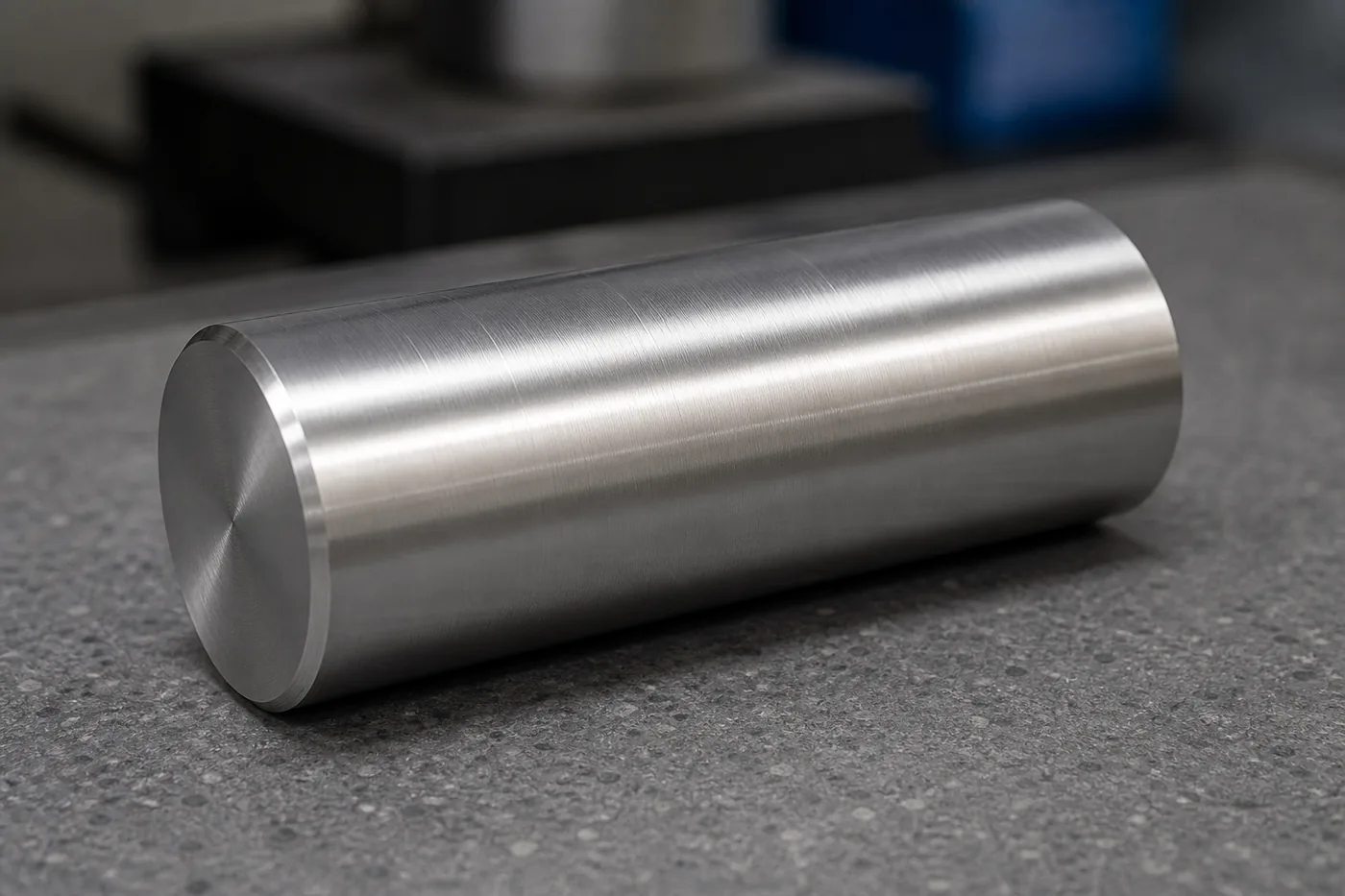
필터와 평가 길이
표면거칠기 값은 어느 길이 범위의 형상을 거칠기로 분류했는지에 따라 달라집니다. 기존 도면의 cutoff wavelength λc는 ISO 21920에서 profile L-filter nesting index Nic라는 개념으로 일반화됐습니다. Gaussian 선형 필터에서는 Nic와 기존 λc를 수치적으로 대응시킬 수 있지만 nesting index는 비선형 필터까지 포괄합니다.
평가 길이 le는 파라미터 계산에 사용하는 길이이며, section length lsc는 Rz처럼 구간 단위로 계산하는 파라미터에 사용합니다. 스타일러스의 실제 traverse length는 필터의 시작·끝 효과와 접근 구간 때문에 le보다 길 수 있습니다.
| 항목 | Sc1 | Sc2 | Sc3 | Sc4 | Sc5 |
|---|---|---|---|---|---|
| Ra 상한 U | ≤ 0.02 µm | > 0.02–0.1 µm | > 0.1–2 µm | > 2–10 µm | > 10 µm |
| Rz 상한 U | ≤ 0.16 µm | > 0.16–0.8 µm | > 0.8–16 µm | > 16–80 µm | > 80 µm |
| Rt 상한 U | ≤ 0.26 µm | > 0.26–1.3 µm | > 1.3–26 µm | > 26–130 µm | > 130 µm |
| Nic | 0.08 mm | 0.25 mm | 0.8 mm | 2.5 mm | 8 mm |
| le | 0.4 mm | 1.25 mm | 4 mm | 12.5 mm | 40 mm |
| Nis | 2.5 µm | 2.5 µm | 2.5 µm | 8 µm | 25 µm |
| lsc / nsc | 0.08 mm / 5 | 0.25 mm / 5 | 0.8 mm / 5 | 2.5 mm / 5 | 8 mm / 5 |
표의 값은 Ra, Rz, Rt 등의 상한 공차 U가 지정되고 별도 측정 조건이 없을 때 적용하는 기본값입니다. 하한 공차와 양측 공차에는 별도 선택 규칙이 있으며, 도면에 필터나 setting class가 명시됐다면 그 지시가 우선합니다.
예를 들어 ISO 21920 기준의 단순한 Ra 0.8 µm 상한은 Sc3이므로 기본 Nic 0.8 mm와 le 4 mm를 사용합니다. Ra 3.2 µm 상한은 Sc4에 해당해 Nic 2.5 mm와 le 12.5 mm가 기본입니다. 모든 가공면을 관행적으로 0.8 mm cutoff로 측정하면 도면과 다른 결과가 나올 수 있습니다.
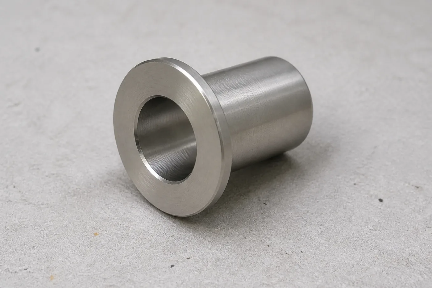
측정 방향과 위치
선형 표면거칠기 측정은 방향에 민감합니다. 특별한 지시가 없으면 스타일러스는 일반적으로 주된 가공결에 직각으로 이동시켜 높이 변화가 크게 나타나는 방향을 평가합니다. 도면에서 profile direction이나 가공결 방향을 지정했다면 해당 지시가 최우선입니다.
선삭 외경에서는 나선형 이송 흔적을 가로지르는 방향, 밀링면에서는 공구 경로나 scallop을 가로지르는 방향이 대표적인 검사 방향이 될 수 있습니다. 복합 공구 경로, 교차 가공결과 5축 자유곡면은 한 방향의 Ra만으로 표면 전체를 대표하기 어렵습니다. 기능 방향별 복수 trace 또는 ISO 25178 계열의 면적 파라미터 Sa를 검토할 수 있습니다.
공구 진입부와 이탈부, 얇은 벽, 코너, 클램핑 부근과 chatter가 시작되는 구간은 중앙부와 다른 거칠기를 보일 수 있습니다. 기능상 중요한 위치와 최대값이 예상되는 위치를 도면 또는 검사계획에 지정해야 합니다.
접촉식과 광학식 결과도 자동으로 같아지지 않습니다. 스타일러스 팁 반경, 광학 장비의 경사·반사율 대응, 데이터 보간과 필터 구현이 다르기 때문입니다. 양산 승인값을 비교하려면 acquisition method와 측정 조건까지 고정해야 하며 line parameter Ra와 areal parameter Sa를 같은 값처럼 비교해서도 안 됩니다.
밀링·선삭·연삭 조도
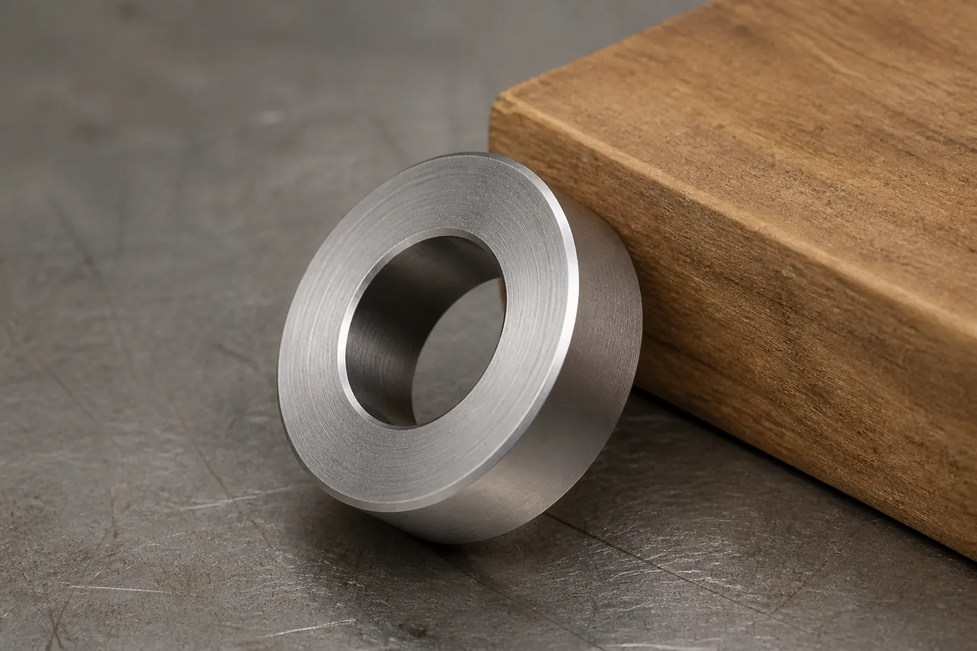
공정별 조도 범위는 설계 초기의 가공성 검토와 견적에 유용하지만 합격 보증값은 아닙니다. 소재와 경도, 공작기계 강성, 공구 돌출과 runout, 날끝 마모, 이송, 절입량, 냉각, 치구와 진동 상태가 실제 결과를 결정합니다.
| 공정 | 조건부 참고 범위 | 주요 영향 요인 | 설계·검사 주의점 |
|---|---|---|---|
| 선삭 | 관리된 finish pass에서 Ra 약 0.8–3.2 µm가 흔하며 안정된 조건과 wiper 형상에서는 더 낮아질 수 있습니다. | 이송, nose radius, insert 형상, built-up edge, runout, chatter | 이론적인 feed mark 높이는 실제 Ra가 아니며 큰 nose radius가 진동을 일으키면 오히려 악화될 수 있습니다. |
| 밀링 | 관리된 finish 가공에서 Ra 약 0.8–3.2 µm가 흔하지만 공구 경로와 형상에 따라 폭이 큽니다. | 날당 이송, step-over, 공구 직경, 날높이 편차, tool runout, 절삭 방향 | 평면 밀링과 ball-end 자유곡면은 같은 Ra 목표라도 scallop과 측정 방향이 다릅니다. |
| 정밀 연삭 | Ra 약 0.1–0.8 µm 또는 그 이하가 가능하며 거친 연삭은 더 높을 수 있습니다. | 숫돌 입도·결합도, dressing, wheel balance, 이송, 냉각, 열손상 | 낮은 Ra와 연삭 burn 또는 인장 잔류응력이 없는지는 별도 품질 항목입니다. |
| 호닝·슈퍼피니시 | 실린더 호닝 사례는 Ra 약 0.2–1 µm이며 전문 superfinish는 0.1 µm 미만도 가능합니다. | stone 입도, 압력, 교차각, 단계 수, 전처리 거칠기 | 오일 유지용 valley와 plateau가 필요하므로 Ra를 무조건 낮추는 것이 목적은 아닙니다. |
| EDM | 단일 범위로 일반화하기 어렵고 roughing과 다단 skim·finishing 조건의 차이가 큽니다. | 방전 에너지, pulse 조건, 전극·wire, dielectric, skim 횟수 | 특수 장비의 초미세 수치를 일반적인 EDM 양산 능력으로 적용하지 않아야 합니다. |
선삭의 이상적인 요철 높이는 이송의 제곱에 비례하고 nose radius가 커질수록 감소하지만 이 관계는 공구의 기하학적 궤적만 설명합니다. 재료의 소성 유동, 공구 마모, 절삭날 용착, 진동과 기계 오차를 포함하지 않으므로 Ra, Rz 또는 Rt의 검사값을 직접 계산하는 식으로 사용할 수 없습니다.
밀링은 평균 Ra뿐 아니라 공구 경로의 주기성, step-over 흔적과 국부 단차를 확인해야 합니다. 연삭은 숫돌 dressing과 열 관리가 중요하며 매우 낮은 Ra가 연삭 burn이나 표면층 손상이 없다는 의미는 아닙니다.
도면 표기와 규격
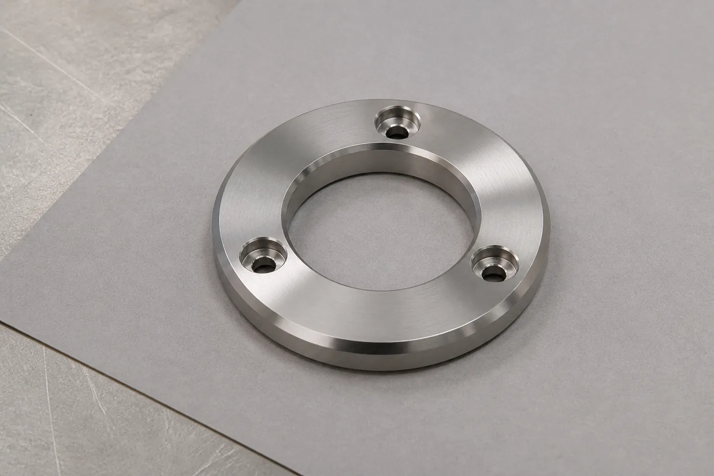
ISO 21920-1은 프로파일 표면 텍스처의 도면 표기를, ISO 21920-2는 용어와 파라미터를, ISO 21920-3은 specification operator와 기본 측정 조건을 규정합니다. 새 도면에는 적용 표준과 판을 title block 또는 기술 사양서에 기록하는 것이 좋습니다.
Ra, Rz, Rt처럼 기본값이 정의된 파라미터는 graphical symbol, 파라미터 기호와 한계값으로 최소 표기가 가능합니다. 예를 들어 Ra 0.8 µm를 최소 표기하면 별도 지시가 없는 항목에는 ISO 21920-3의 상한 공차, Tmax와 해당 setting class 기본값이 적용됩니다.
그래픽 기호는 공정 제한 없음, material removal 필수, material removal 금지의 의미를 구분합니다. 기능상 중요한 면에는 U 또는 L 공차 유형과 양측 한계, Tmax·T16%·Tmed acceptance rule, Nic·Nis, le 또는 lsc/nsc, profile direction, 가공법, 가공결과 acquisition method까지 필요한 항목을 추가합니다.
ASME 도면은 ASME B46.1의 표면 텍스처 정의와 ASME Y14.36의 기호 체계를 따릅니다. ISO 기본 측정 조건을 ASME 도면에 자동 적용하거나 반대로 적용하면 안 됩니다. 파라미터 없는 숫자, 삼각형 개수, N 등급만 남은 legacy 표기는 도면의 적용 표준과 사내 규정을 확인한 뒤 해석해야 합니다.
ISO 규격 전환
ISO 21920-1/-2/-3:2021은 2026년 8월 현재 발행된 현행 프로파일 표면 텍스처 시리즈입니다. ISO 1302:2002, ISO 4287:1997, ISO 4288:1996의 역할을 각각 이어받았습니다. 2026년에 심의된 2판 committee draft는 아직 발행 표준이 아니므로 확정 규격처럼 적용하면 안 됩니다.
기존 ISO 4288 방식은 프로파일을 periodic 또는 nonperiodic으로 판단하고 예상되거나 측정된 Ra, Rz, RSm을 기준으로 cutoff를 선택했습니다. ISO 21920은 이 구분을 없애고 도면에 지정된 tolerance와 setting class를 중심으로 기본 측정 조건을 정합니다. 설계 사양이 measurement operator를 결정하므로 검사자가 예비 측정 후 유리한 cutoff를 고르는 방식은 적절하지 않습니다.
Acceptance rule도 달라졌습니다. 구 ISO 1302·4288 체계에서 별도 표기가 없을 때 기본은 16% rule이었지만 ISO 21920의 기본은 maximum rule인 Tmax입니다. T16%는 한계값에 16%를 더한다는 뜻이 아니라 정해진 절차에서 제한된 비율의 측정값 초과를 허용하는 규칙이며 사용하려면 명시해야 합니다. Tmed는 측정값 중앙값을 이용하는 별도의 규칙입니다.
새 규격은 별도 제외 지시가 없는 표면 불완전부도 평가 범위에 포함하는 방향이 기본입니다. 다만 먼지와 절삭유 잔류물 같은 외부 오염은 제거한 뒤 측정합니다. 구 도면은 표준이 철회됐다는 이유만으로 새 기본값으로 바뀌지 않으므로 도면에 적힌 표준과 발행연도를 그대로 적용해야 합니다.
검사 반복성
서로 다른 검사자가 같은 부품에서 비교 가능한 결과를 얻으려면 파라미터 이름만 맞춰서는 부족합니다. 표준과 판, profile 종류, 필터, Nic·Nis, le, lsc/nsc, 스타일러스 팁 반경, 측정 속도, 방향, 위치와 form 제거 조건을 함께 일치시켜야 합니다.
측정 전에는 절삭유, 먼지와 느슨한 입자를 제거하고 부품과 장비의 온도를 안정시킵니다. 스타일러스 팁의 마모·손상, skid 또는 datum 방식, 장비 레벨링과 교정 상태도 확인합니다. 거칠기 비교 시편은 장비 상태 점검에는 유용하지만 실제 부품의 곡률, 재질, 가공결과 측정 접근성을 모두 대신하지는 못합니다.
반복 측정은 같은 선을 계속 긁기보다 합의된 기능 위치의 인접 trace와 여러 부품을 평가하는 방식이 적절합니다. 연질 재료는 접촉 측정 자체가 표면을 바꿀 수 있습니다. Tmed에는 최소 세 개 이상의 측정값이 필요하며 Tmax 사양은 평균값이 한계 이내라는 이유로 개별 초과값을 무시할 수 없습니다.
검사 성적서에는 결과와 단위뿐 아니라 적용 표준·판, 파라미터와 profile, 필터와 길이, probe 또는 광학 방식, 측정 방향·위치, 반복 횟수, acceptance rule과 장비 식별정보를 남기는 것이 좋습니다. 한계 부근의 값은 반올림만으로 판정하지 말고 측정 불확도와 합의된 decision rule을 함께 검토해야 합니다.
양산 승인
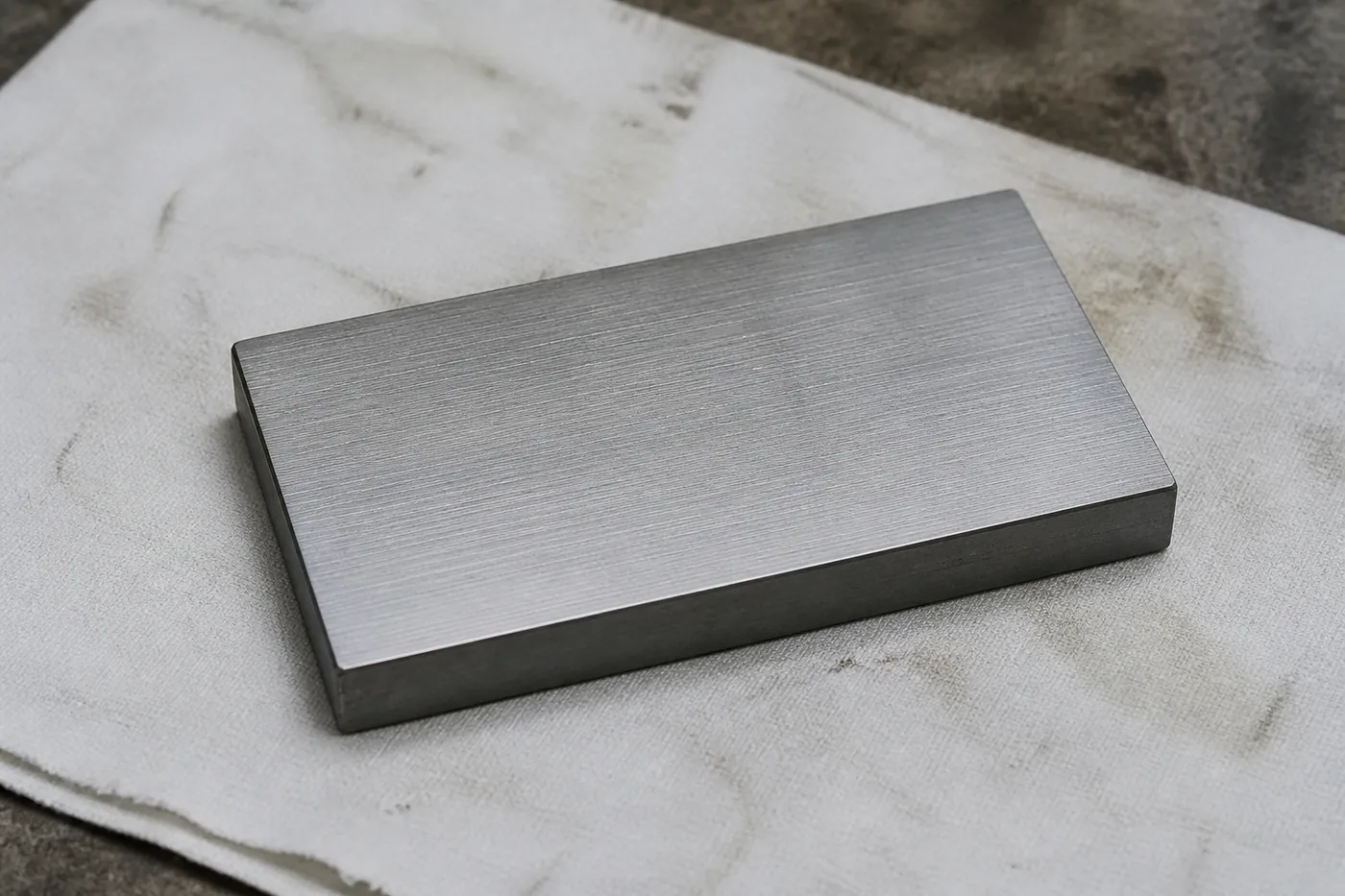
양산 표면거칠기 승인은 완성품 한 개의 Ra를 확인하는 절차가 아니라 설계 요구, 가공 조건과 검사 방법을 하나의 관리 기준으로 고정하는 과정입니다. 견적 단계에서 기능면, 파라미터, 한계값, 표준 판, 측정 방향과 확보 가능한 평가 길이를 먼저 검토해야 합니다. 짧은 면에서 필요한 traverse length가 나오지 않는다면 출하 후가 아니라 도면 검토 단계에서 대체 조건을 합의해야 합니다.
초도품 승인에는 실제 양산 소재, 공구, 치구, 프로그램과 측정기를 사용합니다. 공구 진입부·중앙부·이탈부, cavity, 얇은 벽과 chatter 가능 구간 등 기능과 위험도가 다른 위치를 포함하고 여러 부품에서 반복성을 확인합니다. 고객과 공급자의 장비가 다르면 동일 master part를 교차 측정해 필터, 팁, 방향과 데이터 처리 차이를 먼저 제거합니다.
승인 후에는 공구 수명 구간, dressing 주기, coolant 상태, spindle·fixture 이상, 측정 빈도와 반응계획을 control plan에 연결합니다. 평균 Ra만 관리하면 단일 scratch에 민감한 Rt 요구를 놓칠 수 있으므로 도면 파라미터와 공정 모니터링 파라미터를 일치시켜야 합니다.
Cp와 Cpk는 측정 시스템이 적합하고 공정이 안정된 뒤에 의미가 있습니다. 공정능력이 높더라도 Tmax가 지정된 개별 부품의 초과값을 자동으로 허용하지 않습니다. Golden sample도 외관과 가공결 비교에는 유용하지만 수치 사양과 측정 조건을 대체할 수 없습니다.
최종 승인 문서에는 도면 revision, 적용 표준, measurement operator, 측정 위치도, 초기 capability 자료, 장비 상관성 결과, 이상 발생 시 조치와 변경관리 조건을 포함하는 것이 안전합니다. 공구, 소재, 설비, 프로그램 또는 측정 방식을 바꿀 때 재승인이 필요한 범위도 함께 정해야 합니다.
English Technical Overview
Surface Roughness and Function
CNC surface roughness is not merely a visual gloss grade. It is an engineering requirement that connects component function with the manufacturing process. A part may meet its dimensional tolerances and still fail in friction, sealing, lubrication, fatigue life, plating, or coating adhesion if its surface condition is unsuitable.
Surface texture consists of roughness, the relatively fine and closely spaced irregularities; waviness, the more widely spaced undulations; and lay, the predominant direction of the surface pattern. Form components such as plane tilt, cylindrical curvature, and bending can also appear in the measured profile and must be separated before the required scale is evaluated.
Two surfaces with the same Ra can have very different structures. One may contain smooth undulations, while the other has sharp peaks and deep valleys. An average value alone cannot determine leakage risk, real contact area, lubricant retention, or wear behavior. Ra, Rz, Rt, lay, and any additional parameters must be selected for the intended function, and the lowest possible Ra is not always the best design.
Profile Separation
A traced profile contains form, waviness, roughness, and measurement noise. The ISO 21920 series uses the prefixes P, W, and R to identify the profile scale on which a parameter is evaluated.
The P-profile is the primary profile obtained after the required treatment of nominal form and short-scale components. The W-profile represents longer-spaced undulations after shorter roughness components have been limited. The R-profile represents finer surface irregularities after waviness and longer-scale components have been limited. The first letter in Ra, Rz, and Rt confirms that all three are calculated from an R-profile.
An F-operator removes nominal geometry such as a straight line or circular form. A profile S-filter limits measurement noise and excessively short-scale components, while a profile L-filter establishes the boundary between roughness and waviness. Changing the filter type or scale boundary can change the result even when the physical surface is unchanged.
The stylus tip of a contact instrument also acts as a mechanical filter. A groove narrower than the tip may not be followed completely, and a large tip may round off a sharp feature. Parameters based on different profiles, such as Pz, Wt, and Ra, are not interchangeable even when their numerical values appear similar.
Differences Between Ra, Rz, and Rt
Ra, Rz, and Rt all describe vertical surface characteristics, but their calculations and sensitivity to outliers differ. Ra is convenient for general process control, Rz is useful for monitoring section-level peaks and valleys, and Rt is appropriate when the worst height difference within the evaluation length must be limited.
| Parameter | Calculation concept | Primary use | Limitation |
|---|---|---|---|
| Ra | Arithmetic mean of the absolute profile-height deviations from the mean line over the evaluation length | General machining quality, process trending, and basic supplier comparison | An isolated scratch or peak and peak-to-valley asymmetry may be hidden by averaging. |
| Rz | Arithmetic mean of the maximum peak-to-valley heights calculated in the section lengths; five sections are used by default | Section-level irregularity and changes in peaks and valleys | It is not the single worst defect over the complete evaluation length. |
| Rt | Height difference between the highest peak and deepest valley over the complete evaluation length | Surfaces where one scratch, burr, protrusion, or deep valley may impair function | It is sensitive to contamination, outliers, location, and evaluation length. |
There is no universal fixed conversion between Ra and Rz that can be used for contractual acceptance. At the same Ra, tool geometry, feed, vibration, material tearing, and profile distribution can produce substantially different Rz and Rt values. Empirical ratios should be limited to preliminary estimates, and the required parameter must be measured directly.
Sealing, sliding, and lubricant-retaining surfaces may also require Rp, Rv, Rsk, RSm, Rmr, or Rk, Rpk, and Rvk parameters together with the specified lay. Legacy Rmax and Rz1max designations and the current Rzx(l) parameter must not be assumed to mean the same thing as Rt; the applicable drawing standard must be checked.
Filters and Evaluation Length
A roughness result depends on the scale range classified as roughness. The cutoff wavelength λc used on earlier drawings has been generalized in ISO 21920 as the profile L-filter nesting index Nic. For a linear Gaussian filter, Nic can be related numerically to the former λc, while the nesting-index concept also covers non-linear filters.
The evaluation length le is the length used to calculate the parameter. The section length lsc applies to section-based parameters such as Rz. The actual stylus traverse can be longer than le because approach distances and filter end effects must be accommodated.
| Item | Sc1 | Sc2 | Sc3 | Sc4 | Sc5 |
|---|---|---|---|---|---|
| Ra upper limit U | ≤ 0.02 µm | > 0.02–0.1 µm | > 0.1–2 µm | > 2–10 µm | > 10 µm |
| Rz upper limit U | ≤ 0.16 µm | > 0.16–0.8 µm | > 0.8–16 µm | > 16–80 µm | > 80 µm |
| Rt upper limit U | ≤ 0.26 µm | > 0.26–1.3 µm | > 1.3–26 µm | > 26–130 µm | > 130 µm |
| Nic | 0.08 mm | 0.25 mm | 0.8 mm | 2.5 mm | 8 mm |
| le | 0.4 mm | 1.25 mm | 4 mm | 12.5 mm | 40 mm |
| Nis | 2.5 µm | 2.5 µm | 2.5 µm | 8 µm | 25 µm |
| lsc / nsc | 0.08 mm / 5 | 0.25 mm / 5 | 0.8 mm / 5 | 2.5 mm / 5 | 8 mm / 5 |
The table applies when an upper tolerance limit U is specified for parameters such as Ra, Rz, or Rt and no separate measurement settings are given. Lower and bilateral tolerances follow their own selection rules. An explicitly stated filter or setting class takes precedence over the defaults.
For example, a simple ISO 21920 upper limit of Ra 0.8 µm falls within Sc3, giving a default Nic of 0.8 mm and le of 4 mm. An upper limit of Ra 3.2 µm falls within Sc4, giving a default Nic of 2.5 mm and le of 12.5 mm. Applying a customary 0.8 mm cutoff to every machined surface can therefore produce results that do not represent the drawing requirement.
Measurement Direction and Location
Profile surface-texture measurement is direction-sensitive. Unless otherwise specified, a stylus is generally traversed perpendicular to the predominant lay so that a large height variation is evaluated. A profile direction or lay direction stated on the drawing takes precedence over this general practice.
On a turned outside diameter, a representative trace may cross the helical feed marks. On a milled surface, the trace may cross the toolpath or scallop pattern. Complex toolpaths, crossed lay, and five-axis freeform surfaces may not be represented adequately by Ra from one direction. Multiple traces in functional directions or ISO 25178 areal parameters such as Sa may be more appropriate.
Tool entry and exit zones, thin walls, corners, clamping regions, and areas where chatter develops may differ from the center of a surface. Functionally critical locations and positions where maximum values are expected should be defined in the drawing or inspection plan.
Contact and optical results are not automatically equivalent. Stylus-tip radius, optical response to slope and reflectivity, data interpolation, and filter implementation can all differ. The acquisition method and its settings must be controlled for production approval, and the line parameter Ra must not be treated as interchangeable with the areal parameter Sa.
Milling, Turning, and Grinding Finish
Process-based roughness ranges are useful for early manufacturability reviews and quotations, but they are not guaranteed acceptance values. Material, hardness, machine rigidity, tool overhang, runout, edge wear, feed, depth of cut, coolant, fixturing, and vibration determine the actual result.
| Process | Conditional reference range | Major variables | Design and inspection caution |
|---|---|---|---|
| Turning | Ra of approximately 0.8–3.2 µm is common for a controlled finish pass; stable conditions and wiper geometry may produce lower values. | Feed, nose radius, insert geometry, built-up edge, runout, and chatter | Theoretical feed-mark height is not actual Ra, and a large nose radius may worsen finish if it induces vibration. |
| Milling | Ra of approximately 0.8–3.2 µm is common in controlled finishing, with a wide range caused by toolpath and geometry. | Feed per tooth, step-over, cutter diameter, insert-height variation, tool runout, and cutting direction | Face milling and ball-end freeform machining can have different scallop structures and measurement directions at the same Ra target. |
| Precision grinding | Ra of approximately 0.1–0.8 µm or lower may be achievable, while coarse grinding may be higher. | Wheel grit and grade, dressing, wheel balance, feed, coolant, and thermal damage | A low Ra value does not demonstrate the absence of grinding burn or tensile residual stress. |
| Honing and superfinishing | Cylinder-honing applications may use Ra of approximately 0.2–1 µm, while specialized superfinishing can achieve below 0.1 µm. | Stone grit, pressure, crosshatch angle, number of stages, and initial surface condition | Lubricant-retaining valleys and plateau structure may be required, so the lowest possible Ra is not always the objective. |
| EDM | No single range is representative; roughing and multi-pass skim or finishing conditions differ substantially. | Discharge energy, pulse settings, electrode or wire, dielectric, and number of skim passes | Ultra-fine results from specialized equipment must not be treated as general EDM production capability. |
The ideal cusp height in turning increases with the square of feed and decreases as nose radius becomes larger, but this relationship describes only the geometric toolpath. It does not account for material flow, tool wear, built-up edge, vibration, or machine error and must not be treated as a direct calculation of inspected Ra, Rz, or Rt.
Milling requires evaluation of toolpath periodicity, step-over marks, and local mismatch in addition to average Ra. In grinding, wheel dressing and thermal control are critical, and an extremely low Ra does not confirm that grinding burn or surface-layer damage is absent.
Drawing Callouts and Standards
ISO 21920-1 defines the indication of profile surface texture, ISO 21920-2 defines terms and parameters, and ISO 21920-3 defines specification operators and default measurement settings. New drawings should identify the applicable standard and edition in the title block or technical specification.
Parameters with defined defaults, including Ra, Rz, and Rt, can use a minimal indication consisting of the graphical symbol, parameter designation, and tolerance limit. For a minimal Ra 0.8 µm indication, unspecified elements follow the ISO 21920-3 defaults for an upper limit, the Tmax acceptance rule, and the applicable setting class.
The graphical symbols distinguish any manufacturing process permitted, material removal required, and material removal not permitted. Function-critical surfaces may additionally specify U or L tolerance type, bilateral limits, Tmax, T16%, or Tmed acceptance, Nic and Nis, le or lsc/nsc, profile direction, manufacturing method, lay, and acquisition method.
ASME drawings use the surface-texture definitions of ASME B46.1 together with the graphical-symbol system of ASME Y14.36. ISO default measurement settings must not be applied automatically to an ASME drawing, or vice versa. Legacy indications using only a number, multiple triangles, or an N grade require confirmation of the drawing standard and company convention.
ISO Standards Transition
ISO 21920-1/-2/-3:2021 remains the current published profile surface-texture series as of August 2026. The series took over the respective roles of ISO 1302:2002, ISO 4287:1997, and ISO 4288:1996. Edition 2 committee drafts considered in 2026 have not yet become published standards and must not be applied as finalized requirements.
The former ISO 4288 approach distinguished periodic and nonperiodic profiles and selected a cutoff from an estimated or measured Ra, Rz, or RSm. ISO 21920 removes that distinction and derives default measurement settings primarily from the tolerance and setting class specified by design. The specification now determines the measurement operator rather than allowing an inspector to select a favorable cutoff after preliminary measurement.
The acceptance rule has also changed. Under the former ISO 1302 and ISO 4288 framework, the default without an additional indication was the 16% rule. ISO 21920 defaults to the maximum rule, Tmax. T16% does not mean that the tolerance limit may be increased by 16%; it is an explicitly stated rule that permits a limited proportion of measured values to exceed the limit under its defined procedure. Tmed is a separate rule based on the median of measured values.
Under the newer framework, surface imperfections are included by default unless otherwise excluded. External contamination such as dust or residual cutting fluid must still be removed before measurement. A legacy drawing does not acquire new defaults merely because its cited standard has been withdrawn; the standard and publication year stated on the drawing remain controlling until the specification is revised.
Inspection Repeatability
Matching only the parameter name is not enough for different inspectors to obtain comparable results. The standard and edition, profile type, filters, Nic and Nis, le, lsc/nsc, stylus-tip radius, measurement speed, direction, location, and form-removal condition must also be aligned.
Cutting fluid, dust, and loose particles should be removed before measurement, and the component and instrument should be thermally stable. Stylus-tip wear or damage, skid or datum configuration, instrument leveling, and calibration status must also be checked. A roughness reference specimen is useful for confirming instrument condition, but it cannot reproduce every effect of actual component curvature, material, lay, and access.
Repeated inspection is generally more informative when adjacent traces or multiple components are measured at agreed functional locations rather than tracing exactly the same line repeatedly. A contact stylus may alter a soft surface. Tmed requires at least three measured values, while an average within tolerance cannot justify ignoring an individual exceedance when Tmax applies.
An inspection report should record the result and unit together with the standard and edition, parameter and profile, filters and lengths, probe or optical method, measurement direction and location, number of repetitions, acceptance rule, and instrument identification. A value close to the limit should not be accepted solely by rounding; measurement uncertainty and the agreed decision rule should be considered.
Production Approval
Production surface-texture approval is not merely a check of Ra on one completed part. It establishes a common control basis linking the design requirement, machining conditions, and inspection method. The functional surface, parameter, limit, standard edition, measurement direction, and available evaluation length should be reviewed during quotation. If a short surface cannot accommodate the required traverse, an alternative must be agreed during drawing review rather than after shipment.
First-article approval should use the actual production material, tooling, fixture, program, and measuring system. It should include functionally different and high-risk locations such as tool entry, center, exit, cavities, thin walls, and chatter-prone regions, with repeat measurements across multiple components. When customer and supplier equipment differ, a common master part should be cross-measured to resolve filter, tip, direction, and data-processing differences.
After approval, tool-life intervals, dressing frequency, coolant condition, spindle or fixture abnormalities, inspection frequency, and reaction plans should be connected to the control plan. Monitoring only average Ra may miss an Rt requirement that is sensitive to a single scratch, so process-monitoring parameters should remain aligned with the drawing parameters.
Process capability indices such as Cp and Cpk become meaningful only after the measurement system is adequate and the process is stable. High process capability does not automatically permit an individual exceedance on a component specified with Tmax. A golden sample is useful for visual texture and lay comparison, but it does not replace numerical requirements and measurement settings.
Final approval records should include the drawing revision, applicable standard, measurement operator, location map, initial capability data, equipment-correlation results, abnormal-condition response, and change-control criteria. Conditions requiring reapproval after a change in tooling, material, equipment, program, or measurement method should also be defined.
추가 정보
검색엔진용 요약
CNC 표면거칠기의 Ra·Rz·Rt 차이와 P·W·R 프로파일, ISO 21920 도면 기호와 기본 측정 조건을 정리합니다. 컷오프·평가 길이, 측정 방향, 밀링·선삭·연삭 특성과 양산 승인 기준까지 연결해 설명합니다.
핵심 포인트 정리
- Ra는 평균 높이, Rz는 구간별 최대 높이의 평균, Rt는 평가 길이 전체의 최대 높이차입니다.
- 동일한 Ra라도 peak, valley, 가공결과 기능 성능은 다를 수 있습니다.
- 측정값 비교에는 profile, 필터, Nic·Nis, 평가 길이, 팁, 방향과 위치가 모두 같아야 합니다.
- ISO 21920은 지정 tolerance에서 기본 setting class를 결정하며 periodic·nonperiodic 구분을 사용하지 않습니다.
- ISO 21920의 기본 acceptance rule은 Tmax이고 T16%는 명시해야 합니다.
- 공정별 조도는 조건부 참고값이며 양산 승인은 측정 operator, 위치도, 장비 상관성과 변경관리까지 고정해야 합니다.
FAQ
Ra 0.8이면 cutoff도 항상 0.8 mm입니까?
현행 ISO 21920에서 Ra 0.8 µm가 단순 상한 공차이고 별도 조건이 없다면 Sc3 기본값인 Nic 0.8 mm와 le 4 mm를 사용합니다. 구 표준, ASME 도면, 양측 공차 또는 별도 setting class가 있으면 조건이 달라집니다.
Ra 값을 Rz로 환산할 수 있습니까?
계약 판정에 사용할 수 있는 보편적인 환산식은 없습니다. 동일 Ra라도 가공 방식과 profile 형상에 따라 Rz와 Rt가 달라지므로 필요한 파라미터를 직접 측정해야 합니다.
같은 부품을 측정했는데 장비마다 값이 다른 이유는 무엇입니까?
필터와 평가 길이, 스타일러스 팁 반경, 측정 방향·위치, form 제거, 접촉식·광학식 차이가 주요 원인입니다. 장비 이상을 판단하기 전에 전체 measurement operator를 비교해야 합니다.
표면거칠기는 어느 방향으로 측정합니까?
도면 지정 방향이 최우선이며 별도 지시가 없으면 일반적으로 주된 가공결에 직각으로 측정합니다. 복합 가공결이나 자유곡면은 여러 방향의 trace 또는 면적 측정을 검토합니다.
Ra는 낮을수록 항상 좋습니까?
그렇지 않습니다. 윤활 유지에는 valley가 필요할 수 있고 접착과 도장에는 적절한 미세 요철이 도움이 될 수 있습니다. 기능보다 과도하게 낮은 Ra는 가공비만 높이고 필요한 표면 구조를 제거할 수 있습니다.
양산에서는 몇 번 측정해야 합니까?
모든 부품에 공통인 단일 횟수는 없습니다. 도면의 acceptance rule, 표면 크기, 공정 산포와 위험도에 따라 위치 수와 부품 수를 정합니다. Tmed는 최소 세 개 이상의 값이 필요하며 Tmax 요구는 평균값만으로 판정할 수 없습니다.
관련 주제 확장 설명
치수 공차와 표면거칠기
치수 공차는 형상의 크기와 위치가 허용 구간에 있는지를 관리하고 표면거칠기는 표면의 미세 높이 구조를 관리합니다. 정밀한 끼워맞춤에서도 거친 peak가 초기 마모와 실제 접촉면적에 영향을 줄 수 있으므로 두 요구사항을 별도로 지정해야 합니다.
2D Ra와 3D Sa
Ra는 한 개의 선형 R-profile을 평가하지만 Sa는 일정 면적의 높이 편차를 평가합니다. 가공결이 일정한 선삭면은 profile 방식이 효율적일 수 있고 방향성이 복잡한 방전·블라스팅·자유곡면은 면적 평가가 더 많은 정보를 제공할 수 있습니다. 평가 차원이 다르므로 같은 숫자라고 동등한 사양이 아닙니다.
기능성 파라미터
실링면은 깊은 valley와 lay, 미끄럼면은 plateau와 윤활 유지 구조, 피로 부품은 날카로운 valley와 표면 손상을 중요하게 볼 수 있습니다. Ra만으로 기능을 설명하기 어려우면 Rp, Rv, Rsk, RSm, Rmr, Rk·Rpk·Rvk 또는 Rt를 목적에 맞게 추가합니다.
내부 링크
표면거칠기는 치수·형상 정확도와 별도로 관리해야 하므로 CNC 가공 공차와 정밀도를 함께 검토하는 것이 좋습니다. 선삭과 밀링의 공구 경로 및 적용 차이는 CNC 선삭·밀링 부품, 보어와 정밀 홀의 표면 요구는 CNC 드릴링과 정밀 홀 가공에서 확장할 수 있습니다.
부싱의 내·외경과 미끄럼면 적용은 롤러·부싱 가공 공정, 머시닝센터의 공정 구성은 MCT 가공에서 확인할 수 있습니다. 소재, 수량, 도면 공차와 필요한 표면거칠기를 기준으로 제작 가능성을 검토하려면 가공 문의를 이용할 수 있습니다.