CNC 선삭 밀링 복합가공 부품의 기능면 품질 기준
CNC 선삭 밀링 복합가공 부품은 원통축을 만드는 선삭, 평면과 홈을 만드는 밀링, 체결축을 만드는 드릴링·탭·나사 가공이 한 부품 안에서 만나는 정밀 부품군입니다. 같은 치수 공차를 만족해도 기준축과 기준면의 선택이 잘못되면 조립 위치, 회전 안정성, 체결력 분포, 간격 반복성이 서로 다르게 나타날 수 있습니다.
품질 판단의 출발점은 “어느 면이 실제 기능을 결정하는가”입니다. 내경 보어가 상대 축을 안내한다면 내경이 기준이 되어야 하고, 플랜지면이 체결력을 받는다면 평탄도와 직각도가 핵심 기준이 됩니다. U홈과 핀홀이 운동축을 만들면 홀 위치도와 양쪽 귀의 평행도가 치수보다 먼저 검토되어야 합니다.
복합가공 부품은 공정이 늘어날수록 기준 전환의 위험도 함께 커집니다. 한 번의 척킹에서 끝나는 단순 선삭품과 달리, 선삭 기준축에서 밀링 기준면으로 넘어가고 다시 나사·홀·카운터보어로 이어지는 과정에서 오차가 누적될 수 있습니다. 따라서 도면, 공정 순서, 검사 기준은 별도 문서가 아니라 하나의 기능면 체계로 연결되어야 합니다.
아래 내용은 테이퍼 슬리브, 널링 샤프트, 플랜지 링, 테이퍼 보스, 숄더볼트형 샤프트, 스페이서 링, 플랜지 부싱, 클레비스 조인트, 육각 스탠드오프를 기준으로 기준면 설정, 기능면 품질, 표면 상태, 버 관리, 검사 흐름을 체계적으로 정리한 기술 해설입니다.
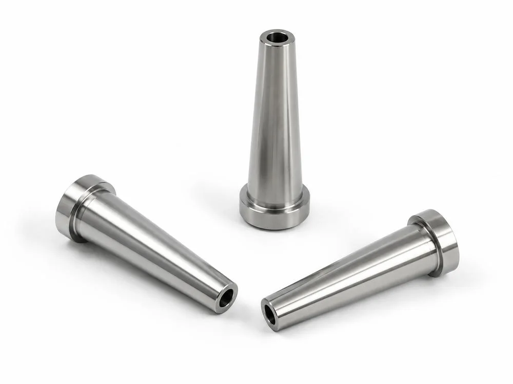
테이퍼 보어 슬리브의 내경 기준과 외경 정렬
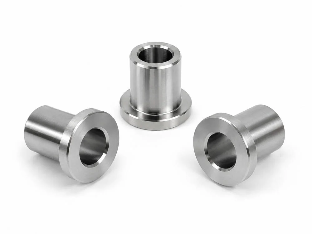
테이퍼 보어 슬리브는 외경 테이퍼, 관통 내경, 어깨부 단차, 입구 모따기가 한 축 위에 놓이는 구조입니다. 기능은 삽입 안내, 축방향 위치 결정, 유량 통로, 하우징 안착, 상대 부품의 중심 보정까지 넓게 확장될 수 있습니다. 이때 외관상 원뿔 형상이 깨끗한지보다 내경 보어와 외경 테이퍼가 같은 회전 기준축을 공유하는지가 더 중요합니다.
테이퍼면은 접촉 면적을 분산시키는 기능면입니다. 테이퍼 각도만 맞고 축이 흔들리면 상대 부품은 전체 면으로 닿지 않고 한쪽 가장자리부터 먼저 닿습니다. 이런 상태에서는 삽입 저항, 편마모, 체결 후 흔들림, 국부적인 접촉 압력 증가가 나타날 수 있습니다.
내경이 실제 가이드 기준이라면 검사도 내경 중심축을 기준으로 재구성되어야 합니다. 외경 단차의 동심도, 테이퍼면의 런아웃, 어깨부의 직각도, 내경 조도, 입구 모따기 상태를 같은 기준축에서 확인해야 합니다. 내경 보링과 외경 선삭이 다른 셋업에서 나뉘면 재척킹 흔들림과 기준 전환 오차까지 품질 변수에 포함됩니다.
테이퍼 슬리브류에서 품질 기준은 치수 목록을 늘리는 방식보다 기능 순서를 정하는 방식이 더 정확합니다. 먼저 가이드 축을 정하고, 그 다음 접촉 테이퍼면, 안착 어깨부, 삽입 모서리 순으로 검사 우선순위를 잡아야 조립성 판단이 흔들리지 않습니다.
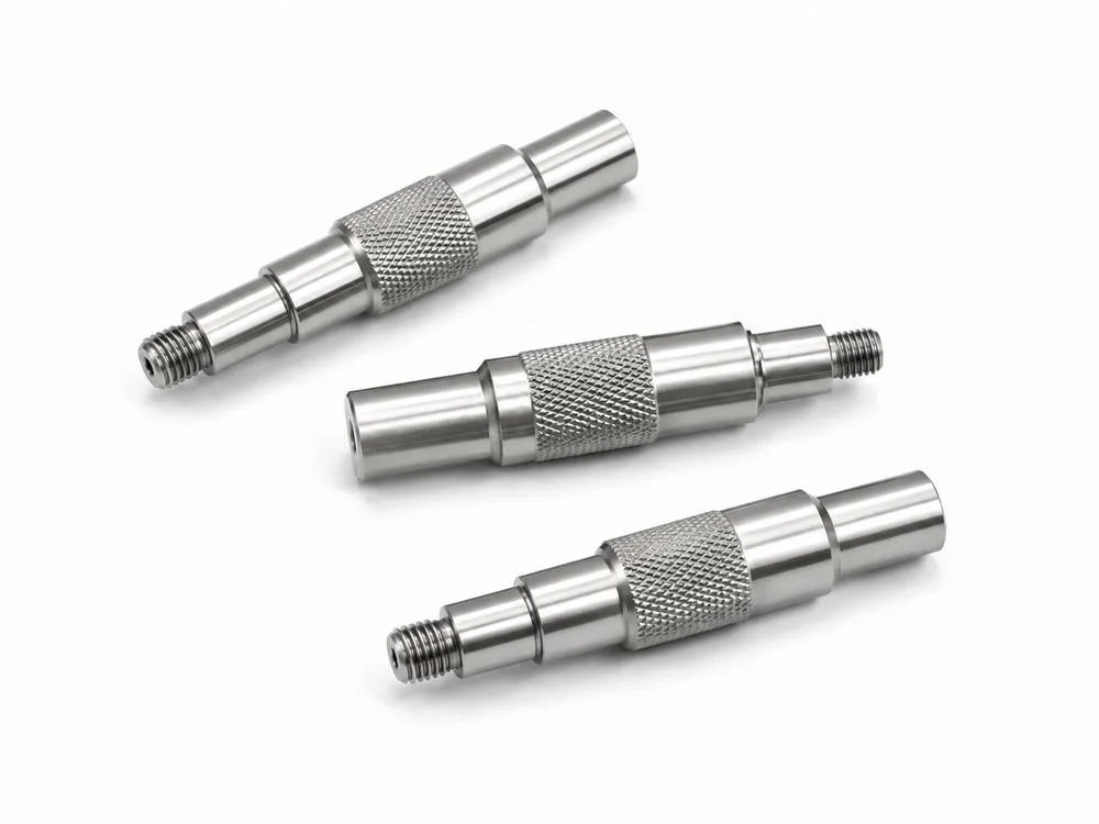
널링 샤프트의 그립 영역과 외나사 체결 영역
널링 샤프트는 그립, 압입 유지, 미끄럼 방지, 수동 조작, 토크 전달을 위해 표면에 의도적인 요철을 만드는 부품입니다. 중앙 널링 영역은 마찰을 높이는 기능면이지만 동시에 외경을 변화시키고 표면층에 국부 변형을 남길 수 있습니다. 따라서 널링은 장식 패턴이 아니라 외경 변화와 접촉 압력을 동반하는 가공 영역으로 보아야 합니다.
외나사가 함께 있는 단차 샤프트는 그립 영역과 체결 영역의 품질 언어가 다릅니다. 널링부는 패턴 균일성, 피치, 산 높이, 눌림, 외경 팽창, 끝단 말림을 보아야 하고, 외나사부는 피치, 유효 길이, 시작부 모따기, 끝단 버, 게이지 통과성을 보아야 합니다. 두 영역은 기능이 다르지만 같은 중심축을 공유하기 때문에 런아웃 관리가 필요합니다.
널링이 압입 유지에 쓰일 경우에는 상대 재료의 변형 여유와 삽입 방향이 품질 기준이 됩니다. 과한 널링은 조립력을 높일 수 있지만 상대 부품을 긁거나 균열을 만들 수 있으며, 부족한 널링은 반복 사용에서 풀림과 헛돌림을 만들 수 있습니다. 표면 경화와 미세 균열 가능성도 함께 검토해야 합니다.
나사산과 널링이 같은 부품에 놓이면 공정 순서도 중요합니다. 나사 가공 후 널링을 강하게 넣으면 나사 기준축 주변에 미세 변형이 남을 수 있고, 널링 후 마감 선삭을 하면 패턴의 기능 깊이가 달라질 수 있습니다. 품질 기준은 외관, 치수, 체결성, 표면 상태를 분리하지 않고 하나의 기능면 조합으로 판단해야 합니다.
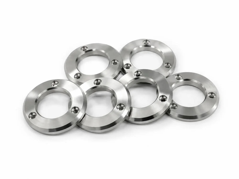
카운터보어 플랜지 링의 체결면과 홀 위치도
카운터보어 플랜지 링은 중심 내경, 외경, 볼트 홀 패턴, 카운터보어 깊이, 상하면 평탄도가 동시에 작동하는 원형 체결 부품입니다. 볼트 머리는 카운터보어 바닥면에 안착하고, 링 자체는 중심 내경이나 외경을 기준으로 상대 부품에 위치합니다. 따라서 홀 하나의 좌표보다 볼트 피치 원, 중심 기준, 체결면이 같은 기준계 안에 있는지가 더 중요합니다.
체결면이 평탄하지 않으면 볼트가 균일하게 안착되지 않습니다. 한쪽 모서리만 먼저 닿으면 토크가 체결력으로 안정적으로 변환되지 않고, 반복 진동에서는 접촉면 눌림과 풀림 가능성이 커집니다. 카운터보어 깊이, 바닥면 조도, 모서리 버, 홀 입구 모따기는 모두 체결력 전달에 연결됩니다.
플랜지 링의 기능 기준은 용도에 따라 달라집니다. 중심 내경이 베어링이나 샤프트를 안내하면 내경 기준이 우선이고, 외경이 하우징에 맞물리면 외경 기준이 우선입니다. 볼트 패턴이 위치 결정을 담당하면 홀 위치도와 피치 원의 관계가 중요해집니다. 도면과 검사 계획은 이 기준 우선순위를 명확히 반영해야 합니다.
실무적으로는 중심 기준축을 잡은 뒤 플랜지 상하면의 평행도, 카운터보어 깊이, 홀 위치도, 바닥면 조도, 홀 주변 버를 같은 검사 흐름 안에서 확인하는 것이 안정적입니다. 특히 얇은 링은 체결 중 휨이 생기기 쉬우므로 자유 상태의 평탄도와 체결 상태의 접촉 안정성을 구분해 해석해야 합니다.
CNC 복합가공 부품 형상별 기능면 품질 매트릭스
선삭 중심축, 밀링 기준면, 나사 체결축, 핀홀 위치도, 내외경 동심도를 한 번에 비교하기 위한 기술 판단 표입니다. 각 항목 위에 커서를 올리면 검토 이유가 표시됩니다.
| 부품 형상 | 주요 기능면 | 공정 제어점 | 검사 기준 | 품질 리스크 | 설계 판단 |
|---|---|---|---|---|---|
| 테이퍼 보어 슬리브 | 내경, 테이퍼 외경, 어깨부 | 테이퍼 각도, 내경 보링, 기준축 정렬 | 동심도, 각도, 내경 조도, 플랜지 직각도 | 편심, 삽입 불량, 접촉면 흔들림 | 기준축 우선 지정 |
| 널링 단차 샤프트 | 널링부, 단차 외경, 외나사 | 널링 피치, 외경 단차, 나사 절삭 | 널링 깊이, 나사 게이지, 런아웃 | 외경 팽창, 체결 불량, 표면 손상 | 그립부와 체결부 분리 관리 |
| 카운터보어 플랜지 링 | 플랜지면, 내경, 카운터보어 | 면삭, 홀 위치도, 카운터보어 깊이 | 평탄도, 위치도, 깊이, 모따기 | 체결 들뜸, 볼트 간섭, 누설 | 체결면 기준 우선 |
| 클레비스 조인트 | U홈, 핀홀, 나사부 | U홈 가공, 핀홀 드릴링, 나사 가공 | 핀홀 동축도, 평행도, 홈 폭 | 핀 삽입 불량, 편마모, 하중 편심 | 핀축과 체결축 관계 지정 |
| 육각 스탠드오프 | 육각면, 암나사, 외나사 | 탭 깊이, 외나사 길이, 육각 밀링 | 나사 게이지, 체결면 직각도, 높이 | 체결 깊이 부족, 높이 편차, 풀림 | 조립 높이 반복성 관리 |
테이퍼 보어 슬리브
기능면: 내경, 테이퍼 외경, 어깨부입니다.
검사: 동심도, 테이퍼 각도, 내경 조도, 플랜지 직각도입니다.
기준축 우선 지정널링 단차 샤프트
기능면: 널링부, 단차 외경, 외나사입니다.
검사: 널링 깊이, 나사 게이지, 런아웃입니다.
그립부와 체결부 분리 관리카운터보어 플랜지 링
기능면: 플랜지면, 내경, 카운터보어입니다.
검사: 평탄도, 위치도, 깊이, 모따기입니다.
체결면 기준 우선클레비스 조인트
기능면: U홈, 핀홀, 나사부입니다.
검사: 핀홀 동축도, 평행도, 홈 폭입니다.
핀축과 체결축 관계 지정육각 스탠드오프
기능면: 육각면, 암나사, 외나사입니다.
검사: 나사 게이지, 체결면 직각도, 높이입니다.
조립 높이 반복성 관리기준면과 기능면의 연결 순서
선삭 기준축, 밀링 기준면, 나사 체결축, 핀홀 위치도, 표면 조도와 버 방향은 독립 항목처럼 보이지만 실제 조립에서는 하나의 기능면 체계로 작동합니다. 기준을 먼저 고정하고, 그 기준에서 실제 기능면까지 이어지는 검사 흐름을 같은 좌표계 안에서 묶어야 합니다.
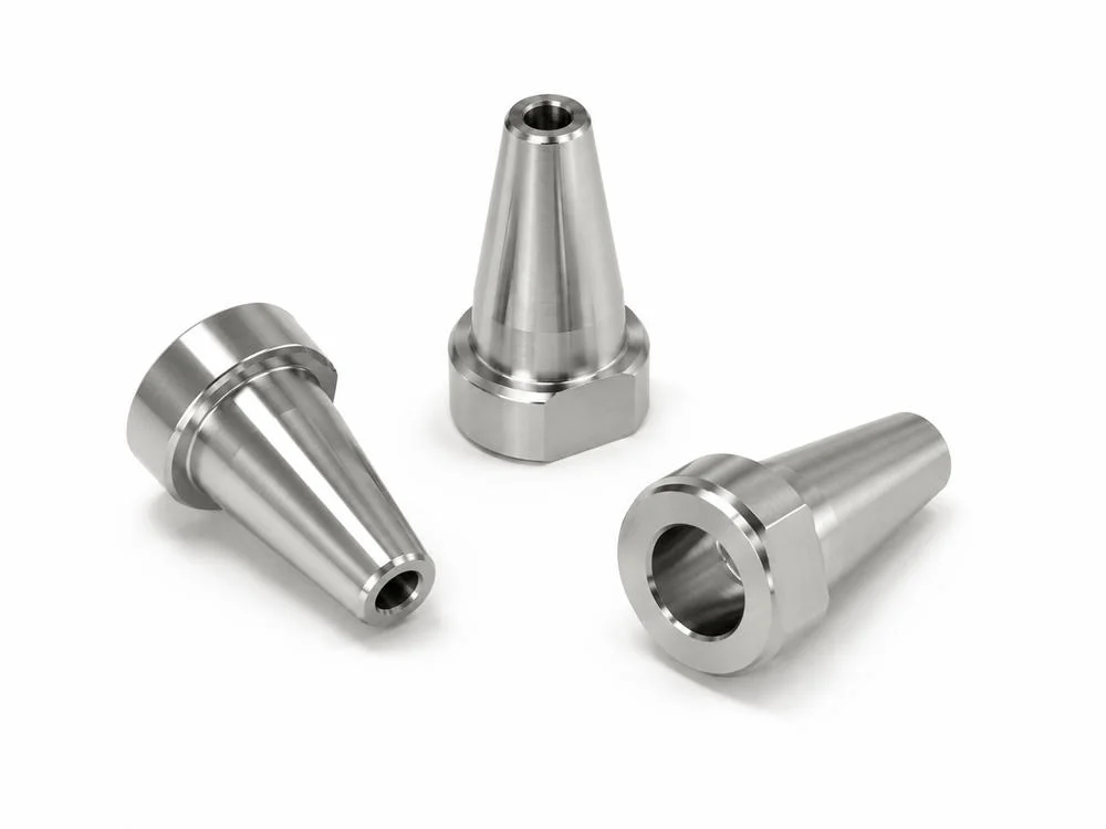
테이퍼 보스 부품의 육각 기준면과 관통 내경
테이퍼 보스 부품은 선삭으로 만든 원통·테이퍼 기준축과 밀링으로 만든 육각 또는 평면 기준면이 결합된 형상입니다. 원통부는 회전 대칭 품질을 요구하고, 육각부는 공구 체결이나 회전 방지 기능을 담당합니다. 한 부품 안에서 기준축과 기준면이 동시에 요구되기 때문에 셋업 전환 관리가 품질의 핵심이 됩니다.
관통 내경이 상대 축을 안내하면 내경 중심축은 가장 중요한 기능 기준이 됩니다. 외경 테이퍼와 육각 평면이 보기 좋게 가공되어도 내경 중심이 틀어지면 삽입 후 하중이 한쪽으로 몰리고, 체결면이 부분 접촉으로 변할 수 있습니다. 내경 보어는 치수뿐 아니라 원형도, 원통도, 표면 조도, 입구 모따기를 함께 확인해야 합니다.
육각 기준면은 렌치 체결, 방향 지정, 회전 방지에 관여합니다. 육각면의 대변 거리만 맞추는 것으로는 충분하지 않고, 기준축에 대한 위치 관계와 모서리 품질까지 확인해야 합니다. 밀링 버가 남으면 공구 체결성이 떨어지고 상대 부품의 안착면을 손상시킬 수 있습니다.
테이퍼 보스류의 검사 순서는 내경 기준축, 테이퍼면, 어깨부 직각도, 육각 평면, 모서리 상태 순으로 구성하는 것이 합리적입니다. 이 순서를 정하면 치수 검사와 기능 검사가 분리되지 않고 조립 조건에 가까운 품질 판단으로 이어집니다.
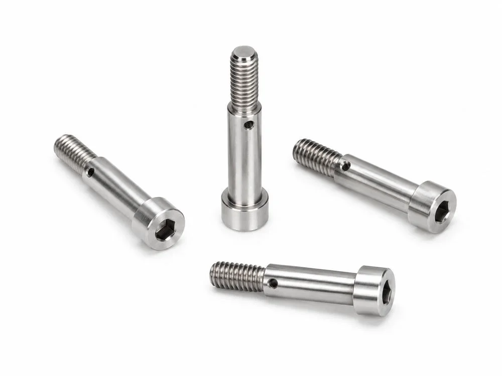
숄더볼트형 정밀 체결 샤프트의 나사산과 렌치홈
숄더볼트형 정밀 체결 샤프트는 머리부, 렌치홈, 어깨부, 몸통 외경, 외나사가 하나의 축으로 연결되는 부품입니다. 일반 볼트처럼 보일 수 있지만 정밀 가공품에서는 나사산만이 기능면이 아닙니다. 머리 하부의 체결면, 숄더 외경, 어깨부 직각도, 렌치홈, 나사 시작부가 모두 조립 품질에 영향을 줍니다.
숄더 외경이 위치 결정 역할을 하면 나사산보다 외경과 어깨부가 먼저 기준이 됩니다. 숄더부가 상대 구멍에 들어가 위치를 잡고 나사산은 체결만 담당하는 구조에서는 몸통 외경의 치수 안정성, 원통도, 런아웃, 어깨부 직각도가 핵심입니다. 반대로 체결력이 주요 기능이면 나사 유효 길이, 피치 상태, 체결면 조도가 우선됩니다.
렌치홈은 토크를 전달하는 기능면입니다. 홈 깊이, 모서리 R, 버, 육각 형상 편차가 맞지 않으면 체결 공구가 미끄러지거나 홈 모서리가 손상될 수 있습니다. 특히 소형 정밀 체결품에서는 렌치홈의 작은 버도 조립 공구 손상과 체결 토크 편차를 만들 수 있습니다.
나사산 검사는 게이지 통과 여부에서 끝나지 않습니다. 시작부 모따기, 끝단 버, 골과 산의 표면 눌림, 나사산과 숄더 축의 동축 관계, 체결면과 축의 직각도를 함께 봐야 합니다. 숄더볼트형 부품은 체결품이면서 위치 결정품이기 때문에 두 품질 기준을 분리하지 않는 것이 중요합니다.
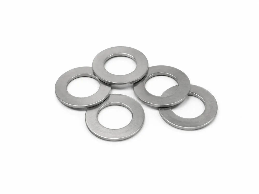
정밀 와셔와 스페이서 링의 평탄도와 두께 공차
정밀 와셔와 스페이서 링은 단순 원형 부품이 아니라 체결 압력 분산, 간격 유지, 축방향 위치 결정, 마찰면 보호에 쓰이는 기능 부품입니다. 얇고 평평한 형상일수록 두께 공차, 양면 평행도, 평탄도, 내외경 버가 조립 품질에 직접 연결됩니다.
스페이서 기능에서는 평균 두께보다 반복 높이가 중요합니다. 한 지점의 두께만 맞아도 양면이 평행하지 않으면 조립 후 상대 부품이 기울어질 수 있습니다. 여러 개의 스페이서가 동시에 사용되는 구조에서는 개별 부품의 편차가 전체 조립면의 뒤틀림으로 확장됩니다.
내경 버는 샤프트나 볼트에 간섭하고, 외경 버는 상대면을 긁거나 간격을 바꿀 수 있습니다. 모따기를 크게 주면 조립성은 좋아질 수 있지만 실제 접촉면적이 줄어드는 문제가 생길 수 있습니다. 따라서 모따기 폭과 버 제거는 기능면의 접촉 조건에 맞춰 관리되어야 합니다.
정밀 와셔류는 평탄도, 평행도, 표면 조도, 내외경 동심도, 모서리 품질을 한 번에 확인해야 합니다. 특히 체결 압력을 받는 면은 Ra 수치만으로 충분하지 않고, 국부적인 피크와 눌림 자국, 방향성 있는 가공흔까지 검토해야 안정적인 체결 압력 분포를 얻을 수 있습니다.
플랜지 부싱 슬리브의 내외경 동심도와 어깨부 기준면
플랜지 부싱과 단차 슬리브는 내경으로 축을 안내하고 외경 또는 플랜지면으로 하우징에 위치를 잡는 구조가 많습니다. 내경과 외경이 서로 다른 중심을 가지면 조립은 가능하더라도 회전 흔들림, 편마모, 소음, 씰링 불량, 윤활막 불안정이 발생할 수 있습니다.
부싱류에서 내경은 실제 운동 기준이 되는 경우가 많습니다. 내경 치수, 원통도, 조도, 입구 모따기, 버 제거가 모두 축의 삽입성과 회전 안정성에 영향을 줍니다. 외경은 하우징과의 압입 또는 위치 결정을 담당하므로 내경 기준축에 대한 동심도와 외경 공차가 함께 관리되어야 합니다.
플랜지면과 어깨부는 축방향 위치를 결정합니다. 이 면이 기준면에 안정적으로 닿아야 조립 높이와 위치가 반복됩니다. 어깨부 직각도가 틀어지거나 플랜지면에 가공흔과 버가 남으면 부품은 미세하게 기울고, 내경을 통과하는 축은 예상과 다른 접촉 상태를 갖게 됩니다.
검사에서는 내경 기준축을 세운 뒤 외경 런아웃, 플랜지면 직각도, 단차 높이, 모따기 상태, 표면 조도를 연결해서 보아야 합니다. 윤활, 회전, 압입 조건이 있는 부싱은 표면 조도와 모서리 품질이 수명과 직결되므로 별도 기능면 기준으로 다루는 것이 적절합니다.
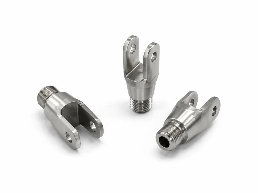
클레비스 조인트 부품의 U홈과 핀홀 정렬 기준
클레비스 조인트는 선삭으로 만든 원통부와 나사부, 밀링으로 만든 U홈, 드릴링으로 만든 핀홀이 결합된 대표적인 CNC 복합가공 부품입니다. 이 부품의 기능은 단순 체결이 아니라 핀을 중심으로 한 회전 운동과 하중 전달입니다. 따라서 U홈의 양쪽 귀, 핀홀, 나사축, 어깨부 기준면이 하나의 운동 구조로 정렬되어야 합니다.
핀홀 위치가 조금만 틀어져도 핀 삽입이 뻑뻑해지고 한쪽 귀에 하중이 집중될 수 있습니다. 두 귀의 홀 축이 일치하지 않으면 핀은 회전축이 아니라 강제 정렬 부품처럼 작동하고, 장기적으로 홀 마모와 유격 증가가 빨라질 수 있습니다. U홈 폭, 양쪽 귀의 평행도, 홀 위치도는 조립성과 내구성을 동시에 결정합니다.
U홈 바닥의 모서리 R과 밀링 버도 중요합니다. 날카로운 내부 모서리는 응력 집중을 만들고, 남아 있는 버는 상대 링크 부품과 간섭할 수 있습니다. 귀의 두께가 얇아질수록 핀홀 주변의 모따기와 디버링은 체결력보다 운동 안정성 관점에서 관리되어야 합니다.
클레비스류의 검사 우선순위는 핀홀 동축도, U홈 평행도, 홈 폭, 나사축 정렬, 어깨부 기준면 순으로 구성할 수 있습니다. 나사 체결축과 핀 회전축이 의도한 방향으로 만날 때 하중 전달 경로가 예측 가능해지고 반복 조립 품질이 안정됩니다.
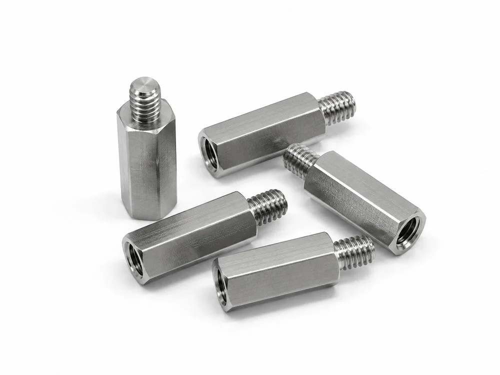
육각 스탠드오프의 암나사 깊이와 조립 높이 반복성
육각 스탠드오프와 암나사 스페이서는 전장 부품, 브라켓, 케이스, 장비 프레임에서 간격을 유지하고 체결 높이를 고정하는 부품입니다. 외형은 단순 육각봉처럼 보이지만 실제 기능은 양단 체결면, 암나사 깊이, 외나사 길이, 육각 평면, 조립 높이의 반복성으로 결정됩니다.
암나사 깊이가 부족하면 유효 체결 길이가 짧아지고, 나사산 바닥에 버가 남으면 볼트가 끝까지 들어가지 못합니다. 외나사가 함께 있는 구조에서는 외나사 중심축, 암나사 중심축, 육각 외형 기준이 크게 벗어나지 않아야 조립 높이와 체결 방향이 안정됩니다. 나사 게이지만 통과해도 실제 체결면 직각도가 나쁘면 구조물은 기울어질 수 있습니다.
스탠드오프는 여러 개가 동시에 사용되는 경우가 많습니다. 하나의 부품 높이 편차는 작은 오차처럼 보이지만, 다점 체결 구조에서는 PCB, 커버, 브라켓, 패널을 비틀 수 있습니다. 따라서 조립 높이, 양단면 평행도, 체결면 조도, 나사산 유효 깊이, 모서리 품질을 함께 봐야 합니다.
기능면 기준으로 보면 육각 스탠드오프는 간격 부품이자 체결 부품입니다. 치수 공차만으로는 충분하지 않고, 체결 후 실제 높이가 반복되는지, 볼트가 끝까지 안정적으로 들어가는지, 양단면이 상대면과 균일하게 닿는지가 중요합니다.
CNC 선삭 밀링 복합가공 부품의 기능면 품질 기준은 기준축, 기준면, 체결축, 표면 조도, 버 관리가 하나의 검사 흐름으로 연결될 때 완성됩니다.
English Technical Overview
Functional Surface Quality in CNC Turn-Mill Components
CNC turn-mill components should not be evaluated as a loose collection of dimensions. They are compact mechanical systems in which a turned datum axis, a milled datum face, a bored internal diameter, a threaded fastening axis, a counterbore seat, a shoulder face, a fork slot, and a deburred edge all contribute to the final assembly function. A part can satisfy several linear tolerances and still fail to assemble correctly if the actual functional surfaces are not related to the correct datum structure.
The essential question is not whether the component looks symmetrical. The more useful question is which feature controls the real function: the bore that guides a shaft, the outside diameter that locates the part in a housing, the flange face that receives clamping load, the pin hole that defines a hinge axis, or the thread that converts torque into fastening force. Once that priority is clear, machining sequence, datum transfer, surface finish, burr control, and inspection method can be planned as one quality system.
Turn-mill parts are especially sensitive to this issue because they combine rotational features and prismatic features. Turning produces coaxial diameters, shoulders, grooves, bores, tapers, and threads around a main spindle axis. Milling introduces flats, hex faces, fork slots, cross holes, counterbores, and side features that may be created after indexing, repositioning, or transferring the work coordinate system. The transition between those two worlds is where many functional quality problems begin.
Datum Strategy Before Tolerance Strategy
A datum strategy must be decided before a tolerance strategy can become meaningful. In cylindrical components, the central axis is often the first candidate because it represents rotation, insertion, or coaxial assembly. In flange components, the primary functional datum may instead be the seating face. In clevis components, the pin axis and fork-slot geometry may be more important than the threaded shank. In standoffs, the end faces and thread axis define the repeatable assembly height.
For a turn-mill component, the datum axis and datum face should be selected by assembly behavior rather than by machining convenience alone. If a bore guides a moving shaft, the bore axis should drive the inspection logic. If a flange transfers clamping force, the flange face should be treated as a critical bearing surface. If a cross hole carries a pin, the projected axis and slot parallelism may control the real functional risk more than the outer shape.
This is why geometric controls such as runout, total runout, position, perpendicularity, parallelism, flatness, and profile are more useful than isolated plus-minus dimensions for complex machined parts. They describe how one feature behaves relative to another feature. In practical inspection, that relationship is what determines whether a part will locate, rotate, clamp, space, or articulate correctly.
Axis-Controlled Features: Bores, Tapers, Shoulders, and Threads
Tapered bore sleeves, flange bushings, stepped shafts, and shoulder screw-type components all depend on a stable datum axis. A bore may guide a shaft, a taper may control contact distribution, an outside diameter may fit into a housing, and a shoulder may set the axial stop position. These features should not be checked as independent surfaces when they function together around the same centerline.
Concentricity language is often used casually, but the inspection requirement is usually broader. The practical concern may be runout of an outside diameter relative to a bore, total runout of a stepped surface, squareness of a shoulder to the axis, or position of a threaded feature relative to the body. If the measurement method only compares nominal diameters, it may miss eccentric contact and rotational instability.
Tapers add another layer of difficulty because the angle and the axis both matter. A taper that has the correct included angle can still seat poorly if the axis is offset or if the entrance chamfer contains a hard burr. For functional review, taper angle, contact band, bore finish, shoulder squareness, and edge condition should be reviewed together.
Milled Features: Flats, Hex Faces, Fork Slots, and Counterbores
Milling introduces surfaces that may define orientation, wrench engagement, bolt seating, pin clearance, or anti-rotation behavior. Hex faces on a taper boss, milled U-slots on clevis components, and counterbored bolt seats on flange rings are not secondary cosmetic features. They translate machining accuracy into practical assembly behavior.
A hex face may look acceptable by across-flat dimension, but the functional quality also depends on its relationship to the bore or threaded axis. A fork slot may meet width tolerance, but if the two ears are not parallel or the pin holes are not aligned, the joint will not move smoothly. A counterbore may meet depth tolerance, but if the seating face is rough or burred, torque will not convert into uniform clamp load.
In this class of parts, datum transfer should be treated as a technical risk. Turning may establish a strong cylindrical axis, while milling requires indexing or a secondary coordinate setup. The connection between those operations must be protected through fixture design, probing, in-process checks, and final inspection references.
Inspection Matrix for Functional Surfaces
The matrix below summarizes how representative CNC turn-mill component types can be reviewed. The purpose is not to create a universal tolerance table. The purpose is to connect each geometry to its functional surface, likely failure mode, and practical inspection focus. This makes the article useful for drawing review, process planning, incoming inspection, and supplier quality discussions.
Functional Surface Quality Matrix for CNC Turn-Mill Components
This matrix mirrors the Korean technical table for international B2B readers. Hover over each cell to review why the item matters in precision machined components.
| Component type | Functional surface | Process control point | Inspection criterion | Quality risk | Design decision |
|---|---|---|---|---|---|
| Taper bore sleeve | Bore, taper OD, shoulder face | Taper angle, bore machining, datum axis | Concentricity, taper angle, bore finish | Eccentric fit, insertion issue, unstable contact | Datum-axis priority |
| Knurled stepped shaft | Knurl, stepped OD, external thread | Knurl pitch, OD step, thread cutting | Knurl depth, thread gauge, runout | OD growth, fastening issue, surface damage | Grip and thread zone separation |
| Counterbore flange ring | Flange face, center bore, counterbore | Facing, hole position, counterbore depth | Flatness, position tolerance, depth, chamfer | Bolt lift, interference, leakage risk | Fastening-face priority |
| Clevis joint | Fork slot, pin hole, thread | Slot milling, pin-hole drilling, thread machining | Pin-hole coaxiality, parallelism, slot width | Pin insertion issue, wear, eccentric load | Pin axis and thread axis definition |
| Hex standoff | Hex flats, internal thread, external thread | Tapped depth, external thread length, hex milling | Thread gauge, end-face squareness, height | Short thread engagement, height error, loosening | Assembly-height repeatability |
Taper bore sleeve
Inspection: concentricity, taper angle, bore finish, shoulder squareness.
Datum-axis priorityKnurled stepped shaft
Inspection: knurl depth, thread gauge, runout, OD growth.
Grip and thread zone separationCounterbore flange ring
Inspection: flatness, position tolerance, depth, chamfer.
Fastening-face priorityClevis joint
Inspection: pin-hole coaxiality, parallelism, slot width.
Pin axis and thread axis definitionHex standoff
Inspection: thread gauge, end-face squareness, assembly height.
Assembly-height repeatabilityThreads, Counterbores, and Fastening Stability
Threads and counterbores should be treated as load-transfer surfaces. An external thread needs correct pitch, effective length, flank condition, chamfered entry, and clean thread starts. An internal thread needs sufficient engagement depth, gauge acceptance, chip and burr removal, and stable bottom condition. The fastening face needs flatness, surface finish, and edge quality because it controls how torque becomes clamp load.
Small defects have a disproportionate effect in fastening zones. A burr under a bolt head reduces the true bearing area. A rough counterbore bottom can create uneven seating. A shallow tapped depth can reduce engagement length. A damaged first thread can make assembly feel tight even when the final joint is not stable. A precision fastening component should therefore be reviewed as a thread-seat system, not as a thread alone.
Shoulder screw-type parts show this clearly. If the shoulder locates a component, then the shoulder diameter and shoulder squareness may be more critical than the threaded end. If the thread provides the main structural clamp, then thread form, effective length, and bearing-face condition move higher in priority. The same physical part can have a different inspection hierarchy depending on its assembly role.
Knurling, Surface Texture, and Contact Function
Knurling is a functional surface created by controlled deformation or cutting. It can improve grip, press-fit retention, and manual operation, but it also changes the outside diameter, local surface hardness, and edge transition. The inspection of a knurled shaft should include pattern uniformity, pitch, height, end condition, outside diameter growth, and the separation between the knurled zone and threaded zone.
Surface texture must also be interpreted by function. A sliding bore, a clamping flange face, a spacer face, a counterbore bottom, and a hand-grip knurled surface do not require the same texture logic. Average roughness alone may not capture peaks, valleys, lay direction, or localized damage that affects sealing, friction, or bearing contact. For functional surfaces, roughness parameters, visual condition, and contact behavior should be interpreted together.
Burr direction is part of surface integrity. A small burr at a pin hole can prevent smooth articulation. A burr inside an internal thread can stop a screw before full engagement. A rolled edge on a spacer can change the real assembly height. In precision components, deburring is not a final cosmetic step; it is part of functional surface control.
Clevis, Bushing, Spacer, and Standoff Inspection Priorities
Clevis components require careful control of fork slot width, ear parallelism, pin-hole coaxiality, internal corner condition, and thread-axis alignment. If the holes are not aligned, pin insertion becomes difficult and the joint may wear unevenly. If the fork ears are not parallel, the pin may carry bending load instead of clean shear or rotational load. If the internal slot corners are sharp or burred, the component can experience interference or stress concentration at the most sensitive transition.
Flange bushings and sleeves require a different inspection logic. The bore often guides motion, while the outside diameter or flange controls location in the surrounding structure. Bore finish, bore cylindricity, outside diameter tolerance, flange-face flatness, shoulder squareness, and chamfer condition all need to be reviewed in the same coordinate system. A bushing that is dimensionally correct but axis-shifted can still create noise, wear, or seal instability.
Spacer washers and precision rings control distance and load distribution. Their quality is not only thickness tolerance. Flatness, parallelism, burr height, edge break, surface texture, and inner/outer diameter relationship affect how the clamping force is distributed. When several spacers are assembled together, small height differences become a system-level alignment problem.
Hex standoffs combine spacing and fastening functions. Internal thread depth, external thread length, end-face squareness, thread-axis alignment, and repeatable assembly height determine whether the mounted structure remains flat and stable. A standoff may pass a simple thread gauge and still fail as a spacing component if the end faces are not controlled.
Process Planning and Inspection Flow
A robust review begins with the part function, not with the machining operation name. First, identify the primary functional datum: bore axis, outside diameter, flange face, shoulder face, pin axis, or thread axis. Second, define which secondary surfaces must remain related to that datum. Third, decide which inspection method can represent the actual assembly condition: CMM, air gauge, thread gauge, dial runout, surface roughness tester, optical measurement, fixture gauge, or on-machine probing.
On-machine probing can reduce predictable setup errors by confirming datum features and work coordinate systems before or during cutting. CMM inspection can evaluate the final geometric relationship between features. Dedicated gauges can support repeatable pass/fail decisions for high-volume features. None of these methods is sufficient by itself unless the datum structure matches the real function of the part.
For CNC turn-mill components, the strongest quality standard is usually created by linking process and inspection: rough turning to establish stock, finish turning for datum axis, milling based on the controlled axis or face, hole/thread creation after datum confirmation, edge finishing matched to function, and final inspection against the same datum logic. When those steps are separated, even a visually excellent part can carry hidden assembly risk.
Practical Quality Standard for Turn-Mill Parts
The practical standard is simple in concept but demanding in execution. A functional surface must be measured from the datum that represents its real use. A bore that guides motion should be checked as a guiding feature. A flange face that carries clamp load should be checked as a bearing surface. A pin hole that creates a hinge should be checked as an axis, not only as a circular hole. A thread that locates height or carries load should be checked together with the seating face and engagement depth.
This approach makes CNC turn-mill quality easier to explain and harder to misunderstand. It separates cosmetic machining quality from functional machining quality. It also prevents unnecessary tolerance tightening by focusing attention on the features that actually control assembly. The result is a more coherent technical review for shafts, sleeves, flange rings, bushings, clevis joints, spacer washers, shoulder screws, and standoffs.
High-grade CNC machining is therefore not defined by a single tight tolerance. It is defined by the disciplined connection between datum axis, datum face, fastening axis, surface texture, edge condition, and inspection method. When these elements are planned together, CNC turn-mill components can maintain stable assembly behavior across repeated production lots and across different mating conditions.
추가 정보
검색엔진용 요약
CNC 선삭 밀링 복합가공 부품은 원통 기준과 평면 기준, 내경과 외경, 나사산과 체결면, 홀 위치도와 표면 조도를 동시에 관리해야 하는 정밀 부품군입니다. 샤프트, 플랜지 링, 부싱, 클레비스, 스탠드오프처럼 형상이 다른 부품도 실제 품질 판단은 기능면과 조립 기준면을 어떻게 연결하느냐에 따라 달라집니다.
핵심 포인트 정리
- 선삭 부품은 외경 단차, 내경, 어깨부 기준면, 동심도, 런아웃 관리가 중요합니다.
- 밀링이 결합된 복합가공 부품은 U홈, 육각면, 평면, 핀홀 위치도가 조립 기준에 직접 연결됩니다.
- 널링, 나사산, 카운터보어, 렌치홈은 형상 자체보다 기능면 품질과 버 방향이 중요합니다.
- 정밀 와셔와 스페이서 링은 두께 공차, 평탄도, 평행도, 내외경 모따기 상태를 함께 확인해야 합니다.
- 클레비스 조인트와 스탠드오프는 체결축, 핀축, 나사축의 기준 관계가 품질을 좌우합니다.
- 표면 조도는 외관 요소가 아니라 접촉 안정성, 마찰, 체결력, 조립 반복성에 영향을 주는 기능 항목입니다.
FAQ
CNC 선삭 밀링 복합가공 부품에서 기능면이란 무엇입니까?
기능면은 조립, 회전, 체결, 위치 결정, 하중 전달, 접촉 안정성에 직접 영향을 주는 면입니다. 외경, 내경, 어깨부, 플랜지면, 홀 주변, 나사산 시작부, U홈 내측면처럼 실제 성능과 연결되는 면이 여기에 포함됩니다.
선삭 부품에서 동심도와 런아웃은 왜 중요합니까?
축형 부품은 여러 외경 단차와 내경이 하나의 중심축을 기준으로 작동합니다. 동심도와 런아웃이 불안정하면 회전 흔들림, 조립 편심, 베어링 간섭, 씰링 불량이 발생할 수 있습니다.
널링 샤프트는 표면 패턴만 보면 충분합니까?
널링은 미끄럼 방지나 압입 유지력에 쓰이지만 패턴의 깊이, 피치, 눌림, 끝단 말림까지 함께 봐야 합니다. 과한 널링은 외경 팽창이나 표면 균열을 만들 수 있어 기능면 기준 검사가 필요합니다.
플랜지 링에서 카운터보어 품질은 어떤 기준으로 봐야 합니까?
카운터보어는 볼트 머리 안착, 체결면 평탄도, 홀 위치도와 연결됩니다. 깊이 편차, 모서리 버, 홀 주변 표면 조도가 맞지 않으면 체결력이 균일하게 전달되지 않을 수 있습니다.
클레비스 조인트 부품은 어떤 공차가 중요합니까?
U홈 폭, 양쪽 귀의 평행도, 핀홀 동축도, 나사부 중심축, 어깨부 기준면이 중요합니다. 핀홀 정렬이 맞지 않으면 힌지 운동이 뻑뻑해지거나 편마모가 발생할 수 있습니다.
스탠드오프 부품은 외형보다 나사 품질이 더 중요합니까?
스탠드오프는 외형 기준면과 나사 품질을 함께 봐야 합니다. 암나사 깊이, 외나사 길이, 육각면 기준, 체결면 직각도가 맞아야 조립 높이와 체결 안정성이 반복됩니다.
정밀 와셔와 스페이서 링은 단순 평판 부품입니까?
정밀 와셔와 스페이서 링은 체결 압력, 간격 유지, 축방향 위치 결정에 쓰이는 기능 부품입니다. 두께 공차, 평탄도, 내외경 버, 표면 조도가 조립 품질에 직접 영향을 줄 수 있습니다.
관련 주제 확장 설명
기준면과 공정 순서
복합가공 부품은 첫 번째 공정에서 잡은 기준이 다음 공정의 홀, 평면, 홈, 나사산 위치까지 이어집니다. 따라서 도면에는 단순 치수보다 기준면, 기준축, 기능면 우선순위가 명확해야 합니다. 공정 순서가 바뀌면 최종 품질 기준도 달라질 수 있습니다.
표면 조도와 기능면
표면 조도는 보기 좋은 가공흔을 만드는 문제가 아니라 접촉, 마찰, 씰링, 체결 안정성을 좌우하는 품질 항목입니다. 내경, 외경, 플랜지면, 카운터보어면은 필요한 조도 수준이 서로 다를 수 있습니다.
나사산과 체결 안정성
외나사와 암나사는 유효 길이, 시작부 모따기, 버 제거, 피치 상태, 체결면 직각도가 함께 맞아야 합니다. 작은 버 하나도 체결 토크와 실제 축력 전달에 영향을 줄 수 있습니다.
내부 링크
ID METAL의 최신 제조 기술 글은 인사이트에서 확인할 수 있으며, CNC 정밀가공 부품은 cnc정밀가공부품 항목과 직접 연결됩니다. 체결 구조가 포함된 클레비스, 스탠드오프, 샤프트류는 구조연결용 부품의 설계 관점과 함께 볼 수 있습니다.
전류 경로나 접촉면이 포함되는 가공 부품은 전기접점 기술과 연계될 수 있으며, 판재 기반 기능 부품과 비교할 때는 정밀프레스가공 부품, 케이블 조립 환경에서는 케이블와이어 하네스, 금속 접합 구조는 브레이징 및 금속접합소재도 함께 참고할 수 있습니다.