
프레스 힌지 제작:
컬링 성형부터 핀 조립·품질관리까지
프레스 힌지는 판재 끝을 말아 만든 너클에 핀을 끼워 두 날개를 연결합니다. 핵심은 둥근 외형보다 여러 너클이 같은 회전축을 이루고, 필요한 하중에서 원활하게 움직이면서 핀을 유지하는 것입니다. 블랭크 전개, 절단면, 컬링과 스프링백, 표면처리 후 간극이 이 기능을 함께 좌우합니다.
3D 설계도에서 블랭크 → 끝단 예비 컬 → 탭 세우기 → 컬링 완료 → 핀 조립의 형상을 선택해 비교할 수 있습니다. 조립 상태에서는 힌지 개폐 동작을 확인할 수 있으며, 본문 도해는 축 정렬·간극·하중 전달과 검사 위치를 차례로 연결합니다.
평판에서 회전 연결부까지
성형 단계를 골라 구조를 살펴보고, 조립 상태에서 힌지를 열어 보세요.
3D 가속을 사용할 수 없어 정적 형상을 표시합니다.
드래그·방향키로 회전 · Home 키로 시점 초기화
성형 단계
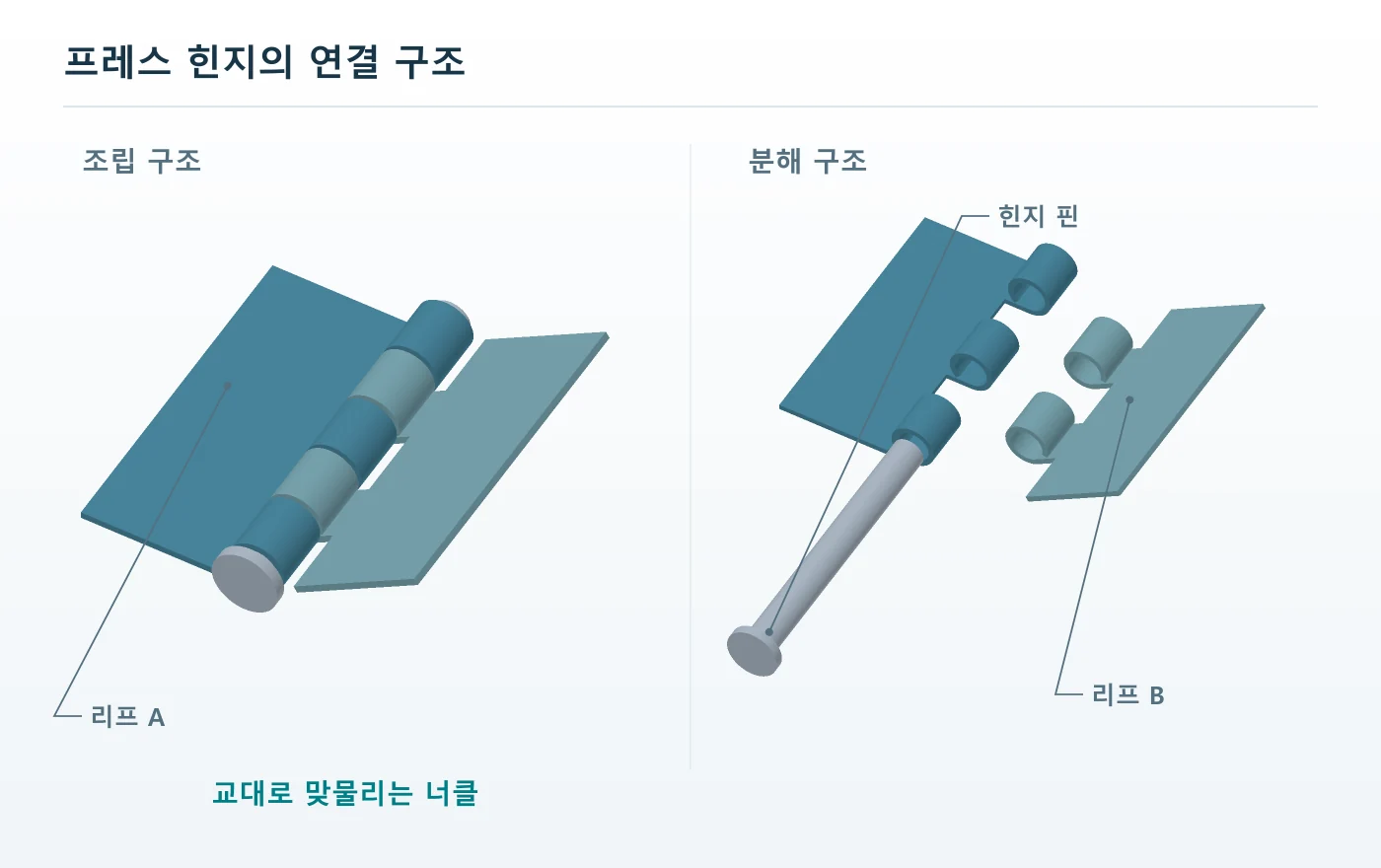
두 리프의 너클을 교대로 배치하고 핀으로 연결합니다.
두 리프를 평평하게 펼친 상태가 0°입니다. 제품의 허용 개폐각을 뜻하지 않습니다.
동작 줄이기 설정에 따라 자동 개폐가 정지됩니다.
단계별 형상을 설명하는 기하 모델입니다. 금형 접촉·응력·변형률·스프링백 해석이나 실제 제품 규격을 나타내지 않습니다.
형상에서 회전 기능까지
블랭크와 컬링 조건을 내경·축 정렬·장착 상태의 기능으로 연결합니다.
간극과 핀 유지의 구분
반경 간극, 축방향 유격, 작동 토크와 이탈 방지를 각각 정의합니다.
제작과 검증의 연결
성형·표면처리·조립 조건을 치수 검사와 개폐 내구 검증에 반영합니다.
01힌지 기능과 블랭크 설계
프레스 힌지의 기능과 하중 경로
프레스 힌지는 판재 끝을 원통형으로 말아 만든 너클과 그 안을 통과하는 핀으로 회전축을 구성합니다. 두 힌지 날개가 번갈아 배치된 너클을 통해 연결되며, 하중은 날개에서 너클 접촉면과 핀을 거쳐 반대쪽 날개로 전달됩니다. 따라서 외관이 원형이라는 사실만으로 조립성과 지지 성능을 판단할 수 없습니다.
힌지가 만족해야 할 기능은 서로 다릅니다. 커버를 가볍게 여닫는 구조는 작은 작동 저항을 요구할 수 있고, 흔들림을 줄여야 하는 구조는 회전축과 장착면의 위치 관계가 중요합니다. 일정 각도를 유지하는 마찰 힌지는 별도의 토크 설계가 필요하므로, 자유 회전 힌지의 간극을 무작정 줄여 같은 기능을 만들려 해서는 안 됩니다.
날개·너클·핀의 역할
날개는 장착 볼트나 용접부로 들어온 하중을 너클로 전달합니다. 너클은 핀을 감싸는 베어링 역할을 하지만, 얇은 판재로 성형한 이음매가 있는 원통이라는 특성을 가집니다. 핀은 연결과 회전 안내를 담당하며, 실제 구조에 따라 일부 너클에 고정되거나 전체 너클 안에서 움직일 수 있습니다.
| 기능 | 직접 관리할 항목 | 기능 확인 |
|---|---|---|
| 원활한 회전 | 내경 형상·축 정렬·표면·윤활 | 회전각에 따른 작동 토크 |
| 흔들림 억제 | 반경방향 간극·너클 배치·장착 강성 | 정해진 하중에서의 끝단 변위 |
| 축방향 위치 유지 | 너클 길이·끝면 간격·핀 유지 구조 | 축방향 유격과 핀 이동 |
| 구조 하중 지지 | 핀·너클·날개·장착부의 하중 경로 | 하중 시험 후 변형과 기능 |
장착 조건도 부품 형상만큼 중요합니다. 힌지 하나가 받는 힘은 문이나 커버의 질량뿐 아니라 무게중심의 거리, 힌지 간격, 지지부 강성에 따라 달라집니다. 힌지를 여러 개 사용하더라도 축이 어긋나면 균등하게 하중을 나누지 못하고, 장착 볼트를 조이는 순간 회전 저항이 증가할 수 있습니다.
성형과 조립의 연결
기본 공정은 블랭크 가공, 예비 굽힘, 컬링 성형, 형상 확인, 핀 조립과 최종 검사로 이어집니다. 표면처리와 윤활의 순서는 피막의 성형 내구성, 내부 도달성, 조립 방법에 맞춰 정합니다. 실제 금형은 여러 동작을 결합할 수 있으므로 공정 명칭과 프레스 타수는 반드시 같은 수가 아닙니다.
이 글의 3D 도해는 블랭크부터 핀 조립까지의 단계별 형상을 선택해 비교하고, 완성 힌지의 개폐 동작을 확인할 수 있습니다. 설명용 형상을 사용하며 금형의 실제 가압 경로, 소재 두께 변화나 응력 분포를 계산하는 성형 해석은 아닙니다. 공정 순서와 조립 방향을 이해한 뒤 각 단계의 관리 항목을 연결하면 설계 판단이 쉬워집니다.
완성품에서 출발하는 공정 설계
프레스 힌지의 도면 검토는 완성 상태의 회전 범위, 허용 유격, 장착면과 핀 이탈 방지 요구에서 시작합니다. 이를 너클 형상, 블랭크 형상과 금형 동작으로 거슬러 올라가며 연결합니다. 처음부터 내경 한 항목에 모든 기능을 맡기기보다 회전·지지·위치 유지의 합격 기준을 나누어 정하는 편이 원인 분석에도 유리합니다.
블랭크 전개와 너클 배치
힌지 블랭크에는 장착 날개뿐 아니라 말려 들어갈 탭과 너클 사이의 절개부가 포함됩니다. 말림 방향의 전개 길이는 최종 내경과 감김 각도에 관련되고, 핀 축 방향의 탭 폭은 너클 길이에 관련됩니다. 서로 다른 두 방향의 치수를 구분해야 내경 수정과 축방향 간격 수정이 뒤섞이지 않습니다.
두 날개의 탭은 조립 시 번갈아 들어가야 하며, 절개부에는 상대 너클이 들어올 공간과 끝면 여유가 필요합니다. 대칭으로 보이는 외형도 너클 배열과 핀 삽입 방향에 따라 서로 다른 좌우 부품이 될 수 있습니다. 완성 조립체와 펼친 블랭크를 함께 검토하면 뒤집힘이나 배열 오류를 일찍 찾을 수 있습니다.
중립층과 전개 길이
굽힘에서는 바깥쪽 섬유가 늘어나고 안쪽 섬유가 줄어들며, 그 사이의 길이 변화가 작은 층을 기준으로 굽힘 여유를 추정합니다. 일반적인 K계수 방식은 중립층의 위치를 판 두께에 대한 비율로 표현합니다. 그러나 이 비율은 모든 재질과 굽힘 형상에 일정한 물성값이 아니므로 하나의 표 값을 완성 힌지에 그대로 적용하면 오차가 생길 수 있습니다.
컬링은 큰 감김 각도, 소재 끝단과 금형의 접촉, 마찰과 부분적인 구속이 함께 작용합니다. 원호 길이 계산은 초기 블랭크를 정하는 출발점으로 사용할 수 있지만, 이음매 틈과 완성 내경을 동시에 보증하지는 않습니다. 초기 전개값을 실제 성형 후 내경·감김 각도·끝단 위치와 대조해 보정해야 합니다.
절개부와 탭 뿌리
너클 사이 절개부의 끝은 탭 뿌리에서 변형이 집중되는 위치와 연결됩니다. 날카로운 절개 끝, 거친 절단면이나 과도한 버가 있으면 컬링 중 균열의 시작점이 될 수 있습니다. 릴리프 형상을 정할 때는 균열 방지뿐 아니라 남는 날개 단면과 너클 지지 길이도 함께 확인합니다.
| 블랭크 항목 | 완성품과의 연결 | 초기 검증 |
|---|---|---|
| 말림 방향 전개 길이 | 감김 각도·이음매 위치·내경 | 성형 후 단면과 끝단 위치 |
| 축 방향 탭 폭 | 너클 길이·끝면 간격 | 상대 날개와 조립 치수 사슬 |
| 절개부 폭·끝 형상 | 상대 너클 진입·탭 뿌리 균열 | 간섭과 확대 표면 관찰 |
| 장착 홀과 컬링 기준 | 장착면에 대한 회전축 위치 | 공통 기준에서 위치 측정 |
전개 보정과 변경 추적
전개 길이를 수정할 때는 소재 두께와 강도, 금형 간격, 성형 깊이까지 동시에 바꾸지 않는 편이 원인을 구분하기 쉽습니다. 먼저 기준 조건을 고정하고 수정 전후의 형상을 비교합니다. 같은 도면 개정 안에 블랭크 변경과 금형 변경을 기록해야 이후 소재 로트가 바뀌었을 때 이전 보정의 이유를 추적할 수 있습니다.
장착 홀을 먼저 가공하면 후속 성형 위치의 기준으로 사용할 수 있지만, 홀 주변이 성형 영역과 가까우면 위치나 형상이 변할 수 있습니다. 반대로 성형 후 가공은 완성 형상을 기준으로 할 수 있으나 접근성과 추가 고정이 필요합니다. 기능상 중요한 축과 홀의 관계를 기준으로 가공 순서를 선택합니다.
02소재·절단면과 컬링 공정
소재 방향과 절단면 품질
컬링 적합성은 재질명만으로 정해지지 않습니다. 같은 계열의 판재라도 두께, 강도 수준, 가공경화 상태와 연신 특성에 따라 필요한 성형력과 균열 여유가 달라집니다. 소재를 바꿀 때는 화학 성분뿐 아니라 공급 상태와 두께 허용차를 함께 확인해야 기존 금형 조건을 유지할 수 있는지 판단할 수 있습니다.
압연된 판재는 방향에 따라 굽힘 거동이 달라질 수 있습니다. 일반적으로 굽힘선과 압연 방향의 관계를 관리하며, 작은 반경으로 반복해서 말아 넣는 형상일수록 실제 소재 방향을 기록하는 것이 유용합니다. 방향만으로 합격을 보장하지는 않으므로 재질·반경·절단면을 같은 조건으로 묶어 확인합니다.
인장 측 절단면과 균열
블랭킹 단면에는 눌림, 전단면, 파단면과 버가 함께 생길 수 있습니다. 이 가장자리가 컬링의 인장 측으로 늘어나면 기존 미세 손상과 날카로운 형상이 균열 발생에 영향을 줍니다. 버 방향을 검토할 때는 바깥쪽 인장면과 핀 접촉면을 동시에 살펴야 하며, 방향을 뒤집는 것만으로 손상된 절단면이 회복되지는 않습니다.
절단 간극과 공구 마모는 가장자리 품질을 바꾸며, 그 영향은 성형 단계에서 드러날 수 있습니다. 따라서 컬링 균열이 발생했을 때 성형 금형만 조정하기보다 블랭크의 버 높이와 단면 상태부터 비교합니다. 프레스 금형 클리어런스와 절단 품질을 함께 보면 절단과 성형을 연결해 원인을 찾기 쉽습니다.
가공경화와 윤활 조건
성형이 진행되면 소성 변형을 받은 영역의 강도와 남은 변형 여유가 달라집니다. 예비 굽힘에서 이미 변형을 집중시킨 좁은 영역을 다음 공정에서 다시 강하게 접으면 균열 위험이 높아질 수 있습니다. 한 지점에 변형을 몰아넣기보다 소재가 금형을 따라 이동하는 경로와 접촉 길이를 검토하는 이유입니다.
윤활은 소재가 금형을 따라 미끄러지는 조건과 표면 전이를 바꿉니다. 부족하면 긁힘이나 응착이 생길 수 있고, 공급량과 점도가 달라지면 같은 금형에서도 성형 하중과 끝단 이동이 변할 수 있습니다. 윤활제를 정할 때는 성형성뿐 아니라 후속 세척, 도금과 사용 환경에 남는 잔류물도 확인합니다.
소재 변경의 승인 범위
소재 변경 승인은 완성 외형만 비교하는 절차가 아닙니다. 블랭크 가장자리, 성형 후 균열, 내경 분포, 축 정렬과 조립 토크를 같은 검사 방법으로 비교해야 합니다. 강도가 높은 소재로 바꿨다는 이유만으로 힌지의 허용 하중이나 피로 수명이 개선되었다고 결론 내리지 않으며, 변경된 형상과 접촉 조건까지 확인합니다.
예비 굽힘과 컬링 금형
예비 굽힘은 평평한 탭의 끝을 다음 금형 접촉부로 유도합니다. 도해에는 끝단을 먼저 예비 컬링하고 탭을 세운 뒤 너클을 완성하는 공정 예시를 사용했습니다. 시작 각도와 끝단 방향이 맞지 않으면 소재가 금형에 걸리거나 다른 위치에서 접힐 수 있으므로, 각 단계의 끝단 경로를 확인합니다.
컬링 금형은 곡면을 따라 소재를 유도하면서 감김을 진행합니다. 형상과 설비에 따라 예비 굽힘과 최종 말기를 여러 타수로 나누거나 일부 동작을 한 공구 안에서 결합할 수 있습니다. 특정 제조사의 다단계 공구 사례를 모든 힌지에 필요한 고정 타수로 해석해서는 안 됩니다.
내부 지지와 공구 접근
내부 지지봉이나 맨드릴은 공정에 따라 내경 형상을 제한하거나 지지하는 데 사용할 수 있습니다. 그러나 모든 컬링 금형에 같은 방식의 맨드릴이 들어가는 것은 아니며, 완성된 너클에서 공구를 빼낼 경로도 필요합니다. 양 끝이 막히는 형상이나 다른 성형부와의 간섭은 공구 설계를 크게 바꿀 수 있습니다.
| 공정 변수 | 변화가 전달되는 경로 | 확인할 결과 |
|---|---|---|
| 예비 굽힘 각도·끝단 위치 | 다음 금형의 접촉 시작점 | 접힘·걸림·말림 방향 |
| 금형 곡면·간격 | 소재 유동과 국부 구속 | 내경·편평부·표면 손상 |
| 성형 깊이·정지 위치 | 최종 감김과 압착 상태 | 이음매 틈·타원화·날개 변형 |
| 윤활·공구 표면 | 마찰과 응착 | 하중 변화·긁힘·끝단 이동 |
프레스의 공칭 가압력만으로 공정 적합성을 판단할 수는 없습니다. 필요한 스트로크 위치에서의 힘, 에너지, 금형 높이와 복귀·취출 공간을 함께 확인합니다. 여러 너클을 동시에 성형하면 하중의 합뿐 아니라 좌우 비대칭과 날개 지지 상태도 중요하므로, 프레스 톤수와 설비 선택을 공정 배치와 연결합니다.
성형 순서와 날개 지지
날개가 충분히 지지되지 않으면 컬링에 필요한 힘의 일부가 장착면을 휘게 만들 수 있습니다. 이미 성형한 인접 너클이 다음 금형에 닿는지도 확인해야 합니다. 공정 순서를 정할 때는 완성 형상 외에도 금형 진입, 지지면, 소재 이송과 성형품 취출의 공간을 단계별로 검토합니다.
프로그레시브 방식에서는 소재를 지지하는 캐리어와 파일럿 기준이 컬링 후에도 기능해야 합니다. 탭이 말리며 생기는 공간 변화와 스크랩 배출을 이송 방향에서 확인합니다. 단발 금형이나 별도 성형 공정을 사용할 때도 재고정 기준이 달라지면 축 위치가 흔들릴 수 있으므로, 동일한 기능 기준을 재현하는 고정 방법이 필요합니다.
금형 조건의 기준화
초기 승인 시에는 금형 식별, 성형 깊이, 소재 방향, 윤활 조건과 측정 결과를 연결해 기록합니다. 이후 내경이 변하면 소재 두께 변화인지, 금형 마모인지, 정지 위치 변화인지 구분할 근거가 됩니다. 최종 합격품 한 개만 보관하는 것보다 입력 조건과 결과를 함께 남겨야 재설정 시간을 줄일 수 있습니다.

03내경 형상과 축 정렬
스프링백과 내경 형상
금형 안에서 형성된 너클은 하중이 제거되면 탄성 변형의 일부가 회복됩니다. 이 스프링백 때문에 공구 곡면과 완성 내경이 일대일로 같아지지 않을 수 있습니다. 소재 강도와 두께, 굽힘 반경, 가공경화와 공정 구속이 회복량에 영향을 주므로 금형 치수만으로 완성품을 판정하지 않습니다.
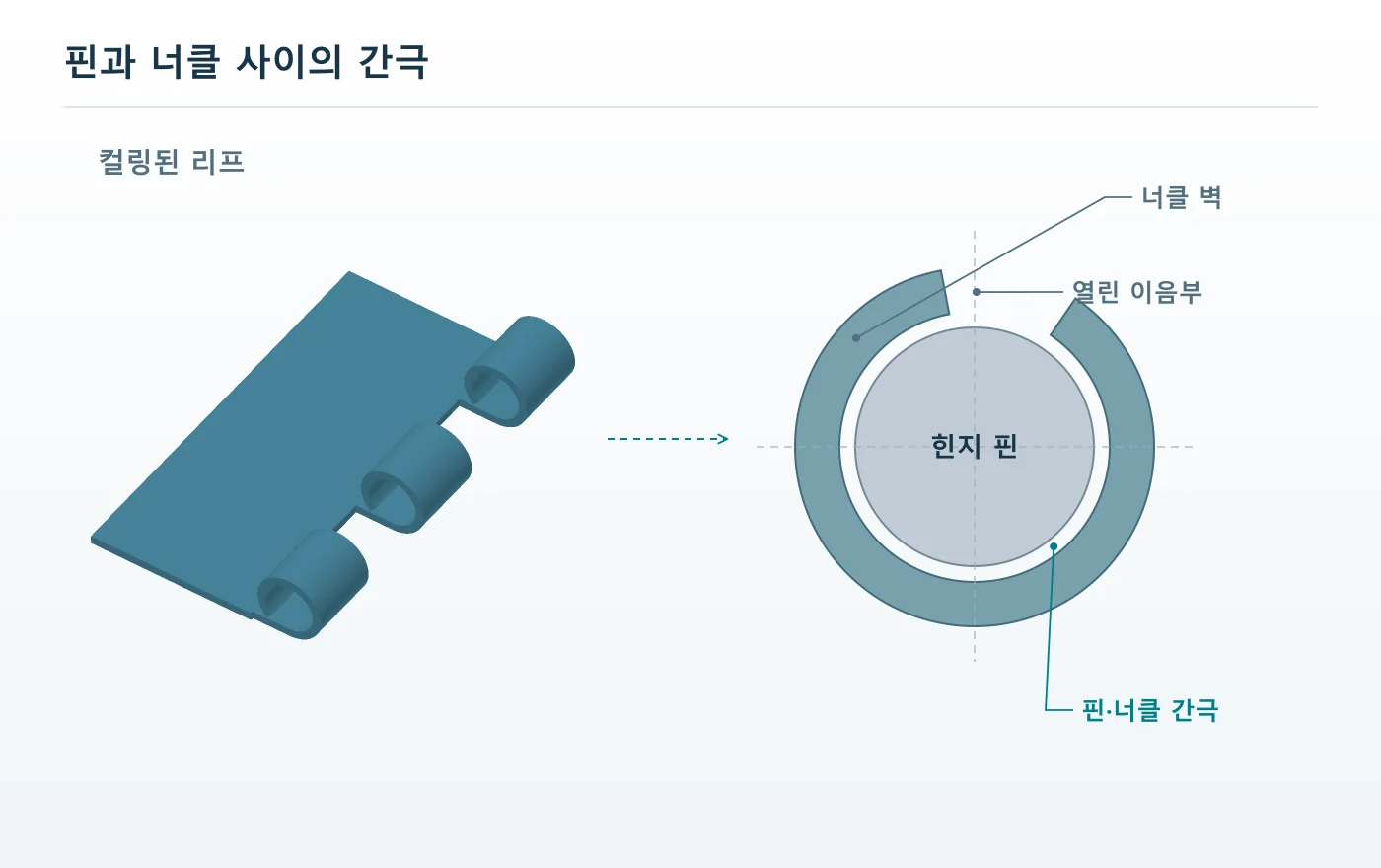
내경은 하나의 숫자로 표현되지만 실제 단면에는 타원형, 국부 편평부나 입구 벌어짐이 있을 수 있습니다. 핀은 가장 좁은 통로와 여러 너클의 상대 위치에 영향을 받으므로 특정 방향에서 측정한 지름 하나가 조립성을 대표하지 못합니다. 축 방향 여러 위치와 단면 방향을 나누어 형상을 확인하는 이유입니다.
감김 각도와 이음매 틈
컬링 끝단과 날개 쪽 시작부 사이의 틈은 내경과 연관되지만 같은 특성은 아닙니다. 전개 길이, 감김 각도와 끝단의 국부 변형이 틈에 함께 작용합니다. 틈을 닫기 위해 성형 깊이만 늘리면 내경이 눌리거나 날개가 변형될 수 있으므로, 내경과 이음매 위치를 별도 항목으로 비교합니다.
| 관찰 결과 | 우선 확인할 구분 | 판단에 필요한 비교 |
|---|---|---|
| 전체적으로 큰 내경 | 금형 형상·스프링백·성형 깊이 | 소재 로트와 해방 후 내경 |
| 한 방향만 작은 내경 | 타원화·국부 압착 | 둘레 방향 단면 측정 |
| 입구만 벌어짐 | 끝단 지지·공구 진입·국부 회복 | 입구와 중앙부의 형상 |
| 이음매 틈만 불균일 | 전개 길이·탭 기울어짐·끝단 이동 | 내경과 끝단 위치의 동시 기록 |
보정 방법에는 금형 형상 조정, 예비 형상 변경, 성형 깊이 조정과 별도 사이징 등이 있습니다. 어느 방법이 적절한지는 오차가 전체적인 크기 편차인지, 국부 형상 문제인지에 따라 달라집니다. 후속 사이징도 표면 손상과 가공경화를 추가할 수 있으므로 만능 교정 공정으로 취급하지 않습니다.
자유 상태와 측정 구속
얇은 너클은 측정하거나 고정하는 힘으로도 형상이 달라질 수 있습니다. 바이스나 측정 지그가 이음매를 닫도록 누르면 자유 상태보다 작은 내경이 측정될 수 있습니다. 검사 지지점과 측정력을 정의하고, 필요한 경우 자유 상태 형상과 실제 장착 상태 형상을 나누어 관리합니다.
플러그 게이지는 정해진 크기의 통과 여부를 빠르게 확인하지만, 불통과 원인이 내경 부족인지 축 어긋남인지까지 자동으로 알려 주지는 않습니다. 너클별 측정과 조립 길이에 맞는 기능 게이지를 함께 사용하면 원인을 좁힐 수 있습니다. 측정 장비의 분해능만큼 지지·접촉·정렬 방법의 반복성도 중요합니다.
소재 로트와 공정 분포
스프링백 보정은 한 번의 시제품에서 끝나는 작업이 아닙니다. 소재 로트와 두께 변화가 있는 생산 조건에서 내경의 평균과 산포를 확인해야 합니다. 평균만 중심에 맞추고 분포가 넓은 상태를 방치하면 같은 핀을 사용해도 헐거운 조립과 뻑뻑한 조립이 함께 발생할 수 있습니다.
너클 길이와 회전축 정렬
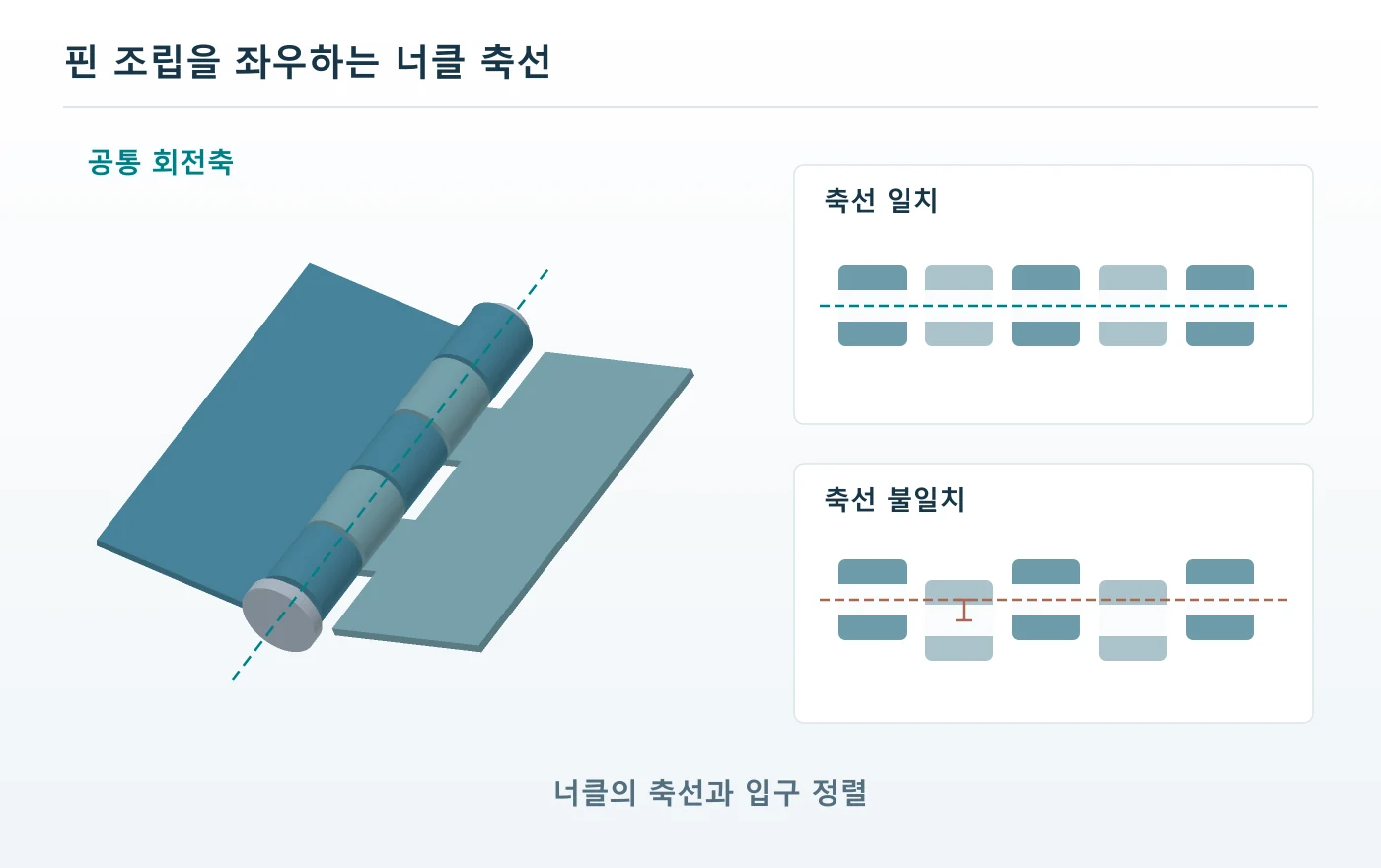
여러 너클이 하나의 핀을 공유하려면 각 구멍의 크기뿐 아니라 중심 경로가 연결되어야 합니다. 개별 너클에 짧은 핀이 들어가도 전체 길이의 핀이 통과하지 못할 수 있습니다. 반대로 가는 핀을 억지로 넣어 조립해도 핀이 휘어 내부 예압과 국부 마찰이 생길 수 있습니다.
축 정렬 문제는 탭의 비틀림, 날개 휨, 재고정 오차나 너클마다 다른 성형 조건에서 생길 수 있습니다. 원인을 찾으려면 같은 날개에 속한 너클끼리의 관계와 두 날개를 맞댔을 때의 관계를 나누어 봅니다. 이 구분은 금형 수정이 필요한지 조립 지그 수정이 필요한지 판단하는 데 도움이 됩니다.
기준면과 축 위치
힌지가 장착되는 면과 홀을 기능 기준으로 정하고 그 기준에 대한 회전축 위치를 관리합니다. 너클 외경만을 측정 기준으로 삼으면 두께 변화와 단면 형상이 축 위치 평가에 섞일 수 있습니다. 도면에서는 실제 조립 구속을 재현할 기준과 검사에서 구현 가능한 정렬 방법을 함께 정합니다.
긴 힌지는 작은 각도 어긋남도 끝단에서 큰 위치 차이로 나타날 수 있습니다. 여러 힌지를 떨어뜨려 장착하는 구조에서는 각 부품의 축이 공통 회전축을 이루는지도 확인합니다. 단품 치수와 완성 조립 기능의 차이는 정밀부품 공차 누적과 조립 간극의 관점으로 연결해 볼 수 있습니다.
축방향 길이 사슬
너클 길이와 절개 폭은 축방향 유격을 결정하는 치수 사슬을 만듭니다. 끝면이 맞닿도록 길이를 지나치게 채우면 회전 시 마찰이 증가하고, 여유가 너무 크면 날개가 축 방향으로 움직입니다. 핀 머리나 리테이너 위치까지 포함해 최종 조립 상태의 이동 여유를 확인해야 합니다.
| 특성 | 주요 기능 | 다른 항목과의 구분 |
|---|---|---|
| 너클 내경 | 핀의 국부 통과와 반경방향 여유 | 전체 축 정렬을 보증하지 않음 |
| 너클 축 정렬 | 핀의 전체 통과와 회전 안내 | 단일 내경 측정으로 대체 불가 |
| 너클 길이·끝면 간격 | 축방향 유격과 끝면 접촉 | 반경방향 간극과 별도 관리 |
| 장착면에 대한 축 위치 | 장착 후 운동과 간섭 | 자유 상태 조립만으로 판정 불가 |
기능 게이지와 장착 검증
기능 게이지는 도면이 요구하는 조립 조건을 재현해야 합니다. 게이지 지름, 통과 길이, 삽입 방향과 허용 힘이 모호하면 검사자마다 다른 결과가 나올 수 있습니다. 게이지가 지나간다는 결과와 일정 토크로 전체 회전 범위를 움직인다는 결과는 다른 검사이므로 각각의 합격 기준을 기록합니다.
최종 확인에서는 실제와 같은 지지 조건으로 날개를 고정하고 장착 전후의 토크와 유격을 비교합니다. 장착 후에만 저항이 커진다면 부품 자체 내경보다 장착면 평탄도, 홀 위치와 체결 순서를 먼저 의심할 수 있습니다. 검사 순서를 이렇게 나누면 부품 성형 문제와 조립 구속 문제를 분리할 수 있습니다.
04간극·표면처리와 핀 조립
반경 간극과 표면처리 여유
원형 내경 D와 원형 핀 지름 d가 같은 축을 이룬다는 단순 모델에서 직경 간극은 D − d입니다. 핀이 중앙에 있을 때 한쪽의 반경방향 여유는 그 절반입니다. 하중을 받아 핀이 한쪽 벽에 닿으면 양쪽 여유는 달라지므로, 이 단순 계산을 실제 접촉 상태와 구분해야 합니다.
최소 직경 간극은 가장 작은 완성 내경에서 가장 큰 완성 핀 지름을 뺀 값으로 확인합니다. 최대 간극은 그 반대 조합으로 확인합니다. 이 계산은 치수 허용 범위의 조합을 평가하지만, 타원도와 축 어긋남, 표면 돌기와 탄성 변형까지 포함한 회전 성능을 보증하지는 않습니다.
도금·도장 후의 최종 치수
핀 표면에 두께 h의 균일한 피막이 추가되면 지름은 양쪽을 합해 약 2h 증가합니다. 내경에도 같은 방식으로 피막이 쌓이면 통로는 양쪽에서 줄어듭니다. 따라서 핀과 너클을 각각 표면처리하는 구조는 한 부품의 피막 두께만 빼는 방식으로 최종 간극을 계산해서는 안 됩니다.
실제 피막은 이음매와 가장자리, 깊은 내부에서 균일하지 않을 수 있습니다. 도장 뭉침이나 조립 후 남은 잔류물도 좁은 통로와 끝면 마찰에 영향을 줍니다. 균일 피막 계산은 초기 검토에 사용하고, 도면의 내경·핀 치수와 기능 합격 기준은 지정된 최종 표면 상태에서 확인합니다.
서로 다른 네 가지 여유
| 여유 | 관리 대상 | 부족하거나 클 때의 영향 |
|---|---|---|
| 직경·반경 간극 | 핀과 너클 내부 | 끼임·마찰 또는 흔들림 |
| 축방향 유격 | 너클 끝면과 유지 구조 사이 | 끝면 압착 또는 축방향 이동 |
| 컬링 이음매 틈 | 말린 판재 끝의 위치 | 형상·강성·표면처리 상태 변화 |
| 회전 궤적 여유 | 날개·커버·주변 구조 | 특정 각도에서 외부 간섭 |
유격을 줄이기 위해 핀을 굵게 바꾸면 자유 회전 구간의 여유도 함께 줄어듭니다. 기존 불편의 원인이 큰 내경이 아니라 축 어긋남이나 끝면 간섭이었다면 문제를 키울 수 있습니다. 변경 전에는 어느 방향으로 움직임이 발생하는지와 회전각에 따라 저항이 어떻게 달라지는지를 먼저 기록합니다.
작동 환경과 표면 조합
마찰과 마모는 재질 조합, 표면 상태, 윤활과 이물 유입에 영향을 받습니다. 부식 생성물이나 분진이 들어가는 환경은 초기 검사실 상태와 다른 토크 변화를 만들 수 있습니다. 사용 환경에서 허용되는 윤활 방식과 세척 상태를 먼저 정한 뒤 그 상태로 조립과 내구 시험을 수행합니다.
작동 토크를 줄이는 방법은 간극 확대만이 아닙니다. 축 정렬, 끝면 상태, 표면처리 균일성과 윤활을 개선해도 마찰 원인을 줄일 수 있습니다. 반대로 작은 유격이 최우선인 설계에서는 회전 저항과 온도·오염에 대한 여유를 함께 평가해 기능 요구 사이의 절충을 결정합니다.
핀 조립과 이탈 방지
프레스 힌지의 핀은 회전축과 연결 부품이지만, 축 방향으로 빠지지 않게 하는 기능은 별도 구조가 맡습니다. 자유 회전이 필요한 너클까지 강하게 압입해 고정하면 조립은 유지되어도 정상적으로 움직이지 않을 수 있습니다. 어느 부위에서 핀을 고정하고 어느 부위에서 상대 회전이 일어나는지 도면에 구분합니다.
핀 유지 방식에는 머리와 반대쪽 끝 성형, 스테이킹, 링이나 별도 유지 부품, 특정 너클의 국부 고정 등이 있습니다. 분해 정비가 필요하면 영구적인 끝단 성형과의 양립성을 먼저 판단합니다. 필요한 유지력뿐 아니라 성형 후 축방향 여유, 날개 손상과 검사 접근성도 선택 기준입니다.
회전부와 고정부의 분리
솔리드 핀, 슬롯형 핀과 코일형 스프링 핀은 설치 과정에서의 변형과 유지 원리가 다릅니다. 탄성 핀의 권장 구멍 조건을 솔리드 핀에 그대로 적용하면 의도한 고정이나 회전 기능이 나오지 않을 수 있습니다. 핀 종류를 변경할 때는 상대 구멍, 고정 위치와 조립 힘을 함께 재검토합니다.
| 유지 방식 | 검토할 장점 | 함께 확인할 항목 |
|---|---|---|
| 핀 끝단 성형·스테이킹 | 추가 부품을 줄일 수 있음 | 분해성·끝단 균열·축방향 압착 |
| 링·별도 리테이너 | 설계에 따라 분해 가능 | 홈·장착 공간·이탈과 누락 검사 |
| 특정 너클의 국부 고정 | 고정 구간과 회전 구간을 구분 | 고정력·너클 변형·상대 회전 간극 |
| 탈착형 핀 구조 | 정비와 교체에 대응 | 사용 중 빠짐 방지와 조작 접근 |
조립 지그는 핀 삽입 방향을 축에 맞추고 필요한 너클을 지지해야 합니다. 핀 끝이 구멍 가장자리에 걸린 상태에서 가압하면 버가 말려 들어가거나 너클이 벌어질 수 있습니다. 삽입 힘이 증가했을 때 힘만 높이기보다 핀 진입부, 축 정렬과 표면 이물을 먼저 확인합니다.
삽입 힘과 완성 기능
삽입 힘의 이력은 조립 이상을 찾는 보조 지표가 될 수 있습니다. 특정 위치에서만 급증하면 한 너클의 기울어짐이나 국부 피막 누적을 의심할 수 있습니다. 다만 정상 범위는 핀 종류와 윤활, 조립 속도에 따라 달라지므로 다른 제품의 값을 그대로 합격 한계로 사용하지 않습니다.
유지 작업 후에는 핀이 빠지지 않는지만 확인하지 않습니다. 회전 토크와 축방향 유격을 다시 측정해 끝단 성형이 너클 끝면을 압착하지 않았는지 확인합니다. 정비형 구조라면 유지 부품을 해제하고 재조립하는 과정에서도 기능과 부품 손상이 허용 범위에 남는지 검토합니다.
3D 조립도와 실제 유지 구조
3D 조립도에는 머리가 있는 핀의 삽입 방향과 너클 배열을 표시했습니다. 반대쪽 끝의 유지 장치는 사용 목적에 맞춰 별도로 설계해야 합니다. 실제 제작 도면에는 선택한 이탈 방지 방식과 적용 위치, 허용 축방향 이동 및 분해 가능 여부를 명확히 지정합니다.
05하중·마모와 기능 검증
하중 전달과 마모 위험
힌지에 걸리는 하중은 핀의 전단만으로 설명되지 않습니다. 너클 사이 지지되지 않는 구간에서는 핀의 굽힘이 중요해질 수 있고, 너클 내부에는 접촉 압력이 작용합니다. 날개와 너클의 연결부, 장착 홀 주변과 체결 부품까지 같은 하중 경로에서 확인해야 합니다.
기초 검토에서는 하중을 핀 지름과 유효 지지 길이의 곱으로 나누어 평균 투영 면압을 비교할 수 있습니다. 여기서 유효 길이는 실제로 하중을 전달하는 길이입니다. 모든 너클 폭을 자동으로 합하거나 너클 개수로 하중을 똑같이 나누면 편심과 정렬 오차에 따른 집중을 놓칠 수 있습니다.
평균 면압과 실제 접촉
평균 면압은 국부 최대 접촉 압력이나 얇은 너클의 벌어짐을 직접 계산하지 않습니다. 핀이 휘거나 너클이 기울면 끝단 부근에 하중이 집중될 수 있습니다. 이런 경우 지지 길이를 늘리는 수정도 실제 접촉 분포를 개선하는지 확인해야 하며, 필요하면 접촉과 변형을 포함한 해석을 추가합니다.
| 위험 위치 | 주요 현상 | 설계·검증 연결 |
|---|---|---|
| 너클 사이 핀 | 굽힘·전단 | 지지 간격·핀 형상·영구 변형 |
| 너클 내부와 끝단 | 면압·편마모 | 축 정렬·접촉 길이·마모 흔적 |
| 너클 뿌리와 날개 | 굽힘·균열·피로 | 단면·성형 손상·반복 하중 |
| 장착부 | 판재 변형·체결부 이동 | 지지 강성·홀 배치·체결 조건 |
마모는 간극을 늘리는 방향으로 진행할 수 있지만, 초기에는 표면 눌림이나 피막 변화로 토크가 감소하거나 증가할 수도 있습니다. 결과를 단순히 길들여졌다고 해석하지 말고 유격, 표면 상태와 토크 변화를 함께 기록합니다. 어느 너클 끝에 마모가 집중되는지는 축 어긋남을 찾는 단서가 됩니다.
반복 하중과 열림 끝단
반복 개폐에서는 회전 마찰뿐 아니라 열림 끝단에 부딪히는 충격과 커버 흔들림도 작용할 수 있습니다. 힌지 자체가 스토퍼 역할을 하는지, 별도 스토퍼가 하중을 받는지에 따라 검증 조건이 달라집니다. 정적 하중을 한 번 견딘 결과만으로 반복 수명을 판단하지 않습니다.
부식이나 윤활 손실이 예상되면 환경 변화가 접촉부에 미치는 영향을 평가합니다. 표면처리의 목적이 외관인지 내식성인지 마찰 제어인지 구분해야 적절한 검사가 정해집니다. 부식 시험 결과와 개폐 내구 결과가 각각 합격하더라도 실제 사용에서 함께 작용할 조건을 놓치지 않아야 합니다.
허용 하중의 적용 범위
허용 하중을 제시하려면 장착 방향, 지지 구조, 하중 위치와 판정 기준이 함께 있어야 합니다. 같은 힌지도 하중 작용점이 회전축에서 멀어지면 날개와 장착부에 다른 모멘트가 걸립니다. 부품 재질이나 핀 지름 하나에서 완성품의 하중 정격을 바로 도출하지 않습니다.
치수 검사와 개폐 내구 검증
검사 계획은 블랭크, 성형품과 완성 조립체를 나누어 구성합니다. 블랭크에서는 전개와 절단면을, 성형품에서는 내경 형상과 축 위치를, 조립체에서는 토크·유격·핀 유지를 확인합니다. 앞 단계의 결과를 남겨야 완성품 불량이 발생했을 때 어느 공정으로 되돌아가야 하는지 판단할 수 있습니다.
내경 측정은 접근성과 필요한 정확도에 맞춰 게이지, 광학 측정이나 단면 관찰 등을 조합합니다. 얇은 너클의 접촉 변형과 측정 기준 설정이 결과에 미치는 영향을 확인합니다. 단면을 절단해 관찰할 때는 절단 과정에서 형상이 풀리거나 변형될 수 있으므로 비파괴 측정 결과와 대조합니다.
토크·유격·유지력의 분리
작동 토크는 정해진 장착 조건과 속도에서 회전각에 따라 측정합니다. 움직이기 시작할 때의 저항과 계속 움직이는 동안의 저항을 나누고, 특정 각도의 급증도 기록합니다. 유격 측정은 정해진 방향과 힘으로 수행하며, 핀 이탈 저항은 회전 토크와 별도 시험으로 확인합니다.
| 시험 | 고정해야 할 조건 | 기록할 결과 |
|---|---|---|
| 회전 토크 | 장착·속도·각도·윤활 상태 | 시작 저항·운동 중 토크·각도별 변화 |
| 축·반경방향 유격 | 하중 방향·측정력·측정 위치 | 초기값과 시험 후 증가량 |
| 핀 유지 | 밀기·당기기 방향·지지 조건 | 이동·이탈·유지부 손상 |
| 개폐 내구 | 하중·각도·속도·환경·윤활 정책 | 토크 추세·균열·마모·기능 저하 |
개폐 횟수만으로 내구 시험을 정의하면 실제 사용과 다른 결과가 나올 수 있습니다. 가벼운 무부하 회전과 편심 하중을 받는 커버 개폐는 같은 시험이 아닙니다. 요구 수명에 맞는 하중과 각도, 속도 및 중간 점검 시점을 정하고 시험 전에 불합격 기준을 합의합니다.
추세와 고장 형태
시험 중 토크가 계속 커지면 마찰 증가나 정렬 변화, 이물과 부식 등을 확인합니다. 토크가 작아지면서 유격이 커지면 접촉부 마모나 유지부 이동 가능성을 조사합니다. 시험 종료 후에는 외관뿐 아니라 너클 내부, 핀 접촉 흔적과 탭 뿌리의 균열을 함께 관찰합니다.
시험 지그의 변형이나 체결 풀림이 힌지 불량처럼 보일 수도 있습니다. 지그 강성과 장착 상태를 별도로 확인하고, 시험 전후에 같은 기준으로 치수를 측정합니다. 계측기의 교정 상태와 반복성을 확보한 뒤에야 작은 토크나 유격 변화가 제품에서 발생한 변화인지 구분할 수 있습니다.
시제품 승인과 생산 검사
시제품 승인 시험과 생산 중 검사는 목적이 다릅니다. 전자는 설계와 공정이 기능 요구를 충족하는지 확인하고, 후자는 승인된 상태가 유지되는지 감시합니다. 모든 제품에 긴 내구 시험을 적용하는 대신 위험도에 맞춰 공정 검사, 기능 검사와 주기적인 검증을 연결합니다.

06불량 진단과 제작 도면
불량 형태와 공정 원인
같은 증상에도 여러 원인이 있을 수 있으므로 불량을 외관 이름만으로 분류하지 않습니다. 핀이 안 들어가는 경우를 내경 부족으로 단정하면 축 어긋남이나 피막 누적을 놓칠 수 있습니다. 증상이 나타나는 위치, 발생 시점과 소재·금형 조건을 함께 기록하면 조사 범위를 줄일 수 있습니다.
균열은 발생 위치를 먼저 구분합니다. 말림 바깥면, 탭 뿌리나 절단면 끝에서 시작한 균열은 서로 다른 변형과 초기 손상을 가리킬 수 있습니다. 확대 관찰과 공정별 중간품을 비교해 처음 균열이 나타난 단계를 찾고, 그 단계의 소재와 금형 접촉을 조사합니다.
증상에서 측정으로
| 증상 | 가능 원인 | 다음 확인 |
|---|---|---|
| 핀 삽입 불가 | 내경 부족·축 어긋남·버·피막 | 너클별 통과와 전체 길이 통과 비교 |
| 특정 각도에서 걸림 | 외부 간섭·끝면 접촉·국부 형상 | 각도별 토크와 접촉 흔적 |
| 컬링 균열 | 소재 상태·절단 손상·변형 집중 | 최초 발생 단계와 균열 시작점 |
| 장착 후 뻑뻑함 | 장착면·홀 위치·체결 구속 | 장착 전후 토크와 축 위치 |
| 반복 사용 후 흔들림 | 편마모·핀 이동·날개 변형 | 방향별 유격과 분해 관찰 |
표면 긁힘과 소재 응착은 공구 표면, 윤활과 이물에 연결해 확인합니다. 긁힘을 없애기 위해 후처리만 늘리면 손상 원인은 남고 치수와 비용만 달라질 수 있습니다. 금형 표면 상태와 청소 주기를 점검한 뒤 손상 발생 빈도와 위치가 실제로 줄었는지 비교합니다.
평균 이동과 산포 증가
측정값이 일정한 방향으로 이동하는 경우와 값이 넓게 흩어지는 경우는 구분해야 합니다. 금형 위치 변화는 평균 이동으로, 불안정한 공급이나 고정은 산포 증가로 나타날 수 있지만 원인을 자동으로 확정할 수는 없습니다. 시간 순서의 측정값을 소재 로트와 금형 정비 기록에 연결해 검증합니다.
공정능력 수치를 계산하기 전에 측정 방법과 공정이 안정적인지 확인합니다. 서로 다른 소재 상태나 금형 설정에서 얻은 값을 한데 섞으면 단일 공정의 특성을 잘못 표현할 수 있습니다. 내경이 안정적이어도 축 정렬이나 토크가 변할 수 있으므로 기능에 중요한 항목을 함께 추적합니다.
수정 후 재검증 범위
내경을 교정하면 조립 토크와 유격이 함께 바뀔 수 있고, 너클 길이를 수정하면 축방향 유격과 지지 길이가 달라집니다. 수정 대상 치수만 다시 측정하지 말고 연결된 기능 검사를 정합니다. 여러 조건을 동시에 변경해야 한다면 변경 조합과 판단 근거를 기록해 이후 재현할 수 있게 합니다.
불량 대책의 종료 기준은 눈에 보이는 증상이 사라졌다는 사실만이 아닙니다. 승인 조건에서 치수와 조립 기능이 다시 충족되고, 필요한 반복 검증에서도 문제가 재발하지 않는지 확인합니다. 실제 발생 원인과 이를 감지할 검사 항목을 작업·검사 기준에 반영해야 같은 조정을 반복하는 일을 줄일 수 있습니다.
제작 도면과 공정·원가 설계
프레스 힌지 제작 도면에는 외형과 홀 치수만으로 설명되지 않는 기능 정보가 필요합니다. 어느 면으로 장착하며 어느 방향으로 하중을 받는지, 얼마나 회전하고 어느 정도의 토크와 유격을 허용하는지 명시합니다. 사용 조건이 있어야 내경과 축 위치 공차를 필요한 기능에 맞춰 배분할 수 있습니다.
재질은 등급과 공급 상태, 두께를 함께 지정하고 필요한 경우 소재 방향도 관리합니다. 표면처리 전후 어느 상태에서 치수를 판정하는지와 윤활 조건을 명확히 합니다. 핀 재질과 표면, 이탈 방지 방식과 정비 요구까지 함께 전달하면 성형과 조립을 서로 다른 가정으로 설계하는 일을 줄일 수 있습니다.
도면에 연결할 기능 정보
| 입력 자료 | 명확히 할 내용 | 공정 판단 |
|---|---|---|
| 조립도·사용 조건 | 장착·하중·회전 범위·주변 간섭 | 너클 배치·지지·검증 조건 |
| 부품 도면 | 기준·내경·축 위치·끝면·유격 | 금형·고정·측정 방법 |
| 소재·표면 사양 | 등급·상태·두께·피막·윤활 | 성형성·공정 순서·최종 간극 |
| 핀·유지 구조 | 고정 구간·회전 구간·분해성 | 조립 지그·유지 작업·기능 검사 |
| 수량·변경 전망 | 시제품·반복 생산·설계 변경 | 전용화 범위·금형·검사 투자 |
공정 선택은 수량 하나로 결정하지 않습니다. 전용 금형의 투자와 수정 비용, 기존 공구의 활용 가능성, 후속 조립 시간과 검사 난도를 함께 비교합니다. 반복 수요가 있더라도 형상 변경 가능성이 크면 처음부터 모든 공정을 한 금형에 통합하는 선택이 불리할 수 있습니다.
공차와 후공정의 비용
필요 이상으로 좁은 내경 공차는 사이징이나 선별을 추가할 수 있지만, 기능에 중요한 축 정렬이 빠져 있다면 그 비용으로 문제가 해결되지 않습니다. 먼저 회전과 지지 성능을 좌우하는 항목을 찾고, 나머지 치수는 제조와 검사가 가능한 범위에서 정합니다. 공차를 좁히는 일과 기능을 안정시키는 일을 구분합니다.
표면처리 후 조립은 부품별 피막 관리에 유리할 수 있지만 내부 치수 변화와 조립 중 흠집을 관리해야 합니다. 조립 후 처리하는 방식은 틈 안쪽 도달성과 자유 회전부의 피막 연결을 검토해야 합니다. 공정 순서는 외관뿐 아니라 완성 간극과 유지 구조, 검사 가능성까지 고려해 선택합니다.
시제품에서 생산 승인까지
시제품 단계에서는 블랭크와 성형 조건을 조정할 여유를 두고 기능 요구를 먼저 확인합니다. 형상이 안정되면 목표 생산 조건에서 치수 분포와 조립 결과를 확인하고 검사 기준을 확정합니다. 이 순서가 있어야 시제품 한 개의 원활한 움직임을 반복 생산의 안정성으로 오해하지 않습니다.
프레스 힌지의 완성도는 판재를 둥글게 말았다는 결과보다, 성형된 축이 필요한 하중에서 안정적으로 회전하고 핀을 유지하는지에 달려 있습니다. 도면·소재·컬링·표면처리·조립·검사를 같은 기능 기준으로 연결해야 합니다. 제작 검토에는 제품문의·개발의뢰를 통해 부품도와 조립 조건을 함께 전달하는 것이 도움이 됩니다.
English Edition · Press-Formed Hinges
A press-formed hinge connects two leaves with a pin passing through knuckles curled from sheet metal. The central requirement is a compatible rotation axis that supports the intended load, moves freely and retains the pin. Blank development, cut edges, curling, springback and finished clearances all influence this function.
Use the 3D drawing to compare blank → tip pre-curl → tab raising → completed curl → pin assembly. The assembled state also demonstrates opening and closing. The following illustrations connect axis alignment, clearances, load transfer and inspection locations to the corresponding engineering decisions.
From a flat blank to a moving joint
Inspect each forming stage, then articulate the assembled hinge.
3D acceleration is unavailable. A static geometric view is shown.
Drag or arrow keys to rotate · Home to reset
Forming stage
Alternating knuckles share a pin and a common axis.
0° is the flat-open reference. This illustration does not specify a rated product opening angle.
Automatic articulation is paused to respect reduced-motion preferences.
Illustrative staged geometry, not a simulation of die contact, stress, strain or springback. No product dimensions are specified.
From shape to rotation
Connect blank and curling conditions to bore geometry, alignment and installed function.
Clearance and retention
Define radial clearance, axial endplay, operating torque and pin retention separately.
Manufacture and validation
Reflect forming, finishing and assembly conditions in dimensional and endurance checks.
01Hinge function and blank design
Function and load path of a press-formed hinge
A press-formed hinge creates a rotational axis with a pin passing through knuckles curled from the ends of sheet-metal leaves. Alternating knuckles connect the two leaves. Loads travel from one leaf through the knuckle contact surfaces and pin into the other leaf. A circular appearance alone therefore does not establish assembly quality or load capacity.
Different hinges serve different functions. A frequently opened cover may require low operating resistance, while a positioning-sensitive assembly needs a controlled relationship between its rotation axis and mounting surfaces. A friction hinge designed to hold an angle requires a deliberate torque mechanism. Simply reducing the clearance of a free-running hinge is not an equivalent design method.
Roles of the leaf, knuckle and pin
The leaf transfers loads from mounting bolts or welds into the knuckle. The knuckle acts as a bearing around the pin, but it remains a thin formed shell with a seam. The pin connects the leaves and guides rotation. Depending on the design, it may be secured within selected knuckles or permitted to move relative to every knuckle.
| Function | Direct controls | Functional check |
|---|---|---|
| Smooth rotation | Bore shape, alignment, surface and lubrication | Operating torque through the angular range |
| Limited looseness | Radial clearance, knuckle layout and mounting stiffness | Endpoint displacement under a stated load |
| Axial location | Knuckle lengths, end gaps and pin retention | Endplay and pin movement |
| Structural support | Load path through pin, knuckles, leaves and mounts | Deformation and function after loading |
Mounting conditions matter as much as component geometry. The force on one hinge depends on the supported mass, its center-of-gravity distance, hinge spacing and support stiffness. Multiple hinges do not necessarily share loads equally. Misaligned axes can create additional constraints, and tightening the mounting bolts may increase rotational resistance even before the intended service load is applied.
Connecting forming to assembly
The basic sequence connects blank preparation, pre-bending, curling, geometry verification, pin assembly and final inspection. Coating and lubrication must be scheduled around film formability, access to internal surfaces and the assembly method. A particular tool can combine several actions. The number of named process stages therefore does not necessarily equal the number of press strokes required.
The interactive 3D drawing provides selectable stage geometries from the blank to pin assembly, together with opening and closing of the assembled hinge. Its explanatory geometry does not calculate tool loading paths, thickness changes or forming stresses. Understanding the sequence and assembly direction helps connect the control requirements of the individual operations.
Process planning from the finished function
Drawing review starts with the finished rotation range, permitted looseness, mounting interfaces and pin-retention requirements. These requirements are then traced back to knuckle geometry, blank geometry and tool movements. Defining separate acceptance criteria for rotation, support and axial retention is more useful than assigning every function to a single bore dimension. It also makes later fault diagnosis more specific.
Blank development and knuckle layout
A hinge blank includes the mounting leaf, the tabs that become knuckles and the cutouts between them. Development length in the curling direction relates to the finished bore and wrap angle. Tab width along the pin axis relates to knuckle length. These perpendicular dimensions must be distinguished so that bore corrections are not confused with changes to axial spacing.
The tabs of the two leaves must alternate in the assembled hinge. Each cutout needs space for the opposing knuckle and the required end clearance. Apparently symmetric outlines may still create handed parts because of knuckle order and pin insertion direction. Reviewing the assembled hinge beside both developed blanks helps expose reversed parts and incorrect knuckle sequences before tooling is committed.
Neutral layer and developed length
Bending stretches the outer fibers and compresses the inner fibers. Bend allowance is estimated using an intermediate layer with comparatively little longitudinal change. A conventional K-factor expresses the assumed position of that layer as a fraction of sheet thickness. It is not a universal material constant, so transferring one tabulated value directly to every curled hinge can produce development errors.
Curling combines a large wrap angle with contact between the sheet end and tool, friction and changing local restraint. An arc-length estimate is useful for an initial blank, but it does not independently guarantee both the seam gap and finished bore. Compare the first development with measured bore size, wrap angle and end position, then refine the blank accordingly.
Cutouts and tab roots
The ends of the cutouts meet the tab roots, where deformation can concentrate. Sharp cutout terminations, damaged cut edges and excessive burrs can initiate cracks during curling. Relief geometry therefore deserves deliberate review. A larger relief may ease local deformation, but its effect on the remaining leaf section and the length supporting each knuckle must also be considered.
| Blank feature | Finished-part relationship | Initial verification |
|---|---|---|
| Length in curling direction | Wrap angle, seam position and bore | Formed section and end location |
| Tab width along the axis | Knuckle length and end gaps | Assembly chain with opposing leaf |
| Cutout width and termination | Knuckle entry and tab-root cracking | Interference and magnified surface checks |
| Mounting holes relative to curl datum | Axis position relative to mounting surface | Location measurement from common references |
Development correction and change control
When correcting development length, avoid changing thickness, material strength, tool clearance and forming depth simultaneously. Fix a baseline and compare geometry before and after each meaningful correction. Record the associated blank and tool changes under controlled revisions. When a later material lot behaves differently, this history helps distinguish a new material effect from an earlier tooling compensation.
Mounting holes produced before forming can provide locating references for subsequent operations. However, nearby forming may distort them or shift their position. Producing them afterward allows reference to the finished shape but requires access and additional fixturing. Select the sequence from the functional relationship between the rotation axis and mounting holes, rather than assuming one order is always preferable.
02Material, cut edges and curling
Material direction and cut-edge quality
Curling suitability is not determined by the material name alone. Thickness, strength level, work-hardened condition and ductility affect forming force and the margin against cracking, even within one material family. A substitution review should therefore include delivery condition and thickness tolerance as well as chemistry. These details determine whether the existing tooling conditions remain appropriate.
Rolled sheet can behave differently with bending direction. The relationship between the bend line and rolling direction therefore deserves control, particularly when the geometry wraps material around a small radius. Record the actual stock orientation instead of relying on visual assumptions. Direction alone does not guarantee success; evaluate it together with material condition, radius and cut-edge quality.
Cut edges on the tensile side
A blanked edge may include rollover, a burnished region, a fractured region and a burr. When this edge is stretched on the tensile side of a curl, existing damage and sharp features can influence crack initiation. Burr orientation should be assessed against both tensile deformation and pin contact. Reversing the blank does not restore an already damaged cut edge.
Cutting clearance and tool wear change edge quality, and their consequences may become visible only during forming. When curls crack, compare burr height and edge condition before adjusting the forming tool alone. The relationship between cutting and subsequent deformation is discussed further in press die clearance and cut-edge quality.
Work hardening and lubrication
Plastic deformation changes the strength and remaining deformation capacity of the formed region. A narrow area heavily strained during pre-bending may become vulnerable when the next operation bends it again. This is why process planning considers the path of material movement and tool contact length, rather than concentrating all deformation at one small location.
Lubrication changes sliding conditions and material transfer at the tool surface. Insufficient lubrication can promote scratching or pickup, while changes in quantity or viscosity can alter forming load and end movement with the same tooling. Selection must also consider subsequent cleaning, coating compatibility and residues that might remain in the service environment.
Approval scope for material changes
Approval of a material change requires more than comparing the outside shape. Use consistent methods to compare cut edges, post-forming cracks, bore variation, axis alignment and assembly torque. A higher-strength material does not automatically establish greater hinge capacity or longer fatigue life. The resulting geometry and contact conditions must be evaluated as part of the change.
Pre-bending and curling tools
Pre-bending directs the tab end toward the next tool contact. The illustrated example first pre-curls the tip, raises the tab and then completes the knuckle. An unsuitable angle or tip direction can cause catching or folding at the wrong location. Follow the end position through the individual stages when reviewing tool operation.
A curling tool guides the sheet around a curved contact path as the wrap develops. Depending on geometry and equipment, pre-bending and final curling may use separate strokes, or a tool may combine some actions. A multistage example from one tooling manufacturer should not be interpreted as a mandatory stroke count for every press-formed hinge.
Internal support and tool access
An internal support or mandrel can constrain or support the bore in some processes. It is not a universal feature of every curling tool, and the tool must still have a withdrawal path after forming. Closed ends or interference with adjacent formed features can significantly change the feasible tooling arrangement and the sequence of operations.
| Process variable | Physical influence | Result to check |
|---|---|---|
| Pre-bend angle and tip position | Initial contact with the next tool | Folding, catching and curl direction |
| Tool curve and clearance | Material flow and local restraint | Bore, flattened regions and surface damage |
| Forming depth and stop position | Final wrap and compression | Seam gap, ovality and leaf distortion |
| Lubrication and tool surface | Friction and pickup | Load changes, scratching and tip movement |
Nominal press capacity alone does not establish process suitability. Check available force at the required stroke position, energy, shut height and space for return and removal. Simultaneous formation of several knuckles also introduces questions of load balance and leaf support. Relate press capacity and equipment selection to the actual station arrangement.
Forming sequence and leaf support
If the leaf is inadequately supported, part of the forming load can bend the mounting surface instead of producing the intended curl. Previously formed neighboring knuckles may also interfere with the next tool. Review tool entry, support surfaces, material transfer and finished-part removal at every stage. These practical clearances can govern the process sequence as strongly as the final geometry.
In a progressive tool, the carrier and pilot references must remain effective as the tabs curl. Check the evolving part envelope and scrap removal against the feed direction. Separate forming operations create a related issue: each refixturing step may shift the axis if its locating references differ. The fixture must reproduce the functional reference scheme consistently.
Establishing a tooling baseline
At initial approval, link tool identification, forming depth, stock direction and lubrication conditions to the measured results. This creates a basis for separating later bore changes caused by material thickness, tool wear or stop-position drift. A retained acceptable sample is useful, but recorded inputs and outputs provide a stronger basis for efficient and repeatable setup.
03Bore geometry and axis alignment
Springback and bore geometry
After the tool load is removed, part of the elastic deformation in a formed knuckle recovers. This springback means the tool contour and finished bore need not match directly. Material strength, thickness, bend radius, work hardening and process restraint influence recovery. Finished-part acceptance must therefore rely on the released component rather than on tool dimensions alone.
A bore may be specified with one dimension while its actual section contains ovality, a local flat or a flared entrance. A pin responds to the narrowest passage and the relative locations of multiple knuckles. One diameter measured in one direction cannot represent all of these conditions. Inspect at several axial positions and relevant cross-sectional orientations.
Wrap angle and seam gap
The gap between the curl tip and its root relates to bore geometry, but it is not the same characteristic. Developed length, wrap angle and local tip deformation all contribute. Increasing forming depth simply to close the seam may compress the bore or distort the leaf. Evaluate the bore and seam position as separate outputs of the process.
| Observed result | Distinction to investigate | Useful comparison |
|---|---|---|
| Generally oversized bore | Tool contour, springback and forming depth | Material lot and released bore |
| Undersize in one direction | Ovality or local compression | Cross-section by orientation |
| Flared entrance only | End support, tool entry and local recovery | Entrance versus central section |
| Uneven seam gap | Development, tab skew and tip movement | Bore and end-position records together |
Possible corrections include tool-contour changes, a revised preform, forming-depth adjustment and a separate sizing operation. Selection depends on whether the problem is a general size shift or a local shape defect. Subsequent sizing can introduce additional work hardening and surface damage. It should therefore be evaluated as a process change rather than treated as an unlimited corrective operation.
Free state and measurement restraint
A thin knuckle can change shape under measuring or clamping forces. A vise or fixture that closes the seam may produce a smaller measured bore than the free component has. Define support points and measurement force. When necessary, distinguish free-state geometry from the geometry obtained under the specified mounting conditions instead of mixing the two results.
A plug gauge quickly checks passage at a defined size, but a failed passage does not automatically identify whether the bore is too small or the axes are misaligned. Combine individual-knuckle measurements with a functional gauge appropriate to the assembled length. Repeatability of support, contact and alignment matters as much as the nominal resolution of the instrument.
Material lots and process distribution
Springback compensation should not end with one successful prototype. Examine the bore mean and spread across the material lots and thickness variation expected in production. Centering the average without controlling a broad distribution can still produce both loose and tight assemblies with the same pin specification. The process must address variation as well as nominal geometry.
Knuckle length and rotation-axis alignment
Several knuckles sharing one pin need compatible bore sizes and an aligned center path. A short pin may enter every knuckle individually while a full-length pin cannot pass through the complete assembly. Forcing in a slender pin is not proof of alignment either. The pin may bend, introducing internal loading and concentrated friction before the hinge begins operating.
Axis errors can arise from twisted tabs, bent leaves, refixturing errors or different forming conditions among knuckles. Diagnose alignment within each leaf separately from alignment between the two assembled leaves. This distinction helps identify whether the correction belongs in the forming tool, locating scheme or assembly fixture, rather than changing all three without a clear cause.
Datums and axis location
Use the functional mounting surfaces and holes to establish references for the rotation axis. Referencing only the knuckle outside diameter can mix thickness variation and sectional shape into the axis assessment. The drawing should connect the references used in assembly to an alignment method that can actually be reproduced during inspection.
In a long hinge, a small angular error can produce a larger positional mismatch at the end. Where separate hinges are mounted apart, their individual axes must also form a compatible common rotation axis. The distinction between individual dimensional acceptance and assembled function connects directly to tolerance stack-up and assembly clearance.
The axial length chain
Knuckle lengths and cutout widths create the dimensional chain governing axial endplay. Filling the available length too tightly can force end faces together and increase rotational friction. Excessive space permits axial leaf movement. Include the pin head or retainer position when evaluating the movement that remains in the completed assembly, rather than checking the knuckle widths alone.
| Characteristic | Main function | Important distinction |
|---|---|---|
| Knuckle bore size | Local pin passage and radial allowance | Does not guarantee overall axis alignment |
| Knuckle axis alignment | Full-length pin passage and guidance | Cannot be replaced by one diameter check |
| Knuckle length and end gaps | Axial endplay and end-face contact | Separate from radial clearance |
| Axis relative to mounting surface | Installed motion and interference | Free assembly alone is insufficient |
Functional gauges and mounting checks
A functional gauge must reproduce the intended assembly condition. Unspecified gauge diameter, engagement length, insertion direction or allowable force can lead to inconsistent judgments. Passing a gauge and rotating through the full operating range at acceptable torque are different checks. Record their acceptance criteria separately so that one result does not silently substitute for the other.
For the final check, support the leaves as intended in service and compare torque and play before and after mounting. If resistance rises only after installation, investigate mounting flatness, hole position and tightening sequence before blaming bore size alone. This staged inspection separates defects originating in component forming from constraints introduced during final assembly.
04Clearance, finishing and pin assembly
Radial clearance and finishing allowance
For a round bore D and a round pin d on the same axis, diametral clearance is D − d. With the pin centered, the radial space on each side is half that difference. Once loading moves the pin against one wall, the two spaces are unequal. Distinguish the geometric calculation from the loaded contact condition.
Evaluate minimum diametral clearance using the smallest finished bore and largest finished pin. The opposite combination gives the maximum. These checks bound the permitted size combinations. They do not establish rotational performance in the presence of ovality, axis mismatch, surface protrusions or elastic deformation, which must be assessed separately.
Final dimensions after plating or painting
A uniform added film of thickness h on a pin increases its diameter by approximately 2h. A corresponding film inside the bore reduces the passage from both sides. If both components receive a coating, final clearance cannot be estimated by subtracting the film contribution from only one component. Both dimensional changes belong in the calculation.
Actual coverage may differ around seams, edges and internal recesses. Paint accumulation or remaining residues can also affect narrow passages and end-face friction. Use a uniform-film calculation for preliminary review, then verify dimensions and functional acceptance in the specified final surface condition. Nominal coating thickness alone is not sufficient evidence of finished clearance.
Four different clearances
| Clearance | Location | Possible consequence |
|---|---|---|
| Diametral or radial clearance | Pin and knuckle bore | Binding, friction or looseness |
| Axial endplay | Knuckle ends and retention features | End-face compression or axial movement |
| Curl seam gap | Position of the curled sheet end | Changes to shape, stiffness and finishing |
| Swept-motion clearance | Leaves, cover and surrounding structure | External interference at particular angles |
Increasing pin diameter to reduce looseness also reduces the allowance at the rotating interface. If the original problem was misalignment or end-face interference rather than an oversized bore, the change can worsen it. First identify the direction of unwanted movement and record how resistance changes with rotation angle.
Operating environment and surface pairing
Material pairing, surface condition, lubrication and contamination influence friction and wear. Corrosion products or dust can create torque changes that were absent in a clean initial inspection. Define the lubrication and cleanliness conditions permitted in service, then use those conditions in assembly and endurance evaluation rather than relying only on laboratory-clean operation.
Increasing clearance is not the only way to lower operating torque. Alignment, end-face condition, coating consistency and lubrication can also reduce its causes. When very limited play is the priority, evaluate the associated rotational resistance and tolerance to temperature or contamination. The decision should balance the actual functional requirements.
Pin assembly and retention
The pin provides the hinge axis and connects the leaves, while separate features prevent axial escape. Pressing it tightly into every knuckle can retain the assembly but prevent intended rotation. Identify the region that holds the pin and the interface that rotates relative to it. These are distinct functions and should be clear on the drawing.
Retention options include a head with an upset opposite end, staking, retaining rings or separate retainers, and local fixation in a selected knuckle. Required disassembly affects the suitability of permanent end forming. Selection should address retention force, remaining endplay, potential leaf damage and inspection access, rather than retention strength alone.
Separating rotating and retained regions
Solid, slotted and coiled spring pins behave differently during installation and retention. Hole guidance for an elastic pin cannot simply be transferred to a solid pin while assuming the same rotation or holding behavior. A pin-type change requires review of the mating bore, retention location and installation force as one connected design change.
| Retention method | Potential benefit | Associated checks |
|---|---|---|
| End forming or staking | Can reduce separate components | Disassembly, end cracking and axial compression |
| Ring or separate retainer | May permit disassembly | Groove, access, escape and omission checks |
| Local fixation in one knuckle | Separates held and rotating regions | Retention, shell distortion and running clearance |
| Removable-pin arrangement | Supports service and replacement | Unintended withdrawal and operating access |
The assembly fixture should align the insertion direction with the axis and support the relevant knuckles. Loading a pin that catches on a bore edge can fold a burr inward or spread the shell. If insertion force rises, inspect the lead-in, alignment and contamination before increasing the applied force.
Insertion force and finished function
An insertion-force trace can help locate assembly abnormalities. A sharp increase at one position may suggest a skewed knuckle or local coating buildup. The normal trace depends on pin type, lubrication and assembly speed, however. Establish limits for the actual process instead of borrowing acceptance values from a different product.
After retention is applied, do more than check that the pin remains present. Recheck rotation torque and endplay to detect end-face compression caused by the retention operation. For serviceable designs, evaluate removal and reassembly as well, including the resulting function and any damage to components intended for reuse.
The 3D arrangement and actual retention design
The 3D assembly shows the insertion direction of a headed pin and the knuckle arrangement. Retention at the opposite end must be designed separately for the application. The production drawing should specify the selected retention method, its location, permitted axial movement and whether the assembly must remain removable.
05Loads, wear and functional validation
Load transfer and wear risk
A hinge load cannot be represented by pin shear alone. Pin bending can matter across unsupported gaps, while contact pressure acts inside the knuckles. The leaf-to-knuckle transition, mounting-hole regions and fasteners also belong to the load path. Evaluate these elements together before assigning an assembly load rating.
A first screening can compare average projected bearing pressure by dividing load by pin diameter times effective supporting length. That length must represent the portion actually carrying the load. Automatically summing every knuckle width or dividing force equally among knuckles can overlook concentration caused by eccentricity and alignment errors.
Average pressure and actual contact
Average pressure does not directly predict local peak contact stress or opening of a thin knuckle. Pin bending and knuckle tilt can concentrate loads near an end. Even an increase in nominal supporting length should be checked for its effect on real contact distribution. Contact and deformation analysis may be needed where these effects govern performance.
| Location | Main concern | Design and validation |
|---|---|---|
| Pin between knuckles | Bending and shear | Support spacing, pin geometry and permanent set |
| Bore and knuckle ends | Pressure and uneven wear | Alignment, contact length and wear pattern |
| Knuckle root and leaf | Bending, cracking and fatigue | Section, forming damage and repeated loading |
| Mounting region | Sheet deformation and joint movement | Support stiffness, hole layout and fastening |
Wear can increase clearance, while early surface settling or coating changes may either reduce or raise torque. Avoid interpreting every early change as harmless running-in. Record play, surface condition and torque together. Concentrated wear at particular knuckle ends can also provide evidence of axis mismatch that was difficult to identify from dimensions alone.
Repeated loading and travel stops
Repeated opening may include impacts at the travel limit and cover vibration as well as rotational friction. Validation conditions differ depending on whether the hinge itself acts as a stop or a separate feature carries the stopping load. Surviving one static loading event does not establish performance under repeated service cycles.
Where corrosion or lubricant loss is expected, evaluate its effect on the contact interface. Distinguish whether a finish primarily serves appearance, corrosion resistance or friction control. Separate passes in corrosion and cycling tests do not automatically cover their combined influence in service. The validation sequence should reflect the relevant interaction.
Scope of a load rating
A useful load rating states the mounting orientation, supporting structure, load position and acceptance criteria. Moving the load farther from the axis changes the moment carried by the leaves and mount. Neither a material designation nor pin diameter alone provides a complete rating for the finished hinge assembly.
Dimensional inspection and cycling validation
Organize inspection around the blank, formed component and finished assembly. Check development and edges on the blank, bore geometry and axis location after forming, and torque, play and retention after assembly. Retaining intermediate results makes it possible to trace a final defect back to the operation most likely to have introduced it.
Select bore checks from gauges, optical methods and sectional observation according to access and required accuracy. Consider deformation from measurement contact and the reference alignment used. Cutting a section for examination may release or distort the shell, so compare destructive observations with nondestructive measurements instead of assuming the section perfectly preserves the original state.
Separating torque, play and retention
Measure torque through the angular range at defined mounting conditions and speed. Separate resistance to starting motion from resistance during continued movement, and record localized peaks. Measure play under a specified direction and force. Pin-retention resistance requires its own test; it cannot be inferred from an acceptable rotational torque reading.
| Test | Conditions to fix | Results to record |
|---|---|---|
| Rotation torque | Mounting, speed, angle and lubrication | Starting resistance, running torque and angular variation |
| Axial and radial play | Load direction, measuring force and location | Initial value and increase after testing |
| Pin retention | Push or pull direction and support | Movement, escape and retention damage |
| Endurance cycling | Load, angle, speed, environment and lubrication policy | Torque trend, cracking, wear and functional loss |
A cycle count alone does not define an endurance test. Unloaded rotation differs from opening a cover under eccentric load. Set the load, angular travel, speed and intermediate inspection points to match the intended service requirement. Agree on failure criteria before testing so that the outcome is not reinterpreted merely to accommodate the result.
Trends and failure modes
A steadily rising torque prompts checks for increased friction, changing alignment, contamination or corrosion. Falling torque accompanied by increasing play suggests wear or movement in retention features. After testing, inspect bore surfaces, pin contact marks and tab-root cracks as well as the exterior. The trend and physical evidence should be interpreted together.
Fixture deflection or loose mounting can resemble a hinge defect. Check fixture stiffness and attachment separately, and use the same dimensional references before and after testing. Instrument calibration and measurement repeatability must be adequate to distinguish a small product change from variation introduced by the test setup itself.
Prototype approval and production inspection
Prototype qualification and production inspection serve different purposes. Qualification evaluates whether the design and process satisfy the functional requirements. Production checks monitor whether the approved condition is maintained. Connect process checks, functional inspection and periodic validation according to risk rather than assuming every manufactured hinge needs a complete endurance test.
06Defect diagnosis and production drawings
Defect patterns and process causes
Similar symptoms can have different causes, so defect classification should go beyond appearance. Assuming every insertion failure means an undersized bore can conceal misalignment or coating buildup. Record where and when the symptom occurs together with material and tooling conditions. This makes the investigation more focused and prevents an unrelated adjustment from masking the original problem.
First distinguish the location of cracking. Cracks beginning on the outer curl, at the tab root or at a cut edge can indicate different deformation histories and initial damage. Compare magnified observations with intermediate parts to identify the first operation where damage appears. Then investigate the material condition and tool contact at that stage.
From symptoms to measurements
| Symptom | Possible causes | Next check |
|---|---|---|
| Pin will not enter | Bore size, alignment, burr or film | Individual versus full-length passage |
| Binding at one angle | External interference, end contact or local form | Torque by angle and contact marks |
| Curl cracking | Material condition, edge damage or concentrated strain | First affected stage and crack origin |
| Stiffness after mounting | Mounting face, hole position or fastening restraint | Torque and axis before and after mounting |
| Looseness after cycling | Uneven wear, pin movement or leaf deformation | Directional play and dismantled inspection |
Investigate scratching and pickup through tool condition, lubrication and contamination. Adding finishing solely to hide scratches can leave their cause intact while changing dimensions and cost. Check the tool surface and cleaning interval, then compare the frequency and position of damage. Improvement should be demonstrated in the process output, not just in its final appearance.
Mean shifts and increasing variation
Distinguish a consistent shift in measurements from a widening spread. A tool-position change may shift the mean, while unstable feeding or locating may increase variation, but neither pattern proves the cause by itself. Compare time-ordered results with material-lot changes and tooling maintenance records to test the proposed explanation.
Before calculating process-capability indices, verify measurement suitability and process stability. Combining results from different material conditions or tool settings can misrepresent the behavior of one process. A stable bore distribution also does not guarantee stable alignment or torque. Track the characteristics that control function rather than treating one convenient dimension as a complete quality indicator.
Revalidation after correction
Correcting bore size can change both assembly torque and looseness. Changing knuckle length affects endplay and supporting length. Recheck the linked functions rather than measuring only the altered dimension. If several conditions must change together, record the combination and the reasoning so that the accepted state can later be reproduced.
A corrective action is not complete merely because the visible symptom disappears. Confirm dimensional and functional acceptance under the approved conditions, together with any necessary repeat validation. Incorporate the established cause and a suitable detection method into work and inspection instructions. This reduces dependence on repeatedly rediscovering the same setup adjustment.
Drawings, process planning and manufacturing cost
A press-hinge drawing needs functional information beyond outlines and hole dimensions. Specify the mounting interfaces, loading direction, rotation range, acceptable torque and permitted play. These service requirements provide the basis for allocating bore and axis-location tolerances. Without them, a dimensionally detailed drawing can still leave the most important assembly decisions unresolved.
Specify material grade, delivery condition and thickness, with stock orientation where it matters. State whether acceptance dimensions apply before or after finishing, and define lubrication conditions. Include pin material, surface, retention method and serviceability requirements. This helps keep forming and assembly decisions based on the same assumptions.
Functional information linked to the drawing
| Input | Required definition | Process decision |
|---|---|---|
| Assembly and service conditions | Mounting, load, travel and surrounding clearance | Knuckle layout, support and validation |
| Component drawing | References, bore, axis, ends and play | Tooling, locating and measurement |
| Material and surface specification | Grade, condition, thickness, film and lubricant | Formability, sequence and finished clearance |
| Pin and retention design | Held region, rotating region and serviceability | Fixture, retention operation and inspection |
| Quantity and change outlook | Prototypes, repeat demand and revisions | Dedicated tooling and inspection investment |
Quantity alone should not select the manufacturing route. Compare dedicated-tool investment and revision costs with available tooling, subsequent assembly time and inspection difficulty. Even with repeat demand, integrating every operation into one tool can be unattractive when substantial geometry changes remain likely. Process flexibility has value during design development.
Tolerance and secondary-operation cost
An unnecessarily tight bore tolerance can add sizing or sorting without solving an omitted alignment requirement. First identify the characteristics governing rotation and support, then set the remaining dimensions within feasible manufacturing and inspection limits. Tightening tolerances and stabilizing function are related decisions, but they are not automatically the same action.
Finishing components before assembly can simplify individual coating control, but dimensional buildup and handling damage still need control. Finishing after assembly raises questions about access within gaps and films bridging rotating interfaces. Select the sequence from finished clearance, retention geometry and inspectability as well as appearance.
From prototype to production approval
During prototyping, preserve room to adjust the blank and forming conditions while verifying the functional requirements. Once geometry is stable, evaluate dimensional variation and assembly results under the intended production conditions and finalize the inspection plan. One smoothly operating prototype is evidence of feasibility, not proof of repeatable production performance.
The quality of a press-formed hinge depends on whether its formed axis supports the required load, rotates as intended and retains its pin. Connect drawings, material, curling, finishing, assembly and inspection to the same functional criteria. For manufacturing review, provide component drawings together with assembly conditions through the product and development inquiry.
추가 정보
검색엔진용 요약
프레스 힌지는 판재를 말아 만든 너클과 핀으로 회전 연결부를 구성하며, 내경뿐 아니라 축 정렬·끝면 간격·표면처리·핀 유지가 기능을 좌우합니다. 블랭크와 소재 방향, 절단면, 컬링 조건을 함께 관리하고 완성 표면 상태에서 토크·유격·이탈 방지와 개폐 내구를 검증해야 합니다.
핵심 포인트 정리
- 회전 범위·하중·장착 조건과 허용 토크·유격을 먼저 정의합니다.
- 말림 방향 전개 길이와 축 방향 너클 길이를 구분해 블랭크를 설계합니다.
- 소재 상태·압연 방향·절단 손상과 금형 조건을 함께 검토합니다.
- 내경 크기, 단면 형상과 여러 너클의 공통 축 정렬을 나누어 확인합니다.
- 최종 피막이 적용된 핀과 너클 치수로 간극을 평가합니다.
- 핀 고정부와 회전부를 구분하고 유지 작업 후 토크와 유격을 다시 검사합니다.
- 내구 시험에는 횟수뿐 아니라 하중·각도·속도·환경과 불합격 기준을 지정합니다.
FAQ
프레스 힌지는 반드시 여러 번 나누어 성형해야 하나요?
끝단 예비 컬, 탭 세우기와 최종 컬링을 나누는 공정은 한 가지 방식입니다. 실제 타수와 공구 수는 너클 형상, 소재, 공구 구조와 설비 공간에 따라 달라집니다. 도해의 단계 수를 모든 힌지의 고정 공정 수로 적용하지 않습니다.
컬링 전개 길이는 원 둘레만 계산하면 되나요?
판재의 중립층을 이용한 원호 계산은 초기 전개값을 잡는 데 유용합니다. 그러나 실제 컬링에서는 마찰, 끝단 접촉, 가공경화와 스프링백이 함께 작용합니다. 성형 후 내경·감김 각도·이음매 위치를 측정해 소재와 금형 조건에 맞게 보정해야 합니다.
너클 내경이 모두 합격인데 핀이 안 들어가는 이유는 무엇인가요?
각 너클의 축이 어긋나거나 단면이 타원형일 수 있고, 입구 버나 피막 누적이 통로를 막을 수도 있습니다. 너클별 측정과 전체 조립 길이의 기능 검사를 비교해 크기 문제와 정렬 문제를 분리해야 합니다.
직경 간극과 반경 간극은 어떻게 다른가요?
원형 핀과 구멍이 같은 축에 있을 때 직경 간극은 구멍 지름에서 핀 지름을 뺀 값이며, 한쪽 반경 여유는 그 절반입니다. 하중으로 핀이 한쪽 벽에 닿으면 양측 여유는 달라집니다. 축방향 유격과 너클 이음매 틈도 별도 항목입니다.
도금이나 도장 전 치수만 맞추면 조립할 수 있나요?
핀 바깥쪽 피막은 지름을 늘리고 너클 안쪽 피막은 통로를 줄일 수 있습니다. 실제 피막의 균일성도 확인해야 하므로 지정된 최종 표면 상태에서 치수와 회전 기능을 검사합니다. 도장 뭉침과 끝면 피막도 마찰에 영향을 줄 수 있습니다.
핀을 세게 압입하면 이탈과 유격을 함께 해결할 수 있나요?
자유 회전부까지 압입하면 너클이 변형되거나 작동 토크가 높아질 수 있습니다. 핀 고정부와 상대 회전부를 나누고, 머리·끝단 성형·리테이너 등 선택한 유지 방식의 위치를 지정합니다. 유지 작업 후에는 핀 이탈 저항뿐 아니라 토크와 축방향 유격도 확인해야 합니다.
제작 검토에 어떤 도면과 조건이 필요한가요?
부품도와 조립도, 소재 등급·상태·두께, 장착 방향과 하중, 회전 범위, 허용 토크·유격, 표면처리와 윤활, 핀 유지 방식과 분해 요구를 함께 전달합니다. 예상 수량과 설계 변경 가능성, 필요한 기능·내구 검사 조건이 있으면 공정과 금형 범위를 구체적으로 검토할 수 있습니다.
관련 주제 확장 설명
절단면과 후속 컬링 균열
컬링 균열의 원인은 성형 금형에만 있지 않습니다. 블랭킹 간극과 공구 마모로 생긴 절단 손상이 다음 공정에서 드러날 수 있으므로 버 높이, 단면 상태와 최초 균열 발생 단계를 함께 확인합니다.
조립 간극과 축 정렬
핀과 내경의 치수 차이는 조립 여유를 판단하는 출발점입니다. 여러 너클의 축 어긋남, 단면 형상과 장착 변형이 있으면 단순 지름 차이만으로 회전성을 예측할 수 없어 기능 게이지와 토크 검사가 필요합니다.
표면처리와 개폐 내구
피막은 내식성과 외관뿐 아니라 완성 간극과 접촉 마찰을 바꿀 수 있습니다. 표면처리 순서와 윤활 정책을 정한 뒤 초기 토크, 반복 개폐 후 유격과 표면 손상을 비교해야 합니다.
내부 링크
블랭크와 성형 조건은 프레스 금형 클리어런스와 절단 품질, 프레스 톤수와 설비 선택에 연결해 검토할 수 있습니다. 조립 여유는 정밀부품 공차 누적과 조립 간극에서 함께 살펴봅니다.
접촉부 이물과 잔류물은 정밀부품 세척과 청정도를 참고해 관리합니다. 부품도와 조립 조건, 표면처리 및 검사 범위는 제품문의·개발의뢰로 전달할 수 있습니다.