
초정밀 광학기기용 정밀부품: 체결 안정성과 가공·검사 기술
광학기기용 정밀부품의 품질은 형상만으로 결정되지 않습니다. 기준면이 위치를 정하고, 나사와 접촉면이 하중을 전달하며, 소재와 지지 구조가 온도 변화에 반응합니다. 이 과정에서 생기는 미세한 이동과 변형이 광학 정렬의 안정성과 반복성에 영향을 줍니다.
소형 체결부품은 좁은 접촉 영역과 짧은 나사 구간에 여러 기능이 집중됩니다. 설계에서는 하중과 변위를 연결하고, 가공에서는 기준과 표면을 보존하며, 검사에서는 단품 적합성과 조립 성능을 구분해야 합니다. 접촉 역학과 나사 결합부터 공정 제어, 청정도, 측정불확도와 조립 검증까지 이 연결을 기술적으로 살펴봅니다.
기준면과 하중 경로
위치 결정과 체결을 구분하고 잠금 과정의 변형을 검토합니다.
가공부터 최종 표면까지
고정·절삭·버·세척·코팅의 영향이 최종 기능에 연결됩니다.
치수와 조립 성능의 검증
게이지·측정불확도·반복 조립을 구분해 필요한 증거를 확보합니다.
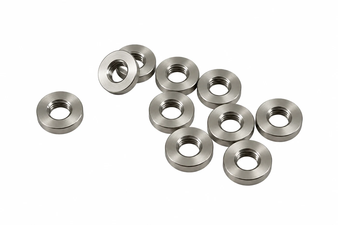
01기능과 광학 정렬
소형 체결부품의 기능과 설계 요구
광학기기용 정밀부품의 역할은 광학 요소와 지지 구조 사이에서 힘과 위치 관계를 안정적으로 전달하는 것입니다. 조립체를 고정하는 힘이 충분해도 접촉면이 기울거나 잠금 과정에서 위치가 변하면 광학 정렬은 달라질 수 있습니다. 설계의 출발점은 외형 치수 자체보다 하중이 흐르는 경로와 움직임을 제한하는 기준입니다.
소형 암나사 부품에서는 나사 결합, 몸체 강성, 안착면이 하나의 구조로 작용합니다. 나사는 축 방향 힘을 전달하고 접촉면은 그 힘을 상대 구조에 분산합니다. 몸체가 얇거나 지지 폭이 좁으면 나사 치수가 정상이어도 국부 굽힘과 면 눌림이 전체 거동을 지배할 수 있습니다.
| 기능 요구 | 설계에서 연결할 관계 | 검증할 결과 |
|---|---|---|
| 위치 유지 | 기준면·위치 결정 형상·잠금 방향 | 체결 전후 이동과 기울기 |
| 하중 전달 | 나사 물림·접촉 폭·몸체 강성 | 분리·미끄럼·영구변형 |
| 반복 조립 | 마찰·안착면·공구 접근 | 위치 복귀와 접촉 상태 변화 |
| 환경 안정성 | 열팽창·구속·오염 경로 | 온도 변화와 사용 이력 후 안정성 |
위치를 정하는 면과 힘을 전달하는 면
위치를 정하는 형상과 체결력을 전달하는 형상을 먼저 구분합니다. 정밀한 어깨면이나 끼워맞춤이 위치를 정하는 구조에서는 나사에 같은 위치 결정 기능을 중복해서 요구하지 않습니다. 반대로 나사축의 자세가 조립에 직접 영향을 주면 나사축과 안착면의 관계를 기능공차로 관리해야 합니다.
좋은 설계 기준은 단품 치수, 체결 조건과 조립 성능을 연결합니다. 중요 특성은 광학 민감도에 따라 선별하고, 가공과 검사에서 같은 기능 기준을 유지합니다. 모든 면에 엄격한 공차를 일괄 적용하기보다 성능에 영향을 주는 관계를 명확히 지정하는 것이 효과적입니다.
기준면과 광학 정렬
초정밀 광학기기는 기계적 위치 변화가 빛의 경로, 초점 또는 검출 위치에 영향을 줄 수 있습니다. 다만 장비가 초정밀이라는 사실이 모든 금속 부품에 동일한 나노미터 공차를 요구한다는 뜻은 아닙니다. 각 부품이 광학 성능에 미치는 민감도와 조립 중 조정 가능 범위를 먼저 나눠야 합니다.
체결 경로와 기준의 분리
평평한 한쪽 면이 조립체에 안착한다면 그 면을 기능 기준으로 검토하고, 나사가 힘만 전달하는지 중심 위치도 정하는지 확인합니다. 일반적인 나사 틈새는 정밀한 위치 결정 수단과 같지 않습니다. 핀·정밀 끼워맞춤·어깨면으로 위치를 정하고 나사로 고정하는 구조라면 각각에 맞는 공차를 배분합니다.
두께는 두 면 사이의 거리이고, 평면도는 한 면 자체의 형상이며, 평행도는 기준면에 대한 반대 면의 방향 관계입니다. 두께 한 점이 합격했다고 양면이 평행하거나 조립체가 기울지 않는다고 판단할 수 없습니다. 나사축의 기울기까지 기능에 영향을 준다면 실제 접촉면과 축의 관계를 도면으로 지정해야 합니다.
| 기능 | 우선 확인할 관계 | 조립에서 볼 결과 |
|---|---|---|
| 높이 설정 | 두께와 양면 접촉 상태 | 초기 위치와 재조립 높이 |
| 누름·고정 | 접촉 영역과 하중 경로 | 국부 눌림·들림·잠금 전후 변화 |
| 중심 유지 | 위치 결정 형상과 나사축 | 편심·측면 이동·상대물 간섭 |
| 반복 분해·조립 | 안착면과 체결 절차 | 반복성·입자 발생·마모 |
작은 높이 차의 의미
지지점 사이의 높이 차가 같아도 지지 간격이 짧아지면 조립체의 기울기는 커집니다. 또한 나사축과 실제 하중 중심이 어긋나면 체결력이 굽힘 모멘트를 만듭니다. 높이와 외경을 각각 검사하는 것만으로 이 효과를 설명할 수 없으므로 접촉 위치·평행 관계·하중 중심을 함께 확인합니다.
Chase와 Burge의 광학 마운트 연구는 접촉 형상이 위치 정확도와 접촉 응력을 함께 바꾼다는 점을 보여 줍니다. 이 원리는 렌즈를 직접 지지하는 면뿐 아니라 광학계에 연결된 기계적 지지 경로를 검토할 때도 중요합니다. 단품의 형상 검사와 조립체의 광학 검증은 서로 다른 결과를 확인하므로 별도로 설계합니다.
02짧은 나사와 체결
짧은 나사와 유효 물림 길이
짧은 암나사에서 중요한 것은 완전한 나사산이 상대 나사와 실제로 겹치는 축 방향 길이입니다. 부품 전체 두께, 가공된 나사 구간과 조립 후 물림 길이는 서로 다를 수 있습니다. 입구·출구의 모따기와 불완전산, 상대 나사의 선단 형상이 실제 하중 지지 구간을 바꿉니다.
두께와 완전산 길이의 차이
유효 물림을 검토할 때는 완전한 산 측면끼리 접촉하는 구간을 기준으로 봅니다. 나사 선단이 관통했다고 부품의 전체 두께가 하중을 지지하는 것은 아닙니다. 반대로 외부로 돌출된 나사 길이가 길어도 내부에서 실제로 겹치는 산의 구간이 늘지 않으면 암나사의 지지 능력은 개선되지 않습니다.
| 형상·조립 조건 | 물림에 미치는 영향 | 설계·검사 대응 |
|---|---|---|
| 입구·출구 모따기 | 완전산이 존재하는 길이 감소 | 모따기 단면과 최종 나사 구간 확인 |
| 상대 나사의 선단 | 진입 길이와 완전산 물림의 차이 | 상대 나사 형상과 조립 깊이 대조 |
| 부분 진입·뒤쪽 간섭 | 안착 전에 토크가 상승할 가능성 | 실제 접촉면과 관통 뒤 공간 확인 |
| 얇은 주변 몸체 | 산 파손과 몸체 변형의 결합 | 접촉 폭·강성·하중 경로 검토 |
나사산이 하중을 균일하게 나누어 받는다고 가정하면 국부 응력을 과소평가할 수 있습니다. 결합부의 변형 적합성과 나사산 강성이 하중 분포에 영향을 주기 때문입니다. 물림 길이만 늘리는 판단에 앞서 양쪽 재료의 강도, 주변 몸체의 팽창·굽힘과 반복 체결에 따른 손상을 함께 검토합니다.
강도와 조립 공간의 동시 검토
나사 체결부는 볼트의 인장 파손뿐 아니라 암나사산의 전단 파손, 얇은 몸체의 변형, 접촉면 눌림을 검토합니다. 필요한 물림 길이는 양쪽 재료의 강도와 나사 공차, 몸체 형상, 하중 및 반복 사용에 따라 달라집니다. NASA의 체결 설계 자료도 완전산의 결합과 나사산 파손을 구분하며, 모든 재질에 한 가지 물림 길이 비율을 적용하지 않습니다.
물림이 부족하면 부품 두께나 국부 보스, 상대 체결 구조를 바꾸는 방안을 검토할 수 있습니다. 더 긴 나사를 쓰는 것만으로 얇은 암나사의 유효 길이가 늘지는 않습니다. 오히려 뒤쪽 광학부·가동부와 간섭하거나 상대 부품을 끝단으로 밀 수 있으므로 관통 뒤 공간도 함께 확인합니다.
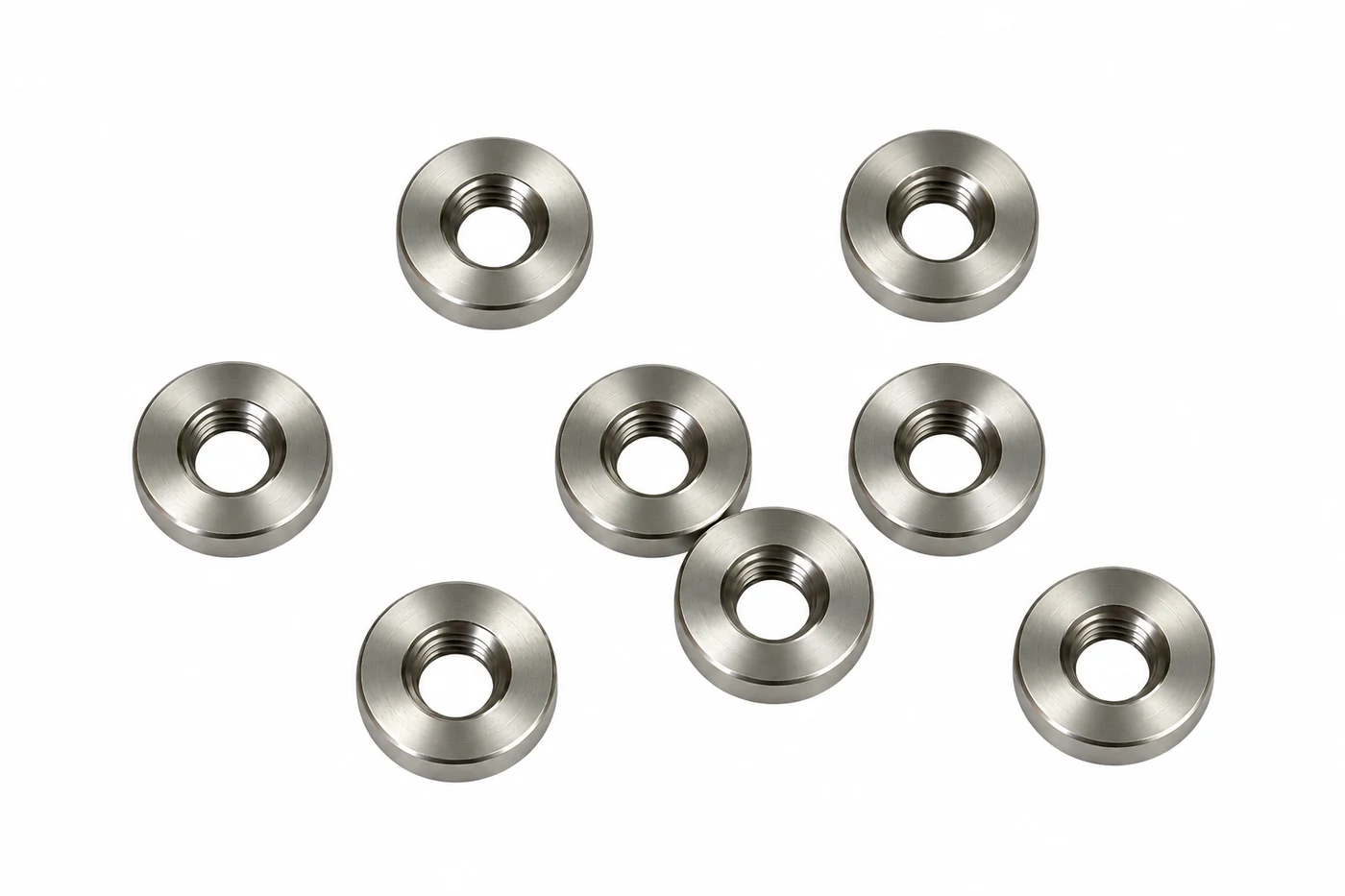
체결 토크와 변형의 균형
체결 토크는 공구가 가하는 회전 작용이고, 예압은 조립체를 누르는 축 방향 힘입니다. 토크의 상당 부분은 나사면과 접촉면의 마찰에 쓰이므로 같은 토크가 항상 같은 예압을 만들지는 않습니다. 세척 상태, 윤활, 표면처리와 반복 체결에 따른 마찰 변화가 작은 부품에서도 영향을 줍니다.
토크 숫자 앞에 필요한 조건
나사 호칭만으로 체결 토크를 정할 수는 없습니다. 일반 볼트의 강도 등급별 토크표는 얇은 특수 암나사의 파손 한계나 광학 허용 변형을 대신하지 못합니다. 상대 나사·부품 재질·유효 물림·접촉 면적·사용 하중을 정한 뒤 필요한 예압과 허용 변형이 동시에 만족되는 범위를 검증합니다.
| 체결 상태 | 생길 수 있는 문제 | 확인할 증거 |
|---|---|---|
| 예압 부족 | 미끄럼·분리·위치 복귀 불량 | 잠금 전후 위치와 외력 후 잔류 변화 |
| 과도한 예압 | 암나사산 손상·면 눌림·몸체 휨 | 분해 후 형상, 체결 곡선과 재검사 |
| 마찰 증가·걸림 | 토크만 상승하고 안착되지 않음 | 접촉면 틈새, 나사 이물과 손상 |
| 마찰 저하 | 동일 토크에서 예압 증가 가능 | 윤활·코팅·세척 조건의 변경 이력 |
얇은 원형 부품을 가장자리 일부만 집어 고정하면 체결 중 기울어지거나 외곽이 변형될 수 있습니다. 조립 도구는 기능면을 찍거나 광학부에 미끄러져 닿지 않도록 맞춰야 합니다. 반복적으로 같은 손힘을 주었다는 설명보다 지정 공구·체결 순서·상대물 조건을 기록하는 편이 재현성을 높입니다.
고정력과 광학 성능의 별도 확인
Thorlabs의 광학 마운트 기술자료는 체결 조건을 바꾸면서 파면 변형과 유지력을 각각 시험합니다. 이는 고정력이 충분한지와 광학 성능이 유지되는지를 서로 다른 시험 결과로 확인하는 접근입니다. 시험 조건은 해당 조립체의 접촉 방식과 강성에 맞춰 정하고, 다른 제품의 토크 값을 그대로 옮기지 않습니다.
실제 조립 검증에서는 승인된 조건으로 체결한 뒤 위치·기울기 또는 장비의 관련 광학 지표를 측정합니다. 해제 후 재조립, 지정 온도 변화, 필요한 외력 시험을 통해 초기 값과 복귀 값을 비교합니다. 조임을 더 강하게 하는 대신 접촉면·하중 경로·구조 강성을 수정해야 하는 경우를 이렇게 구분할 수 있습니다.
03소재와 제작 공정
소재와 열적 안정성
광학기기용 정밀부품의 소재는 절삭성만으로 선택하지 않습니다. 상대 부품과의 열팽창 차이, 요구 강도, 부식 환경, 마찰과 응착, 자기적 요구를 함께 비교합니다. 같은 합금 계열에서도 열처리와 공급 상태가 강도·잔류응력·가공 거동을 바꾸므로 소재 문서와 공정 조건을 연결해야 합니다.
| 선택 기준 | 설계·제작에 미치는 영향 | 확인 자료 |
|---|---|---|
| 강도·연성·경도 | 암나사 파손, 성형 탭 적용, 면 눌림 | 강종·열처리·소재 상태 |
| 열팽창과 열전도 | 상대 이동, 온도 구배, 안정화 시간 | 실제 사용 온도 구간의 물성 |
| 마찰·내식성 | 체결 반복성, 응착과 세척 적합성 | 상대 소재·윤활·후처리 조건 |
| 자기·진공·청정 요구 | 장비 환경과의 적합성 | 요구치와 검증 방법의 명시 |
작은 부품과 긴 조립 경로
균일한 온도 변화에서 자유 열팽창은 재료의 선팽창계수, 기준 길이와 온도 변화의 곱에 비례합니다. 같은 소재라도 연결 경로가 길면 위치 변화가 더 크게 누적됩니다. 정렬을 평가할 때는 작은 체결부만 떼어 보기보다 지지대·하우징·기준면을 잇는 전체 치수 경로를 따라가야 합니다.
작은 부품 자체의 팽창이 작아도 연결된 지지대와 하우징의 길이가 길면 상대 위치 변화는 커질 수 있습니다. 반대로 온도가 서로 다른 지지점이나 다른 재질이 강하게 구속된 구조에서는 단순한 길이 변화가 접촉력·기울기 변화로 나타납니다. 재료를 하나 바꾸는 결정은 조립 경로 전체를 기준으로 검토해야 합니다.
온도와 측정 기준
치수의 국제적인 기준 온도는 일반적으로 20°C입니다. 이는 모든 부품을 정확히 20.000°C에서만 검사해야 한다는 뜻이 아니라, 치수 비교와 필요한 온도 보정을 같은 기준으로 연결한다는 뜻입니다. 허용공차에 비해 온도 영향이 큰 경우에는 부품과 측정기의 실제 온도, 안정화 상태 및 보정 불확도를 기록합니다.
NIST의 온도·치수 연구는 공기 온도와 물체 온도가 같다고 가정할 수 없다는 점을 다룹니다. 손으로 오래 잡은 작은 부품을 곧바로 측정하거나, 세척·건조 직후 측정하면 온도 이력이 섞일 수 있습니다. 일정 시간이라는 형식적 규칙보다 실제 측정값이 안정되는지와 요구 불확도를 함께 확인하는 것이 유효합니다.
소형 부품의 공정 설계와 고정
소형 부품은 완성 형상으로 분리된 뒤 잡을 면이 적고 고정 변형의 영향을 받기 쉽습니다. 공정 순서는 형상을 만드는 순서와 충분한 소재 강성·고정 길이를 남기는 순서를 함께 계획해야 합니다. 회전 대칭 외곽과 축 방향 구멍을 가진 형상에서는 같은 기준으로 가공할 수 있는 면을 묶고, 분리 뒤 재고정할 기능면을 미리 정합니다.
분리 전후의 기준 유지
봉재에서 제작한다면 단면·외경·중앙 구멍을 같은 기준으로 가공하고, 나사와 모따기를 만든 뒤 분리하는 경로를 검토할 수 있습니다. 이 경우 나사 가공 깊이, 절단 위치와 완성 두께가 연결됩니다. 반대 면에 남는 절단 흔적과 버는 후속 고정에서 제거하고 최종 두께·양면 관계를 확인해야 합니다.
먼저 얇은 블랭크를 만든 뒤 가공하는 경우에는 지지면과 회전 방지 구조가 필요합니다. 중앙 구멍 아래에는 탭과 칩이 빠져나갈 공간을 두되, 부품을 누르는 영역은 충분히 받쳐야 합니다. 편의를 위해 강하게 물리는 방식은 검사 때 고정을 풀면 달라지는 형상을 만들 수 있습니다.
| 공정 단계 | 남겨야 할 기준·여유 | 다음 단계 전 확인 |
|---|---|---|
| 소재 준비 | 강종·로트와 충분한 고정 길이 | 소재 증빙, 초기 형상과 표면 |
| 단면·외경·구멍 | 서로의 축·면 관계 | 가공 여유, 구멍 위치와 입구 상태 |
| 나사 가공 | 진입·관통 공간과 지지 | 나사 형상, 칩과 공구 이상 |
| 분리·반대 면 정리 | 완성 두께와 기능 접촉면 | 버·면 손상·변형·재고정 영향 |
| 최종 세척·검사 | 완성 상태와 개별 식별 | 치수·게이지·포장 기록 |
가공 상태와 자유 상태
고정 중에 측정한 외경과 고정을 푼 뒤의 외경은 구분해야 합니다. 얇은 링을 작은 접촉점으로 과하게 물리면 원형도나 면 기울기가 달라질 수 있습니다. 초기품에서는 고정력과 지지 방식을 바꾸며 해제 후 형상을 비교해, 미끄러지지 않으면서 필요한 형상을 유지하는 조건을 찾습니다.
지그는 수량만으로 판단할 항목이 아닙니다. 수작업 고정으로 생기는 찍힘과 재측정 비용이 크면 적절한 받침·포켓·소프트 조가 공정 안정성을 높일 수 있습니다. 고정 장치는 미끄럼을 막는 기능과 기능면을 보호하는 기능을 동시에 만족해야 하며, 반복 안착 때의 기준 재현성도 확인합니다.
04나사 가공과 공정 제어
절삭 탭·성형 탭·나사 밀링
작은 암나사를 만드는 방법은 절삭 탭 하나로 고정되지 않습니다. 절삭 탭은 재료를 칩으로 제거하고, 성형 탭은 연성 재료를 밀어 나사 형상을 만들며, 나사 밀링은 작은 회전 공구를 나선 경로로 이동시킵니다. 세 방법은 필요한 구멍 크기와 부하, 칩, 형상 보정 방식이 다릅니다.
| 방식 | 공정의 특징 | 소형·박육 형상에서의 검토 |
|---|---|---|
| 절삭 탭 | 재료를 제거해 나사 형성 | 칩 배출·역회전·공구 파손·완전산 확보 |
| 성형 탭 | 연성 재료의 소성유동 이용 | 밑구멍·성형 부하·몸체 변형·윤활 |
| 나사 밀링 | 회전 공구와 나선 경로의 조합 | 공구 강성·런아웃·진입 간섭·경로 보정 |
| 구조 변경 | 가공과 조립의 원인 자체 개선 | 지지 폭·보스·체결 구조와 공간의 절충 |
성형 탭의 밑구멍과 외곽
성형 탭은 절삭 탭용 밑구멍을 그대로 사용하면 안 됩니다. 재료가 나사산으로 이동하는 양을 고려해 더 적합한 밑구멍을 정해야 하며, 구멍이 작으면 부하와 충만도가 지나치게 높아질 수 있습니다. 구멍이 크면 충분한 나사산이 형성되지 않을 수 있으므로 제조사 조건과 최종 형상을 함께 확인합니다.
얇고 작은 원형 부품에서는 나사 합격 여부와 함께 가공 뒤 외경·평면·두께의 변화를 확인합니다. 성형 공정의 반경 방향 하중과 소성유동은 주변 몸체에도 작용하기 때문입니다. 얇은 소재용 전용 공구라도 실제 재료의 연성, 지지 방식과 밑구멍 조건을 검증한 뒤 적용해야 합니다.
미세 나사 밀링에서의 공구 처짐
Araujo와 Fromentin의 미세 나사 밀링 연구는 공구와 구멍 사이의 여유가 작을 때 진입 경로가 절삭력과 가공 형상에 미치는 영향을 분석합니다. 공구가 진입하면서 순간적으로 물리는 재료의 양이 달라지고, 작은 공구의 처짐은 프로그램 경로와 실제 절삭 위치의 차이로 이어질 수 있습니다.
공구가 구멍에 들어간다는 사실만으로 안정된 나사 밀링이 보장되지는 않습니다. 공구 목·날의 간섭, 런아웃, 진입·이탈 경로와 보정 방향을 구분해 확인합니다. 공정 조건을 바꾼 뒤에는 나사 게이지 결과와 입구·출구 형상을 함께 비교해 보정이 다른 구간의 결함으로 이동하지 않았는지 검증합니다.
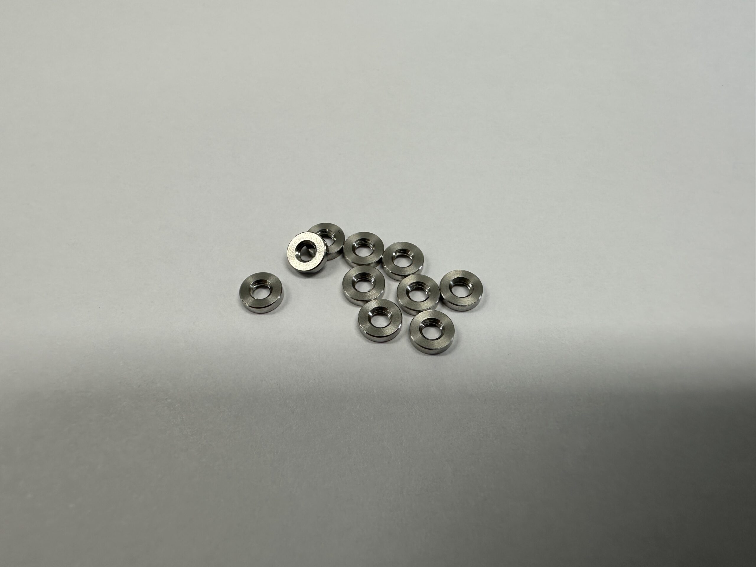
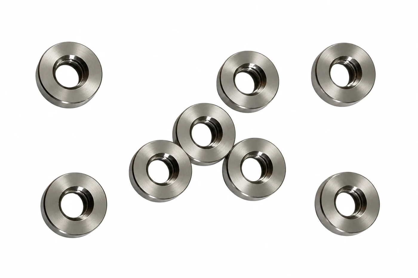
실제 제품을 직접 촬영한 실사진입니다.
소형 암나사의 공정 제어
소형 탭 가공에서는 밑구멍과 공구 축의 일치, 피치에 맞는 회전·이송 동기, 절삭부의 충분한 통과가 연결됩니다. 작은 공구는 휨과 비틀림에 여유가 적으므로 편심·칩 끼임·동기 오차를 한꺼번에 토크 증가로만 해석하지 않아야 합니다. 정회전 진입뿐 아니라 역회전 이탈도 가공 품질에 영향을 줍니다.
밑구멍과 통과 여유
밑구멍은 나사 호칭만으로 정하는 단순 준비 치수가 아닙니다. 절삭 탭에서는 제거할 재료량과 완성 작은지름에 영향을 주고, 성형 탭에서는 산으로 이동하는 재료량과 성형 부하에 영향을 줍니다. 공구 제조사가 제시한 적용 범위 안에서 실제 재료·구멍 품질·요구 공차를 연결해 결정합니다.
탭 선단은 여러 산에 걸쳐 점차 절삭하는 구간을 가집니다. 선단이 부품 아래로 조금 나왔다고 두께 전체에 완전산이 만들어졌다고 볼 수 없습니다. 반대로 통과 거리를 과하게 늘리면 지그와 충돌하므로 실제 공구 형상, 소재 두께, 지그 밑 공간과 칩 배출 경로로 스트로크를 정합니다.
| 관리 항목 | 변화가 나타나는 경로 | 확인·조정 방향 |
|---|---|---|
| 밑구멍 크기·위치 | 절삭량, 부하와 축 어긋남 | 가공 전 구멍과 기준 축 확인 |
| 스핀들·이송 동기 | 산 측면 압박과 축 방향 힘 | 피치 설정, 진입·역회전과 홀더 확인 |
| 칩과 윤활 | 마찰 상승·재절삭·날 손상 | 배출 방향, 지그 공간과 공급 상태 |
| 공구 마모·깨짐 | 토크 패턴과 나사 표면 변화 | 공구 관찰과 직전·직후품 재검사 |
| 고정·지지 | 부품 회전·들림·변형 | 고정 상태와 해제 후 형상 비교 |
이상 신호의 원인 분리
EMUGE의 동기 탭 홀더 설명은 작은 피치 추종 오차와 역회전 때의 축 방향 힘을 다룹니다. YAMAWA의 관통 탭 자료는 칩이 충분히 분리되지 않은 상태에서 역회전하면 공구 손상으로 이어질 수 있음을 설명합니다. 따라서 부하가 상승하면 속도를 임의로 낮추기 전에 동기·칩·밑구멍·고정을 순서대로 구분합니다.
장비가 토크나 부하 이력을 제공한다면 정상 초기품의 진입·가공·이탈 패턴과 비교할 수 있습니다. 다만 장비 신호는 나사 치수와 강도를 직접 측정한 값이 아닙니다. 이상 부품은 분리하고 게이지·확대 관찰·치수 결과를 연결한 뒤 재가공 또는 폐기 판단을 내려야 합니다.
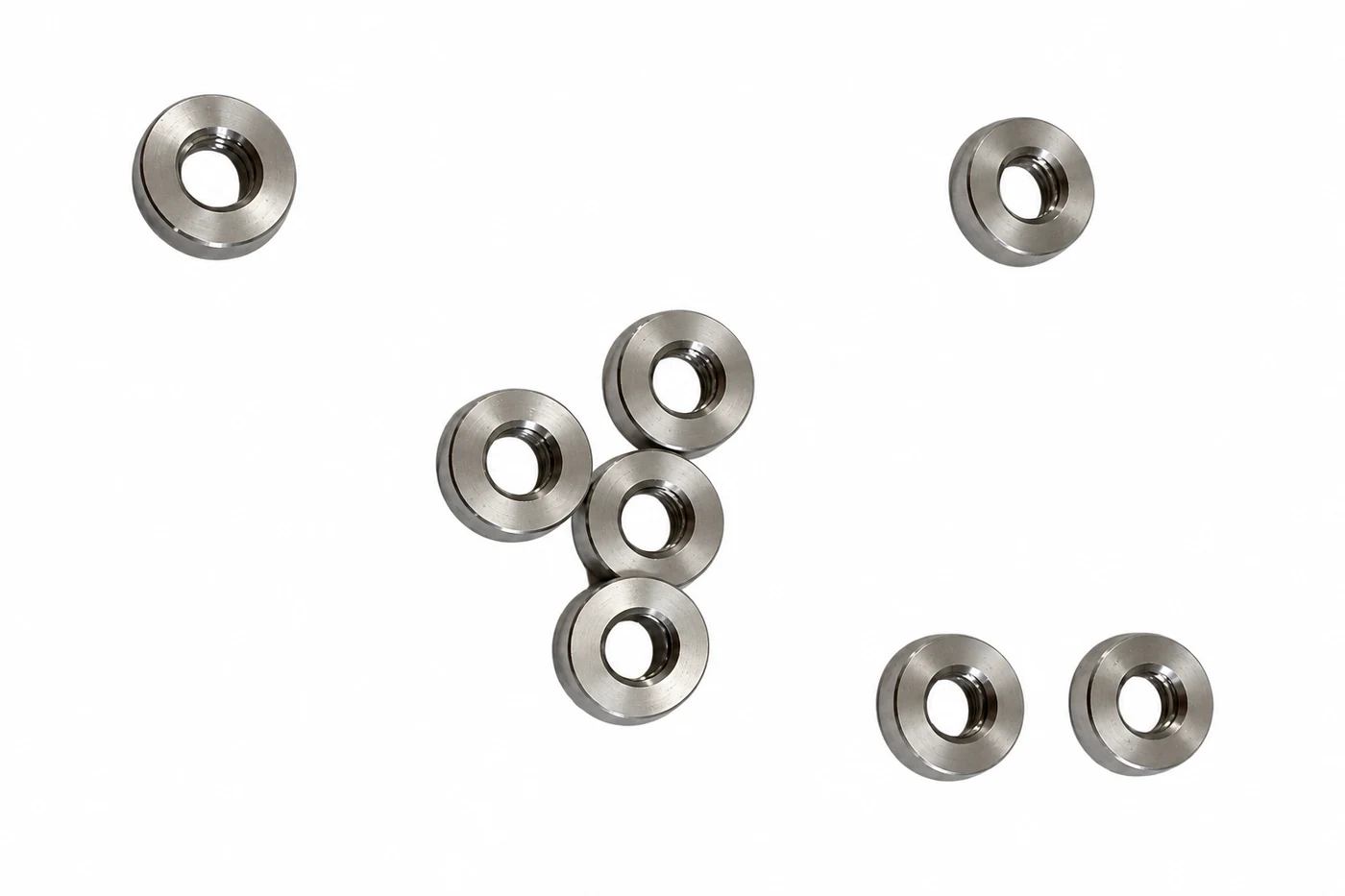
05표면과 청정 환경
접촉면·모서리·표면 건전성
얇은 나사 부품의 품질은 구멍 안에서 끝나지 않습니다. 접촉면의 돌출 버는 조립 높이를 바꾸고, 외곽의 눌림은 안착을 방해하며, 입구 모따기를 과하게 키우면 완전산 구간이 줄어듭니다. 손으로 만졌을 때 매끄럽다는 감각과 기능면의 요구가 같지는 않습니다.
버 제거와 형상 보존
절단·구멍 가공·나사 가공 뒤에는 입구와 출구를 각각 확인합니다. 나사 시작부에 접힌 얇은 금속 조각이 남으면 조립할 때 떨어지거나 나사면 사이에 끼일 수 있습니다. 버를 제거하는 작업은 필요한 모따기·날끝·접촉 면적을 남기면서 수행해야 합니다.
광학 마운트 인터페이스 연구는 모서리를 둥글게 정리하는 행위 자체가 접촉 위치를 바꿀 수 있음을 보여 줍니다. 기능면과 비기능 외곽을 구분하고, 전면에 같은 강도의 연마를 적용하지 않는 편이 합리적입니다. 일괄 연마를 적용한다면 처리 전후 두께·모서리·나사 게이지 결과를 비교해야 합니다.
| 표면 특성 | 외관과 구분할 기능 요구 | 필요한 확인 |
|---|---|---|
| 단면의 가공 무늬 | 거칠기·평면도·접촉 상태 | 지정 위치·평가 조건의 측정 |
| 나사 입구 | 완전산·모따기·초기 결합 | 입구 형상과 나사 게이지 |
| 외곽 모서리 | 버·눌림·간섭 방지 | 배율·조명을 정한 양면 관찰 |
| 피막과 광택 | 마찰·청정·접촉 치수 | 후처리 이력과 최종 상태 검사 |
거칠기와 광학면의 구분
광학기기에 쓰이는 기계 접촉면과 렌즈·반사경의 광학면은 서로 다른 기준으로 평가합니다. 기계 접촉면에서는 안착과 하중 전달에 필요한 거칠기·형상을 보고, 광학면에서는 파면과 산란에 영향을 주는 형상을 봅니다. 광로에 노출되는 금속면은 빛의 파장·입사 방향·주변 구조에 맞춰 반사와 산란 대책을 별도로 정합니다.
작은 환형 면에서 거칠기를 측정할 때는 측정 길이와 방향, 모서리·구멍을 피할 공간을 먼저 확보해야 합니다. 평가 길이가 부족한 위치에 일반적인 설정을 그대로 적용하면 비교 가능한 결과가 나오지 않을 수 있습니다. 도면에는 필요한 표면 항목과 위치를 정하고, 측정 방법은 실제 접근성에 맞춰 합의합니다.
세척·표면처리·사용 환경
가공이 끝난 뒤 남는 절삭유와 금속 입자는 서로 다른 오염입니다. 입자를 제거했어도 얇은 유막이 남을 수 있고, 광택이 좋아도 나사 골에 세정액이나 이물이 남을 수 있습니다. 최종 품질은 소재·후처리에 맞는 세척, 헹굼, 건조와 재오염 방지까지 연결해야 합니다.
작은 부품의 회수와 포장
소형 부품은 세척 중 유실되거나 서로 부딪히기 쉽습니다. 적합한 바스켓이나 구획을 사용하되 그 망·포켓 자체가 입자를 만들거나 세척액의 흐름을 막지 않는지 확인합니다. 작은 암나사 구간까지 헹굼과 건조가 되는지, 세척 후에도 게이지 통과와 기능면 상태가 유지되는지 검증합니다.
초음파 세척의 시간·출력·용액을 모든 재질에 똑같이 적용할 수는 없습니다. 모서리 손상, 잔사, 부식과 코팅 변화가 없는 조건을 정해야 합니다. 건조 후에는 취급 도구와 포장재가 남기는 섬유·가소제·마찰 입자까지 고려하고, 소량품은 혼입과 수량 오류를 막을 개별 구획을 활용할 수 있습니다.
도금 후 나사와 진공 조건
나사면에 코팅을 추가하면 처리 전 게이지 합격만으로 최종 적합성을 판단할 수 없습니다. 미터 나사의 경사진 산 측면에 피막이 쌓이면 단순한 반경 증가보다 유효지름 변화가 커질 수 있습니다. YAMAWA의 기술자료가 설명하는 피막과 나사 형상의 관계를 바탕으로 도금 분포·마스킹·처리 여유를 검토하고, 최종 상태에서 게이지와 체결 특성을 다시 확인합니다.
| 사용 조건 | 추가로 정할 요구 | 납품 확인 |
|---|---|---|
| 일반 연구 장비 내부 | 입자·유막과 조립 적합성 | 세척 상태, 나사와 접촉면 |
| 광로 주변 | 입자 이동·반사·휘발 성분 | 장비의 오염·산란 요구 |
| 진공 사용이 지정된 경우 | 가스 방출·갇힌 공간·재료 적합성 | 세척·건조·필요한 베이크 조건 |
| 도금·코팅이 지정된 경우 | 치수 변화·피막 잔사·마찰 변화 | 최종 나사·두께·체결 검증 |
진공 조건에서는 나사와 맞닿은 구조에 갇힌 기체가 남는지, 윤활제·접착제·포장재가 사용 압력과 온도에 적합한지 검토합니다. 막힌 틈새의 배기 경로와 재료의 가스 방출은 표면 입자와 다른 관리 항목입니다. Thorlabs의 진공 부품 자료처럼 재질·배기·세척·포장을 하나의 사용 조건으로 연결해야 합니다.
세척과 코팅은 체결 마찰도 바꿀 수 있습니다. 따라서 승인된 가공품을 마지막에 다른 용액으로 세척하거나 다른 피막으로 바꾼 경우에는 치수뿐 아니라 조립 조건까지 다시 확인합니다. 외관 개선 작업을 기능과 무관한 마지막 단계로 취급하지 않는 것이 중요합니다.
06치수·나사 검사
소형 부품의 치수 측정
작은 부품은 측정기 눈금이 충분히 촘촘한지만 보고 검사 방법을 정할 수 없습니다. 부품을 어떻게 받치는지, 측정자가 어느 면을 얼마나 누르는지, 구멍과 모따기를 피할 수 있는지가 결과를 바꿉니다. 한 번의 표시값보다 반복 안착과 측정 위치 변화까지 포함한 측정 체계를 확인해야 합니다.
| 특성 | 검토할 측정 방법 | 결과를 바꾸는 조건 |
|---|---|---|
| 외경과 외곽 | 비접촉 영상 또는 적합한 접촉 측정 | 초점·조명·측정 방향·모서리 인식 |
| 두께 | 저측정력 접촉 측정 등 | 측정면 크기·구멍·모따기·지지 |
| 양면 형상·평행 관계 | 기준을 설정한 높이·형상 측정 | 고정 변형·샘플링 위치·정렬 |
| 암나사 | 규격에 맞는 게이지와 보완 검사 | 피치·공차·짧은 길이·청정 상태 |
| 버·입구 형상 | 확대 관찰 또는 적합한 광학 측정 | 배율·조명·시야와 사각 영역 |
영상과 접촉 측정의 역할
상부에서 본 구멍의 영상은 보이는 경계를 측정합니다. 그 경계가 모따기의 큰 지름인지, 입구의 작은 지름인지, 내부 나사 골의 일부인지 구분해야 합니다. 나사 유효지름과 산 측면 전체를 일반적인 상부 영상 하나로 확인할 수는 없습니다.
반사되는 작은 금속면은 조명 방향에 따라 경계 위치가 달라 보일 수 있습니다. ZEISS의 영상 측정 자료도 반사면과 어려운 모서리에 맞는 조명 선택을 별도로 다룹니다. 실제 검사에서는 배율·초점·조명·경계 추출 조건을 고정하고, 교정된 기준과 반복 측정으로 적합성을 확인합니다.
불확도와 합격 판정
표시 분해능, 반복성, 측정불확도는 같은 뜻이 아닙니다. NIST의 소형 부품 측정 자료는 장비뿐 아니라 환경·셋업·측정 위치가 불확도에 기여한다고 설명합니다. BIPM의 적합성 평가 지침에 따라 공차 한계 근처에서는 측정불확도를 어떻게 판정에 반영할지 발주자와 제조자가 먼저 합의하는 것이 좋습니다.
측정값이 공차 안에 있어도 불확도 구간이 공차 경계를 넘을 수 있습니다. 이때 합격 여부는 사전에 정한 판정 규칙에 따라 달라집니다. 불확도 구간 전체가 공차 안에 있어야 한다는 규칙을 채택하면 경계 근처의 결과를 그대로 합격 처리할 수 없으며, 재측정·측정법 개선 또는 합의된 처리 절차가 필요합니다.
검사성적서에는 최종 값과 함께 적용 도면, 측정기·게이지 식별, 필요한 측정 조건과 판정 규칙을 연결합니다. 제한된 측정 자료만으로 장기간의 공정능력이나 모든 재제작품의 성능을 보증하지 않습니다. 부품별 중요 특성과 이상 이력을 추적하고, 검사 범위를 바꿀 때는 그 근거를 기록합니다.
짧은 암나사의 게이지 검사
실제 볼트가 들어간다는 사실은 호환성을 보는 간단한 확인일 뿐, 규정된 나사 검사를 대신하지 못합니다. 볼트 자체의 치수·마모·표면 상태가 다르기 때문입니다. 피치와 공차 등급에 맞는 GO·NOT GO 나사 플러그 게이지를 사용하고, 요구되는 작은지름 검사를 구분해야 합니다.
GO와 NOT GO의 다른 역할
GO 게이지는 여러 형상 오차가 함께 영향을 주는 기능적인 끼워맞춤을 확인하며, 지정된 유효 나사 구간을 무리한 힘 없이 통과해야 합니다. NOT GO 게이지는 과대한 유효지름 쪽을 확인합니다. 나사 게이지 결과와 작은지름용 원통 플러그 게이지 결과는 같은 검사가 아닙니다.
| 검사 | 주로 확인하는 것 | 짧은 나사에서 주의할 점 |
|---|---|---|
| GO 나사 플러그 | 기능적인 나사 결합과 하한 측 | 필요 구간 전체의 통과, 억지 조임 금지 |
| NOT GO 나사 플러그 | 유효지름 상한 측 | 회전수와 짧은 부품의 관통 여부 |
| 작은지름 검사 | 암나사 안쪽 지름 한계 | 나사 플러그 검사로 대체하지 않음 |
| 확대 관찰 | 찢김·버·입구·출구 형상 | 게이지 합격으로 외관 결함이 사라지지 않음 |
| 상대 부품 조립 | 실제 접근·간섭·안착 | 공차 검사와 별도 기능 확인 |
3산 이하의 관통 판정
ISO 1502 방식에서는 NOT GO 나사 플러그 게이지의 진입을 일반적으로 두 회전 이하로 제한합니다. 여기에 중요한 조건이 있습니다. 나사 길이가 3산 이하인 부품에서는 NOT GO 게이지가 완전히 관통해서는 안 됩니다. 짧은 부품에 ‘두 번까지 돌려도 된다’는 설명만 적용하면 이 조건을 놓칠 수 있습니다.
짧은 나사는 회전수 제한만 기계적으로 적용하기보다 완전산 구간과 관통 여부를 함께 해석해야 합니다. 실제 검사는 모따기와 적용 규격·게이지 형상을 확인한 절차로 수행합니다. 회전수는 규격의 정의에 따라 게이지를 되돌려 빼면서 확인하며, 억지로 밀거나 부품을 변형시키는 힘을 주지 않습니다.
중요 나사 특성의 검사 범위는 기능 위험과 공정 이력을 기준으로 정합니다. 치수 게이지 통과는 나사산의 파손 하중이나 광학 정렬을 보증하지 않습니다. 최종 세척·표면처리 후 상태에서 게이지 검사를 수행하고, 체결 강도나 반복 수명이 요구되면 별도의 시험 조건과 검증 계획을 수립합니다.
07조립 검증과 이력 관리
조립 검증과 불량 원인
광학기기용 정밀부품은 단품이 도면에 맞는지와 장비에서 필요한 상태를 유지하는지를 나눠 확인합니다. 조립 시험에서는 상대 나사·접촉면·공구·체결 순서를 실제 사용 조건에 맞춰야 합니다. 부품 한 개를 교환했을 때만 결과가 바뀌는지, 상대 구조나 작업 순서 때문에 바뀌는지도 구분합니다.
초기 값과 복귀 값
기준 조립 상태에서 위치·기울기 또는 관련 광학 지표를 기록하고, 지정 조건으로 잠근 뒤의 변화를 측정합니다. 필요한 경우 해제·재체결을 반복하고 초기 위치로 얼마나 돌아오는지 확인합니다. 사용 온도 변화 시험을 한다면 가열·냉각 중 값뿐 아니라 기준 온도로 돌아온 뒤의 잔류 변화도 기록합니다.
표면이 한 번 눌려 자리 잡는 현상, 마찰 상태 변화, 나사 손상은 모두 반복성 저하로 보일 수 있습니다. 시험 전후 게이지 검사와 접촉면 관찰을 연결하면 원인을 좁힐 수 있습니다. 현미경 사진 하나나 토크 값 하나만으로 모든 원인을 설명하려고 하지 않습니다.
| 증상 | 가능한 원인 경로 | 우선 확인 |
|---|---|---|
| 일부 부품만 나사가 뻑뻑함 | 버·칩·유효지름·피치 또는 코팅 차이 | 최종 상태 게이지와 양끝 확대 관찰 |
| 조이면 기울거나 높이가 바뀜 | 접촉면 버·비평행·편심 하중 | 기준면, 접촉 위치와 잠금 전후 변위 |
| 해제 뒤 형상이 돌아오지 않음 | 소성변형·산 손상·면 눌림 | 자유 상태 치수와 손상 위치 |
| 반복 체결 후 헐거워짐 | 산 마모·손상·접촉면 자리잡음 | 상대 나사, 반복 횟수와 재검사 |
| 온도 변화 뒤 위치가 남음 | 구속·마찰 미끄럼·조립체 열 이력 | 부품 온도와 복귀 시 잔류 값 |
| 광학부 주변에 입자 발생 | 잔류 칩·접촉 마모·포장재 이물 | 입자 발생 시점과 접촉·포장 경로 |
재가공과 설계 변경의 경계
불량을 만났을 때 재탭이나 연마로 무조건 되살리면 유효지름·완전산 길이·두께가 도면에서 벗어날 수 있습니다. 재가공은 남은 가공 여유와 최종 검사 가능성을 검토하고 승인된 범위에서 수행합니다. 같은 증상이 반복되면 공구 조건뿐 아니라 부품 두께, 접촉면 폭, 지지·체결 구조 자체를 재검토합니다.
검증 보고서에는 합격 여부 외에 변경한 조건과 결과의 인과관계를 남깁니다. 예를 들어 세척 후 조립 토크가 달라졌다면 세척 상태·윤활 유무·상대 나사를 같이 기록합니다. 이 기록은 재제작과 공정 변경에서 동일한 문제의 재발을 줄이고 검증 범위를 정하는 근거가 됩니다.
설계 검증과 공정 이력 관리
광학기기용 정밀부품의 기술 기준은 가공 도면에서 끝나지 않습니다. 기능공차와 조립 조건을 연결하고, 공정 중 달라질 수 있는 소재·공구·지지·후처리를 관리해야 합니다. 개별 검사 결과와 조립 검증을 같은 설계 개정에 연결하면 합격 판정의 근거와 변경 영향을 함께 추적할 수 있습니다.
기능 요구를 검증 항목으로 변환
| 설계 항목 | 연결할 공정 정보 | 검증의 초점 |
|---|---|---|
| 기준면과 축의 관계 | 공정 기준·재고정·측정 정렬 | 단품 자세와 조립 기울기 |
| 나사 결합 | 밑구멍·공구·완전산·게이지 | 기능 결합과 유효지름 한계 |
| 소재와 표면 | 공급 상태·처리·세척 이력 | 변형·마찰·최종 치수 |
| 조립 안정성 | 접촉면·상대물·공구·체결 순서 | 잠금 변화와 반복성 |
| 사용 환경 | 열 이력·오염·필요한 진공 조건 | 성능 유지와 복귀 상태 |
| 변경 관리 | 도면·공정 개정과 승인 이력 | 재검증 항목과 영향 범위 |
설계 검증에서는 치수 적합, 조립 가능성과 사용 성능을 구분해 합격 기준을 정합니다. 나사 게이지 합격만으로 파손 하중을 증명하거나, 초기 광학 정렬만으로 온도 변화 후 안정성을 보증하지 않습니다. 시험이 확인한 특성과 확인하지 않은 특성을 구분해야 과도한 보증과 검증 누락을 함께 줄일 수 있습니다.
개별 이력과 변경 영향
검사 결과는 기능면을 손상시키지 않는 식별 방식과 연결합니다. 소재 로트, 공정·도면 개정, 게이지 식별, 측정 조건과 승인된 예외를 함께 보관하면 재제작 때 달라진 조건을 찾기 쉽습니다. 포장 구획과 관리번호를 활용하면 작은 부품에도 기능면의 임의 타각 없이 추적성을 부여할 수 있습니다.
한계 토크나 파손 시험은 사용품의 비파괴 검사와 다른 검증입니다. 대표 시험편을 사용한다면 소재·몸체 강성·나사·후처리·고정 조건 가운데 실제 부품의 어떤 특성을 재현하는지 명확히 해야 합니다. 시험 결과를 설계 변경에 적용할 때도 변경한 변수와 검증된 범위를 다시 대조합니다.
초정밀 광학기기의 기계적 안정성은 기준면, 체결 하중, 표면 상태와 검증 절차가 일관되게 연결될 때 확보할 수 있습니다. 설계는 필요한 기능을 정의하고, 가공은 그 관계를 구현하며, 검사는 기능에 연결된 증거를 제공합니다. 이 연결을 유지하는 것이 소형 정밀부품의 품질을 설명하는 핵심입니다.
English Technical Overview
The quality of precision components for optical instruments is not determined by shape alone. Datums establish position, threads and contact faces transfer loads, and materials and supports respond to temperature changes. Small movements and deformation along this path affect the stability and repeatability of optical alignment.
Miniature fastening components concentrate several functions within limited contact areas and short threaded regions. Design must connect loads with displacement, machining must preserve references and surfaces, and inspection must distinguish component conformity from assembly performance. The following discussion develops these connections through contact mechanics, threaded joints, process control, cleanliness, measurement uncertainty and assembly verification.
Datums and load paths
Separate location from fastening and examine deformation during locking.
Machining through final surfaces
Connect workholding, cutting, burrs, cleaning and coatings to final function.
Dimensions and assembly performance
Use gauging, measurement uncertainty and repeated assembly for distinct evidence.
01Function and optical alignment
Functions and design requirements of miniature fastening components
Precision components for optical instruments transfer forces and positional relationships between optical elements and their supporting structure. Adequate clamping force does not ensure alignment if contact faces tilt or locking shifts the assembly. Design begins with the load path and the references that constrain motion, rather than external dimensions alone.
In a miniature internally threaded component, the threaded joint, body stiffness and seating faces act as one structure. Threads transfer axial force while contact surfaces distribute it into the mating structure. A thin body or narrow support can allow local bending and indentation to govern behavior even when thread dimensions conform.
| Functional requirement | Design relationships | Result to verify |
|---|---|---|
| Position retention | Datums, locating features and locking direction | Movement and tilt during tightening |
| Load transfer | Engagement, contact width and body stiffness | Separation, slip and permanent deformation |
| Repeated assembly | Friction, seating surfaces and tool access | Position recovery and contact changes |
| Environmental stability | Expansion, constraints and contamination paths | Stability after thermal changes and service history |
Locating surfaces and load-bearing surfaces
First distinguish locating features from features that transfer clamping force. Where a precision shoulder or fit determines position, the thread should not be assigned a redundant locating function without analysis. If the orientation of the thread axis directly affects assembly, control its relationship to the seating face through functional tolerances.
Effective design criteria connect component dimensions, fastening conditions and assembly performance. Select critical characteristics according to optical sensitivity and retain the functional reference system through machining and inspection. Explicitly controlling relationships that affect performance is more effective than assigning equally tight tolerances to every surface.
Datum surfaces and optical alignment
In an ultra-precision optical instrument, mechanical movement can affect the light path, focus or detection position. The instrument’s precision does not mean that every metal component requires the same nanometer tolerance. Each part’s sensitivity to optical performance and the adjustment available during assembly must first be distinguished.
Separate the fastening path from the locating references
If one flat face seats against the assembly, assess that face as a functional reference and determine whether the thread only transfers force or also locates the center. Normal thread clearance is not equivalent to precise location. Where pins, precision fits or shoulders establish position and a screw provides clamping, assign tolerances to those separate functions.
Thickness is the distance between two faces, flatness describes the form of one face, and parallelism describes the orientation of the opposite face relative to a datum. A passing thickness measurement at one point does not establish parallel faces or a tilt-free assembly. If thread-axis inclination matters, specify the relationship between the axis and the actual seating surface.
| Function | Primary relationship | Assembly result to examine |
|---|---|---|
| Setting height | Thickness and contact on both faces | Initial position and reassembly height |
| Clamping | Contact region and load path | Local indentation, lifting and movement during locking |
| Maintaining center position | Locating features and thread axis | Eccentricity, lateral movement and interference |
| Repeated disassembly | Seating surfaces and fastening procedure | Repeatability, particles and wear |
The significance of a small height difference
For the same height difference, a shorter support span produces greater tilt. Offset between the thread axis and the actual load center also turns clamping force into a bending moment. Separate height and diameter checks cannot fully describe these effects; contact positions, parallelism and the load center must be assessed together.
Chase and Burge’s optical-mount research shows that contact geometry affects both positioning accuracy and contact stress. This principle matters when examining mechanical support paths connected to an optical system as well as direct lens interfaces. Component geometry inspection and assembled optical verification address different outcomes and should be planned separately.
02Short threads and fastening
Short threads and effective engagement
For a short internal thread, the important quantity is the axial overlap of fully formed mating threads. Overall thickness, the machined threaded region and assembled engagement can differ. Entry and exit chamfers, incomplete threads and the mating screw tip alter the region that actually supports load.
Thickness versus complete-thread length
Assess engagement from the region where fully formed mating flanks overlap. A screw tip passing through does not mean the entire component thickness supports load. Likewise, greater external screw protrusion does not improve internal-thread support unless the actual engaged region increases.
| Geometry or assembly condition | Effect on engagement | Design and inspection response |
|---|---|---|
| Entry and exit chamfers | Reduced length containing complete threads | Check chamfer sections and the final thread region |
| Mating screw tip | Insertion length differs from complete-thread overlap | Compare screw geometry with assembly depth |
| Partial insertion or rear interference | Torque may rise before seating | Check actual contact faces and through-clearance |
| Thin surrounding body | Thread failure interacts with body deformation | Review contact width, stiffness and load path |
Assuming equal load sharing among threads can underestimate local stress. Deformation compatibility and thread stiffness affect the load distribution. Before simply increasing engagement, review the strengths of both materials, expansion and bending of the surrounding body, and damage from repeated tightening.
Check strength and assembly clearance together
A threaded joint requires consideration of screw tensile failure, internal-thread stripping, deformation of the thin body and indentation of contact surfaces. Required engagement depends on both materials, thread tolerances, body geometry, loads and repeated use. NASA fastening references distinguish complete-thread engagement from stripping resistance rather than applying one engagement ratio to every material.
If engagement is insufficient, consider greater thickness, a local boss or a revised mating fastening arrangement. A longer screw alone does not increase the effective length of a thin internal thread. It may instead interfere with an optical or moving component behind the part or push against it with its tip, so through-clearance must also be checked.
Balancing fastening torque and deformation
Fastening torque is the rotational action applied by the tool; preload is the axial force compressing the assembly. Much of the applied torque overcomes friction at the threads and bearing surfaces, so identical torque does not always produce identical preload. Cleaning, lubrication, surface treatment and repeated tightening can alter friction even in very small components.
Conditions required before assigning torque
Thread designation alone cannot establish tightening torque. General bolt torque charts do not establish the failure limit of a thin custom internal thread or allowable optical distortion. Define the mating screw, materials, effective engagement, contact area and service loads, then validate a range satisfying both required preload and allowable deformation.
| Fastening condition | Potential problem | Evidence to examine |
|---|---|---|
| Insufficient preload | Slip, separation or poor position recovery | Position before/after locking and residual movement after loading |
| Excessive preload | Thread damage, indentation or body bending | Geometry after disassembly, tightening response and reinspection |
| Increased friction or binding | Torque rises without proper seating | Contact gaps, thread contamination and damage |
| Reduced friction | Potentially higher preload at the same torque | Changes in lubrication, coating and cleaning |
Holding a thin circular part at only a small section of its edge can allow tilt or distort its perimeter during tightening. Assembly tools should protect functional faces and avoid slipping into optical elements. Recording the specified tool, sequence and mating conditions provides better reproducibility than describing repeated tightening with the same hand force.
Verify retention and optical performance separately
Thorlabs optical-mount documentation tests wavefront distortion and retention under different fastening conditions. This approach treats adequate retention and preserved optical performance as separate test outcomes. Test conditions must match the assembly’s contact arrangement and stiffness rather than inherit torque values from another product.
Assembly verification measures position, tilt or the relevant optical metric after tightening under approved conditions. Compare initial and recovered values after reassembly, specified temperature changes and any required external-load tests. These results help identify when contact geometry, load paths or structural stiffness need revision instead of simply increasing tightening force.
03Materials and manufacturing
Material selection and thermal stability
Material selection for precision optical-instrument components involves more than machinability. Compare differential expansion, strength, corrosion conditions, friction, galling and magnetic requirements. Even within an alloy family, heat treatment and supply condition alter strength, residual stress and machining behavior, so material documentation must connect to process conditions.
| Selection factor | Design and manufacturing effect | Evidence required |
|---|---|---|
| Strength, ductility and hardness | Thread failure, form-tapping suitability and indentation | Alloy, heat treatment and supply condition |
| Expansion and thermal conductivity | Relative movement, temperature gradients and stabilization | Properties over the actual operating range |
| Friction and corrosion resistance | Fastening repeatability, galling and cleaning compatibility | Mating material, lubrication and finishing conditions |
| Magnetic, vacuum and cleanliness needs | Compatibility with the instrument environment | Explicit requirements and verification methods |
A small component within a long assembly path
Under a uniform temperature change, free thermal expansion is proportional to the expansion coefficient, reference length and temperature change. A longer connected path accumulates more movement even with the same material. Alignment assessment should follow the full dimensional path through supports, housings and reference faces rather than isolate the small fastening component.
A small component may expand little while a long connected support or housing undergoes greater movement. Unequal support temperatures or strongly constrained dissimilar materials can instead convert expansion into changes in contact force or tilt. A material substitution must therefore be evaluated across the complete assembly path.
Temperature and dimensional reference
The international reference temperature for dimensional measurement is generally 20°C. This connects dimensional comparison and necessary temperature correction to a common reference; it does not require every inspection to take place at exactly 20.000°C. Where thermal effects are significant relative to tolerance, record actual part and instrument temperatures, stabilization and correction uncertainty.
NIST research on temperature and dimensional measurement addresses why air temperature cannot automatically be treated as object temperature. Holding a small part for an extended time or measuring immediately after cleaning and drying can introduce thermal-history effects. Actual measurement stability and the required uncertainty are more useful than an arbitrary waiting-time rule alone.
Process planning and workholding for miniature components
Miniature components offer limited gripping area after separation and are sensitive to clamping distortion. Plan both the sequence of generating features and the retention of adequate stock stiffness and gripping length. For rotationally symmetric parts with axial holes, group features that can share a machining reference and define the functional faces used for subsequent setups.
Preserve references before and after separation
For manufacture from bar stock, one possible route machines the face, outside diameter and central hole from a common reference, then threads and chamfers before parting off. Threading depth, cutoff position and final thickness are interdependent. Remaining cutoff marks and burrs on the opposite face require a subsequent setup, followed by checks of thickness and the relationship between the faces.
If thin blanks are prepared first, provide a supporting surface and anti-rotation features. Leave clearance under the central hole for the tap and chips while adequately supporting the clamped region. Excessive clamping for convenience can produce a shape that changes when the part is released for inspection.
| Stage | References and allowances to retain | Check before proceeding |
|---|---|---|
| Stock preparation | Material batch and adequate gripping length | Material documentation, initial form and surface |
| Face, diameter and hole | Mutual axis-to-face relationships | Allowances, hole location and entry condition |
| Threading | Entry and through-clearance with support | Thread form, chips and tool abnormalities |
| Separation and opposite-face finishing | Final thickness and functional contact face | Burrs, damage, distortion and resetting effects |
| Final cleaning and inspection | Finished condition and individual identification | Dimensions, gauging and packaging records |
Machining condition versus free condition
Distinguish diameter measured under clamping from diameter measured after release. Excessive point contact on a thin ring can alter roundness or face inclination. During initial trials, compare released geometry at different clamping forces and support arrangements to find conditions that prevent slip while preserving the required form.
Fixture selection is not determined by quantity alone. Suitable supports, pockets or soft jaws can improve stability when manual gripping causes dents and repeated measurement. Workholding must prevent slip while protecting functional surfaces, and its ability to reproduce references on repeated seating must also be checked.
04Threading and process control
Cutting taps, forming taps and thread milling
A cutting tap is not the only way to produce a small internal thread. Cutting taps remove material as chips, forming taps displace ductile material into the thread profile, and thread milling moves a small rotating cutter along a helical path. Their pilot-hole requirements, loads, chip behavior and dimensional correction methods differ.
| Method | Process principle | Miniature and thin-wall considerations |
|---|---|---|
| Cut tapping | Thread formation by material removal | Chips, reversal, breakage and complete threads |
| Form tapping | Plastic flow of ductile material | Pilot hole, forming load, body distortion and lubrication |
| Thread milling | Rotating cutter following a helical path | Stiffness, runout, entry interference and compensation |
| Structural revision | Address underlying machining and assembly causes | Tradeoffs among support width, bosses, fastening and space |
Pilot holes and body deformation in form tapping
Do not automatically use a cutting-tap pilot hole for a forming tap. Select a suitable hole considering how much material must flow into the thread. An undersized hole can cause excessive load and filling; an oversized hole can leave insufficient thread formation. Check the manufacturer’s conditions together with the final profile.
For a small thin circular part, evaluate changes in outside diameter, face form and thickness alongside thread conformity. Radial forming loads and plastic flow also act on the surrounding body. Even a tool intended for thin stock requires validation of actual material ductility, support and pilot-hole conditions.
Tool deflection in miniature thread milling
Araujo and Fromentin’s miniature thread-milling research examines how entry paths affect cutting forces and geometry when tool-to-hole clearance is small. Entry changes the instantaneous material engagement, and deflection of a small cutter can separate the actual cutting position from the programmed path.
A cutter fitting inside a hole does not by itself establish stable thread milling. Separately check neck and edge interference, runout, entry and exit paths, and compensation direction. After a process change, compare gauging results with entry and exit geometry to ensure the correction has not shifted a defect elsewhere.
Process control for miniature internal threads
Miniature tapping connects hole-to-tool alignment, pitch-matched spindle/feed synchronization and sufficient passage of the cutting lead. Small tools have limited bending and torsional capacity. Eccentricity, trapped chips and synchronization errors should not all be treated as an undifferentiated torque increase. Reverse withdrawal also affects thread quality.
Pilot holes and through-clearance
The pilot hole is more than a preparation dimension selected from thread designation alone. In cut tapping it affects stock removal and the finished minor diameter; in form tapping it affects material flow into the thread and forming load. Select it within the tool manufacturer’s application range while accounting for actual material, hole quality and required tolerances.
A tap’s leading section cuts progressively over several threads. Its tip emerging slightly below the workpiece does not establish complete threads through the entire thickness. Excessive travel, however, can cause a fixture collision. Set the stroke from the actual tool geometry, stock thickness, underside clearance and chip-removal path.
| Control item | Effect pathway | Check or adjustment |
|---|---|---|
| Pilot-hole size and location | Stock removal, load and axis mismatch | Check the hole and reference axis before tapping |
| Spindle/feed synchronization | Thread-flank loading and axial force | Check pitch settings, entry, reversal and holder |
| Chips and lubrication | Friction, recutting and edge damage | Check discharge direction, fixture space and fluid supply |
| Tool wear or chipping | Changed torque patterns and thread surfaces | Inspect the tool and preceding/following parts |
| Clamping and support | Rotation, lifting or distortion | Compare clamped and released geometry |
Separate the causes of abnormal signals
EMUGE’s synchronized tapping-holder documentation addresses small pitch-following errors and axial forces during reversal. YAMAWA’s through-hole tapping guidance explains how reversing before chips separate adequately can damage the tool. When load rises, distinguish synchronization, chips, pilot holes and clamping before arbitrarily reducing speed.
If machine torque or load histories are available, compare entry, cutting and withdrawal patterns against accepted initial parts. These signals do not directly measure thread dimensions or strength. Segregate abnormal parts and combine gauge results, magnified observation and dimensional checks before deciding on rework or rejection.
05Surfaces and cleanliness
Contact faces, edges and surface integrity
The quality of a thin threaded component extends beyond the hole. A raised burr on a contact face changes assembly height; a dented perimeter can prevent seating; an oversized entry chamfer reduces complete-thread length. A smooth feel to the touch is not equivalent to meeting functional-surface requirements.
Remove burrs while preserving geometry
Inspect both entry and exit after cutoff, hole making and threading. A folded metal fragment at the thread start can detach during assembly or become trapped between thread flanks. Deburring must retain the required chamfer, edge geometry and contact area.
Research on optical-mount interfaces shows that rounding an edge can itself move the contact location. Distinguish functional surfaces from nonfunctional boundaries rather than applying identical polishing intensity everywhere. For batch finishing, compare thickness, edges and thread-gauge results before and after treatment.
| Surface characteristic | Functional requirements beyond appearance | Verification |
|---|---|---|
| Face machining marks | Roughness, flatness and contact condition | Measurement at specified locations and settings |
| Thread entrance | Complete threads, chamfer and initial engagement | Entry geometry and thread gauging |
| External edges | Burrs, dents and clearance | Both faces at defined magnification and lighting |
| Coatings and brightness | Friction, cleanliness and contact dimensions | Finishing history and final-condition inspection |
Distinguish mechanical roughness from an optical surface
Mechanical contact faces and lens or mirror optical surfaces require different evaluation criteria. Mechanical faces are assessed for roughness and form supporting seating and load transfer; optical surfaces are assessed for figure affecting wavefront and scattering. Metal exposed to the beam path needs separate reflection and scattering measures matched to wavelength, incidence and surrounding geometry.
Roughness measurement on a small annular face first requires sufficient trace length and access without crossing edges or holes. Standard settings may not yield comparable results when the available evaluation length is inadequate. Specify the required surface characteristics and locations on the drawing, then agree on a method compatible with actual access.
Cleaning, surface treatments and service conditions
Residual cutting fluid and metal particles are different types of contamination. Particle removal can leave an oil film, while a bright surface can still contain cleaning solution or debris in the thread roots. Final quality includes material-compatible cleaning, rinsing, drying and protection from recontamination.
Recovering and packaging small components
Miniature parts can be lost or collide during cleaning. Suitable baskets or compartments must not themselves shed particles or block fluid flow. Verify rinsing and drying inside the small thread, and confirm that gauging results and functional surfaces remain acceptable after cleaning.
Ultrasonic cleaning time, power and chemistry cannot be applied identically to every material. Establish conditions that avoid edge damage, residue, corrosion and coating changes. After drying, consider fibers, plasticizers and friction-generated particles from handling tools and packaging. Individual compartments can reduce mix-ups and counting errors in small batches.
Threads after plating and vacuum requirements
When thread flanks receive a coating, pre-treatment gauge acceptance does not establish final conformity. Depositing a film on inclined metric-thread flanks can produce a pitch-diameter change larger than a simple radial buildup suggests. Using the coating-to-thread geometry relationship described by YAMAWA, review deposit distribution, masking and allowances, then recheck gauging and fastening behavior in the final condition.
| Service condition | Additional requirements | Delivery verification |
|---|---|---|
| General laboratory equipment interior | Particles, oil films and assembly compatibility | Cleanliness, threads and contact faces |
| Near the optical path | Particle migration, reflection and volatile constituents | Instrument contamination and scattering requirements |
| Specified vacuum service | Outgassing, trapped volumes and material compatibility | Cleaning, drying and any required bake conditions |
| Specified plating or coating | Dimensional changes, residue and friction changes | Final threads, thickness and fastening verification |
For vacuum service, examine gas trapped around threaded interfaces and whether lubricants, adhesives and packaging suit the operating pressure and temperature. Venting of enclosed crevices and material outgassing are different control items from surface particles. As illustrated by Thorlabs vacuum-component guidance, connect material, venting, cleaning and packaging to the service conditions.
Cleaning and coatings can also change fastening friction. If an approved component is subsequently cleaned with a different solution or given a different film, recheck assembly conditions as well as dimensions. Appearance-related finishing should not be treated as a final step independent of function.
06Dimensional and thread inspection
Dimensional measurement of small components
Selecting an inspection method for a small part requires more than checking the instrument’s display resolution. Support, contact location and force, and clearance from holes and chamfers can alter the result. Evaluate the measurement system through repeated seating and different measurement locations rather than relying on one displayed value.
| Characteristic | Possible method | Conditions affecting the result |
|---|---|---|
| Outside diameter and outline | Optical imaging or suitable contact measurement | Focus, illumination, direction and edge detection |
| Thickness | Low-force contact measurement or another suitable method | Contact size, hole, chamfer and support |
| Face form and parallel relationship | Referenced height or form measurement | Clamping distortion, sampling and alignment |
| Internal thread | Specified gauges with supplementary inspection | Pitch, tolerance, short length and cleanliness |
| Burrs and entry geometry | Magnified observation or suitable optical measurement | Magnification, lighting, field of view and hidden regions |
Roles of imaging and contact measurement
A top-view image measures the visible hole boundary. Establish whether that boundary is the large chamfer diameter, a smaller entry diameter or part of the internal thread root. A conventional top-view image alone cannot establish thread pitch diameter and the complete flank geometry.
Lighting direction can change the apparent edge of a small reflective metal surface. ZEISS optical-measurement documentation addresses illumination choices for reflective surfaces and difficult edges. In practice, fix magnification, focus, lighting and edge-detection conditions, and validate the method using calibrated references and repeated measurements.
Uncertainty and acceptance decisions
Display resolution, repeatability and measurement uncertainty are different quantities. NIST small-component metrology guidance identifies environment, setup and measurement location as contributors alongside the instrument. Following the principles of BIPM conformity-assessment guidance, purchaser and manufacturer should agree how uncertainty affects decisions near tolerance limits.
A measured value may lie within tolerance while its uncertainty interval crosses a tolerance boundary. Acceptance then depends on the agreed decision rule. If the rule requires the entire interval to lie within tolerance, a near-boundary result cannot simply be accepted; it may require remeasurement, an improved method or an agreed disposition procedure.
An inspection report should connect final values with the drawing, instrument and gauge identification, necessary measurement conditions and decision rule. Limited measurements do not establish long-term process capability or guarantee every future part. Track critical characteristics and abnormal histories by component, and record the basis for changes in inspection coverage.
Gauging short internal threads
A production screw entering the hole is a basic compatibility check, not a substitute for specified thread inspection. Screws differ in dimensions, wear and surface condition. Use GO and NOT GO thread plug gauges matching the pitch and tolerance class, and distinguish any required minor-diameter inspection.
The different roles of GO and NOT GO
The GO gauge checks functional fit affected by combined geometric errors and should pass through the specified effective threaded region without excessive force. The NOT GO gauge checks the oversized pitch-diameter side. Thread-plug results and plain-plug inspection of the minor diameter are not the same test.
| Inspection | Main characteristic | Short-thread consideration |
|---|---|---|
| GO thread plug | Functional engagement and lower-limit side | Pass the required region without forced tightening |
| NOT GO thread plug | Upper pitch-diameter limit | Turns of entry and complete passage through a short part |
| Minor-diameter inspection | Limits of the internal thread’s minor diameter | Not replaced by thread-plug inspection |
| Magnified observation | Tearing, burrs and entry/exit geometry | A passing gauge does not eliminate visible defects |
| Mating-component assembly | Actual access, interference and seating | A functional check separate from tolerance inspection |
The through-passage rule for three threads or fewer
Under the ISO 1502 approach, entry of a NOT GO thread plug gauge is generally limited to two turns. An additional condition is essential: for a component having a thread length of three threads or fewer, the NOT GO gauge must not pass completely through. Applying only the statement that two turns are allowed can miss this condition on short components.
Short-thread inspection must consider the complete-thread region and through-passage rather than mechanically applying a turn limit alone. Use a procedure accounting for chamfers, the applicable standard and gauge geometry. Determine turns during withdrawal according to the standard’s definition, without forcing the gauge or distorting the component.
Define inspection coverage for critical thread characteristics from functional risk and process history. Passing dimensional gauges does not establish stripping load or optical alignment. Gauge the final cleaned and treated condition, and establish a separate test plan where fastening strength or repeated-use life is required.
07Assembly verification and traceability
Assembly verification and failure diagnosis
Precision optical-instrument components require separate checks of drawing conformity and maintenance of the required condition in the instrument. Assembly tests should reproduce the mating screw, contact surfaces, tools and tightening sequence. Distinguish changes caused by replacing one component from changes caused by the mating structure or work sequence.
Initial values and recovery
Record position, tilt or the relevant optical metric in a reference assembly condition, then measure the change after locking under specified conditions. Where needed, repeat release and tightening to determine recovery to the initial position. Temperature testing should record residual change after return to the reference temperature as well as values during heating and cooling.
Initial contact settling, changed friction and thread damage can all appear as reduced repeatability. Connecting pre/post-test gauging with contact-face observations helps narrow the cause. A single microscope image or torque value cannot explain every failure mechanism.
| Symptom | Possible cause | First checks |
|---|---|---|
| Only some parts have tight threads | Burrs, chips, pitch diameter, pitch or coating variation | Final-condition gauging and magnified views of both ends |
| Tilt or height changes during tightening | Face burrs, nonparallel faces or eccentric loading | Datums, contact locations and movement during locking |
| Geometry does not recover after release | Plastic deformation, thread damage or indentation | Free-state dimensions and damage locations |
| Looseness after repeated tightening | Thread wear, damage or contact settling | Mating screw, cycle count and reinspection |
| Residual position change after temperature cycling | Constraint, frictional slip or assembly thermal history | Part temperature and residual value after return |
| Particles near optical components | Residual chips, contact wear or packaging debris | When particles appear and their contact/packaging pathway |
The boundary between rework and redesign
Automatically retapping or polishing a rejected part can move pitch diameter, complete-thread length or thickness outside the drawing requirements. Rework requires review of remaining allowance and final inspectability within an approved scope. Repeated symptoms may require changes to thickness, contact width, support or fastening structure as well as tool conditions.
Verification records should retain changed conditions and their relationship to outcomes, not only a pass/fail label. If assembly torque changes after cleaning, also record cleanliness, lubrication and the mating screw. These records help prevent recurrence in repeat manufacture and process changes and support decisions about verification scope.
Design verification and process traceability
Technical requirements for precision optical-instrument parts extend beyond the machining drawing. Connect functional tolerances to assembly conditions and control material, tooling, support and finishing variables. Linking individual inspections and assembly verification to the same design revision makes acceptance evidence and change effects traceable.
Translate functional requirements into verification items
| Design item | Process information | Verification focus |
|---|---|---|
| Datum-to-axis relationship | Process references, resetting and measurement alignment | Component orientation and assembly tilt |
| Threaded engagement | Pilot hole, tool, complete threads and gauges | Functional fit and pitch-diameter limits |
| Material and surface | Supply condition, finishing and cleaning history | Distortion, friction and final dimensions |
| Assembly stability | Contact faces, mating parts, tools and sequence | Locking shift and repeatability |
| Service environment | Thermal history, contamination and required vacuum conditions | Performance retention and recovery |
| Change control | Drawing/process revisions and approvals | Revalidation items and affected scope |
Design verification needs distinct acceptance criteria for dimensional conformity, assemblability and service performance. A passing thread gauge does not prove failure load, and initial optical alignment does not establish stability after temperature changes. Distinguish what each test establishes from what it leaves unverified to avoid both excessive assurance and gaps in validation.
Individual history and change effects
Connect inspection results to identification that does not damage functional surfaces. Retain material batches, process and drawing revisions, gauge identification, measurement conditions and approved deviations to identify changed conditions in repeat manufacture. Packaging compartments and tracking numbers provide traceability without unapproved marking of functional faces.
Limiting-torque and failure tests differ from nondestructive inspection of service parts. When representative specimens are used, identify which aspects of the actual material, body stiffness, threads, finishing and support they reproduce. Applying results to a revised design also requires rechecking the changed variables against the validated scope.
Mechanical stability in ultra-precision optical instruments depends on consistent connections among datums, fastening loads, surface condition and verification. Design defines the function, machining realizes the relationships, and inspection supplies evidence tied to that function. Maintaining these connections is central to the quality of miniature precision components.
추가 정보
검색엔진용 요약
광학기기용 정밀부품의 품질은 기준면·나사·접촉면·몸체 강성과 최종 표면 상태가 조립 성능에 어떻게 연결되는지로 평가합니다. 체결 하중과 변형, 소재의 열적 거동, 공정 고정과 나사 가공, 청정도·게이지 검사·측정불확도 및 반복 조립 검증을 일관된 기능 기준으로 관리해야 합니다.
핵심 포인트 정리
- 위치를 정하는 기준면과 체결력을 전달하는 면을 구분하고 실제 하중 경로를 확인합니다.
- 짧은 암나사는 두께보다 완전산의 실제 겹침과 주변 몸체의 변형을 함께 검토합니다.
- 체결 토크와 예압은 마찰을 통해 연결되므로 고정력과 광학 변형을 별도로 검증합니다.
- 공정 고정·밑구멍·공구 동기·칩 배출·역회전이 최종 나사와 몸체 형상에 영향을 줍니다.
- 버 제거·세척·코팅은 치수와 접촉·마찰을 바꾸므로 최종 상태에서 검사합니다.
- 치수 적합·조립 가능성·사용 성능을 구분하고 측정불확도와 변경 이력을 연결합니다.
FAQ
기준면과 체결면을 구분하는 이유는 무엇인가요?
위치를 정하는 면과 힘을 전달하는 면이 다르면 필요한 공차와 검사가 달라집니다. 나사 틈새만으로 정밀 위치를 정하려 하면 체결할 때 이동이 생길 수 있습니다. 상대 구조의 어깨면·끼워맞춤·핀 등 위치 결정 요소와 잠금 방향을 연결해 검토합니다.
짧은 암나사는 어떤 항목이 중요한가요?
전체 두께와 완전산의 실제 물림 길이를 구분합니다. 입구·출구 모따기, 불완전산과 상대 나사의 선단이 지지 구간을 바꿉니다. 산 파손뿐 아니라 얇은 몸체의 굽힘과 접촉면 눌림을 함께 검토해야 합니다.
토크를 일정하게 하면 체결력이 같아지나요?
세척·윤활·코팅과 반복 체결이 마찰을 바꾸므로 같은 토크가 항상 같은 예압을 만들지는 않습니다. 승인된 조립 조건에서 잠금 전후 위치, 안착 상태와 반복성을 확인하고, 고정력과 광학 성능을 서로 다른 결과로 평가합니다.
나사 게이지 합격은 무엇을 의미하나요?
지정된 피치·공차에 맞는 기능 결합과 치수 한계를 확인한 결과입니다. 작은지름 검사와 확대 관찰은 별도 항목이며, 게이지 합격이 파손 하중이나 광학 정렬을 보증하지는 않습니다. 짧은 나사는 적용 규격의 회전수와 관통 제한을 함께 확인합니다.
표면이 깨끗하면 청정도도 충분한가요?
입자와 유막은 다른 오염이며 육안으로 보이지 않는 잔사가 남을 수 있습니다. 세척·헹굼·건조·포장을 연결하고 사용 환경에 맞는 평가를 정해야 합니다. 진공 조건에서는 갇힌 기체의 배기와 재료의 가스 방출도 검토합니다.
재제작과 공정 변경에서는 무엇을 기록하나요?
소재 상태, 도면·공정 개정, 지지와 공구 조건, 후처리·세척 이력, 측정기와 게이지 식별, 결과와 승인된 예외를 연결합니다. 바뀐 변수가 어떤 기능에 영향을 주는지 평가하고 필요한 치수·조립 검증을 다시 정합니다.
관련 주제 확장 설명
접촉 역학과 정렬 안정성
접촉점의 높이 차와 하중 중심의 편심은 잠금 과정에서 기울기와 굽힘을 만들 수 있습니다. 외형 치수를 개별 검사하는 것에 더해 실제 지지 위치와 잠금 전후 변위를 확인해야 합니다.
최종 표면 상태와 체결 반복성
버 제거와 코팅은 형상을 바꾸고, 세척과 윤활은 마찰을 바꿀 수 있습니다. 가공 직후 검사 결과만으로 최종 조립을 판단하지 않고 후공정이 끝난 상태에서 치수·나사·접촉 상태를 검증합니다.
측정불확도와 설계 검증
분해능·반복성·불확도는 다른 개념입니다. 공차 경계 근처의 판정 규칙을 미리 정하고, 단품 측정과 체결·열 이력 후 성능 검증이 각각 어떤 특성을 확인하는지 구분합니다.
내부 링크
공차의 기능적 의미는 CNC 가공 공차와 정밀도에서, 기능면의 평가 조건은 표면거칠기와 측정 기준에서 더 살펴볼 수 있습니다. 후공정은 정밀 금속부품 세척과 청정도와 연결해 검토합니다.
지지 구조와 가공 기준의 관계는 광학기계용 플레이트·브래킷 기술을, 제작 방식은 정밀 CNC 가공을 참고할 수 있습니다. 기능 요구와 검증 범위에 대한 협의는 제품문의·개발의뢰를 통해 진행할 수 있습니다.