
소량 맞춤 MCT 정밀부품 제작:
광학기계용 SUS 플레이트·브래킷의 가공과 품질관리
소량 맞춤 MCT 정밀부품 제작은 한두 개의 부품에서도 도면의 기준과 실제 조립 조건을 연결하는 일입니다. 광학기계에서는 플레이트의 설치면, 브래킷의 높이와 직각도, 홀과 슬롯의 위치 관계가 광학 요소를 지지하는 구조와 연결됩니다. 부품의 치수뿐 아니라 체결 후 위치 변화와 온도에 따른 정렬 변화까지 구분해 검토해야 합니다.
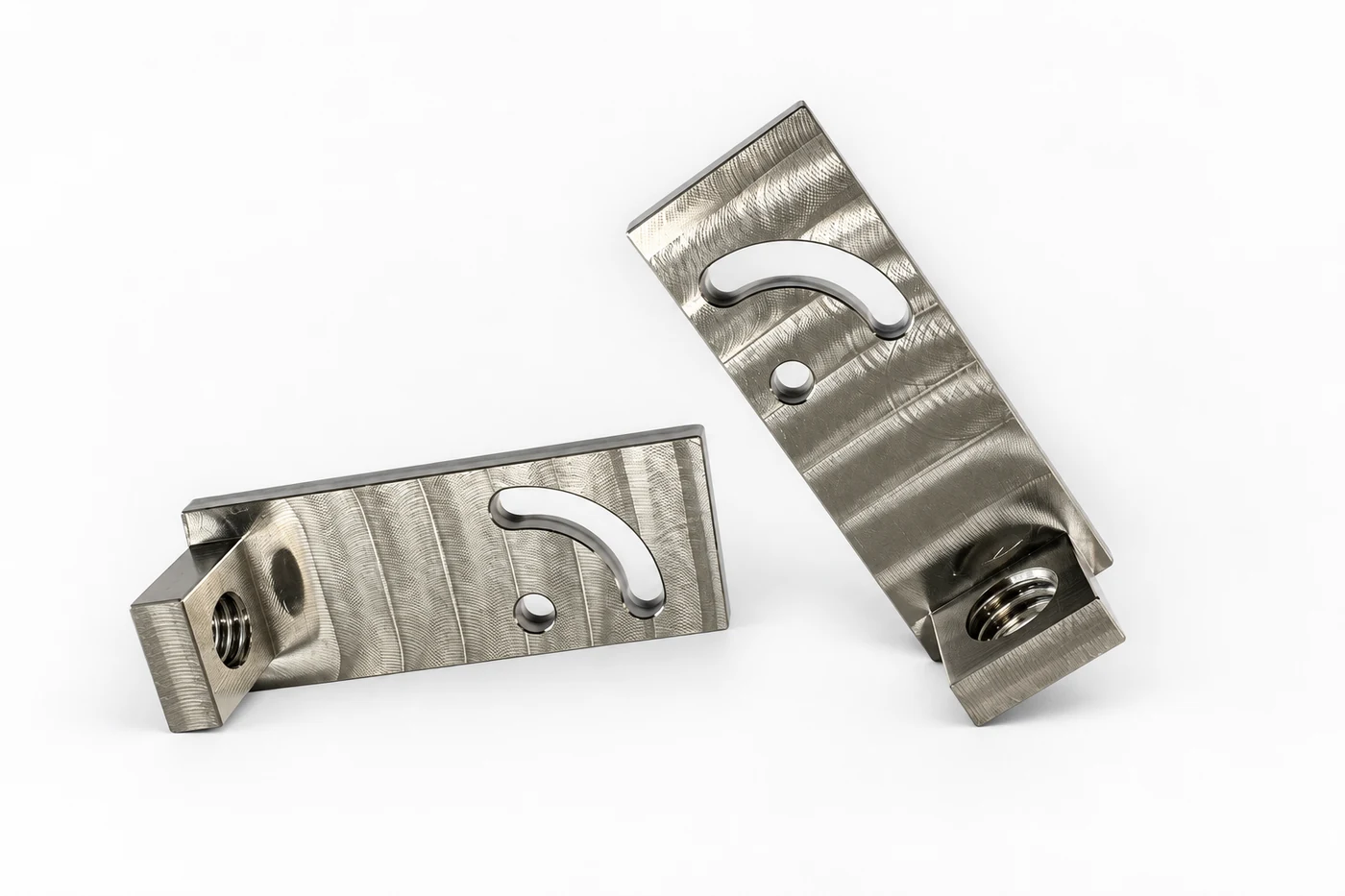
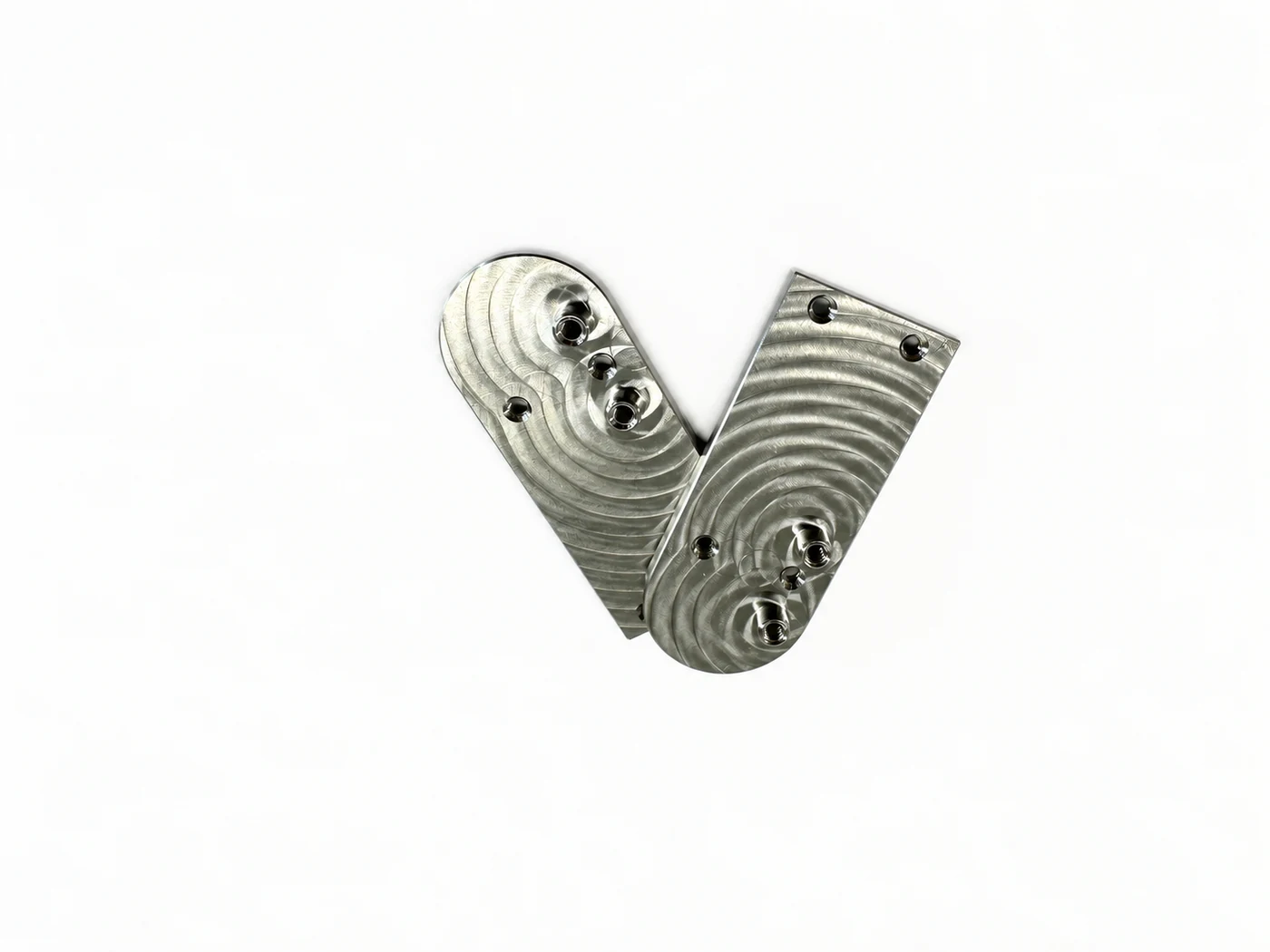
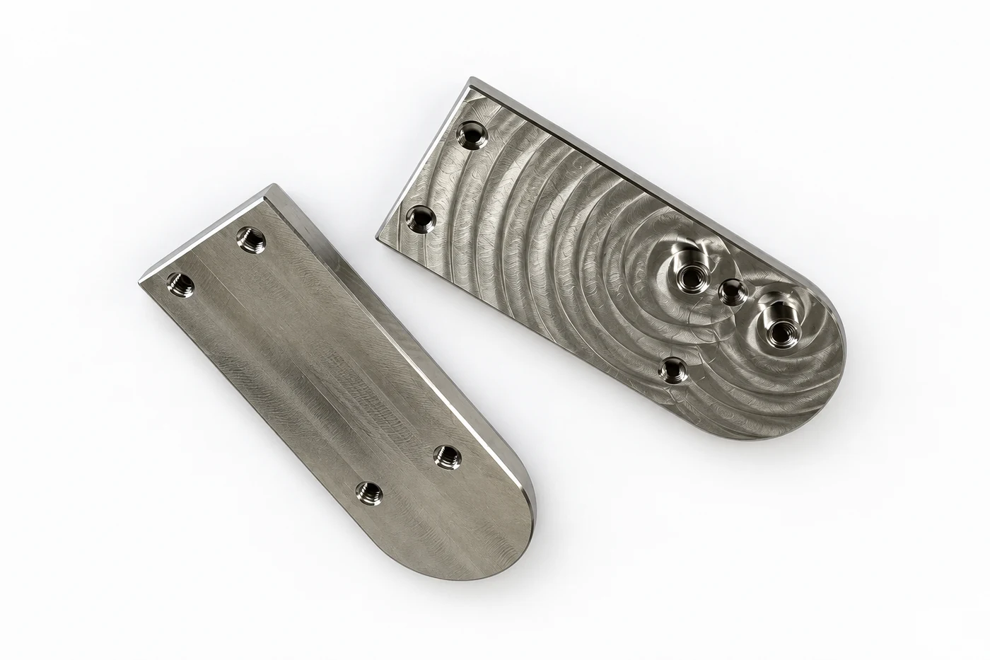
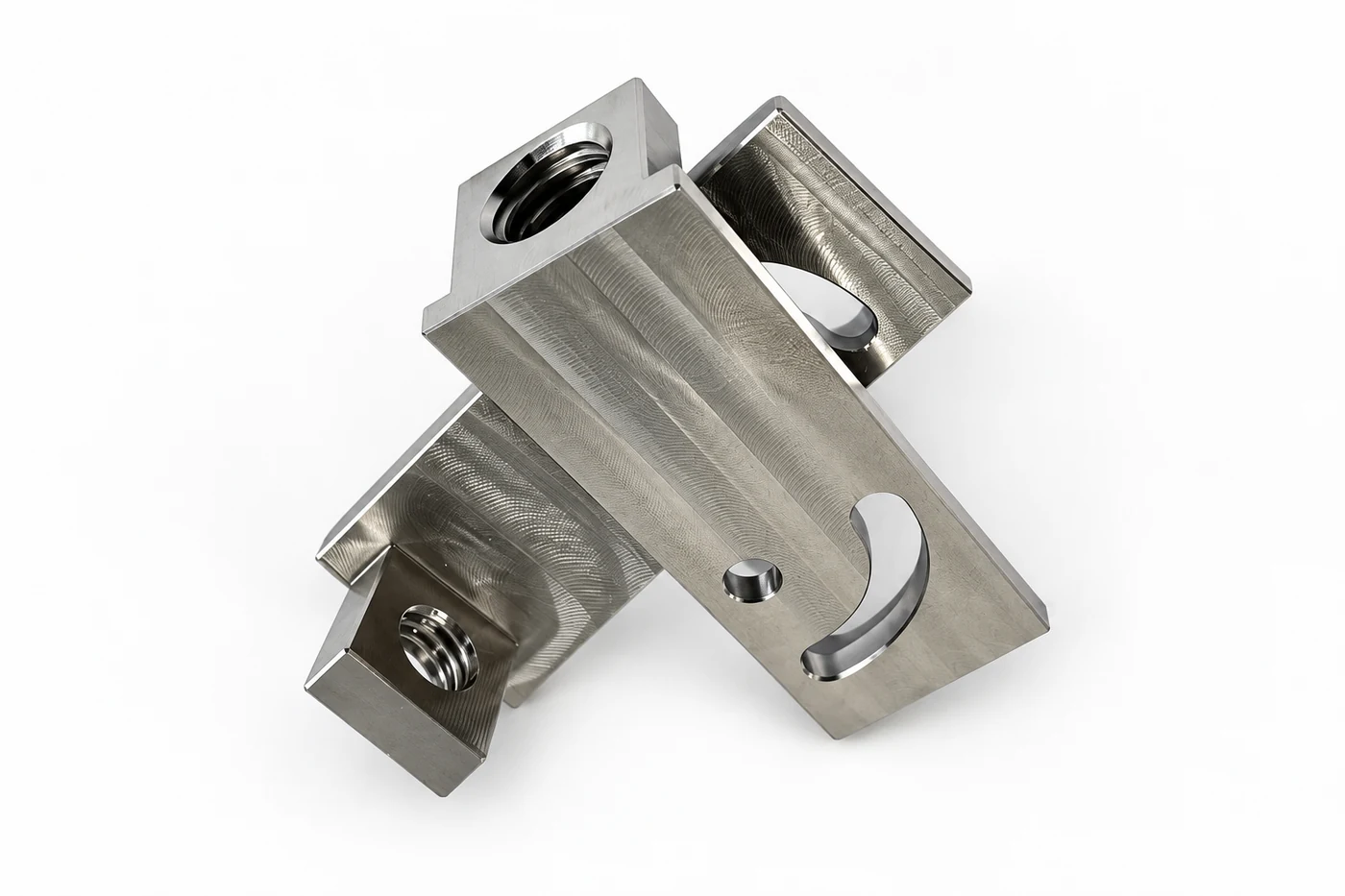
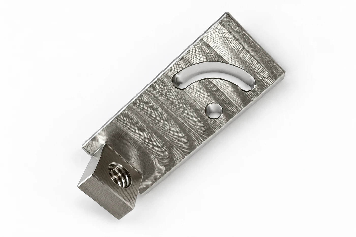
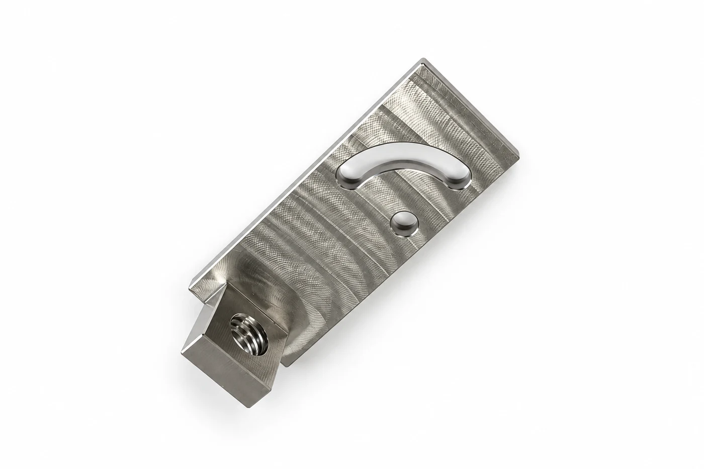
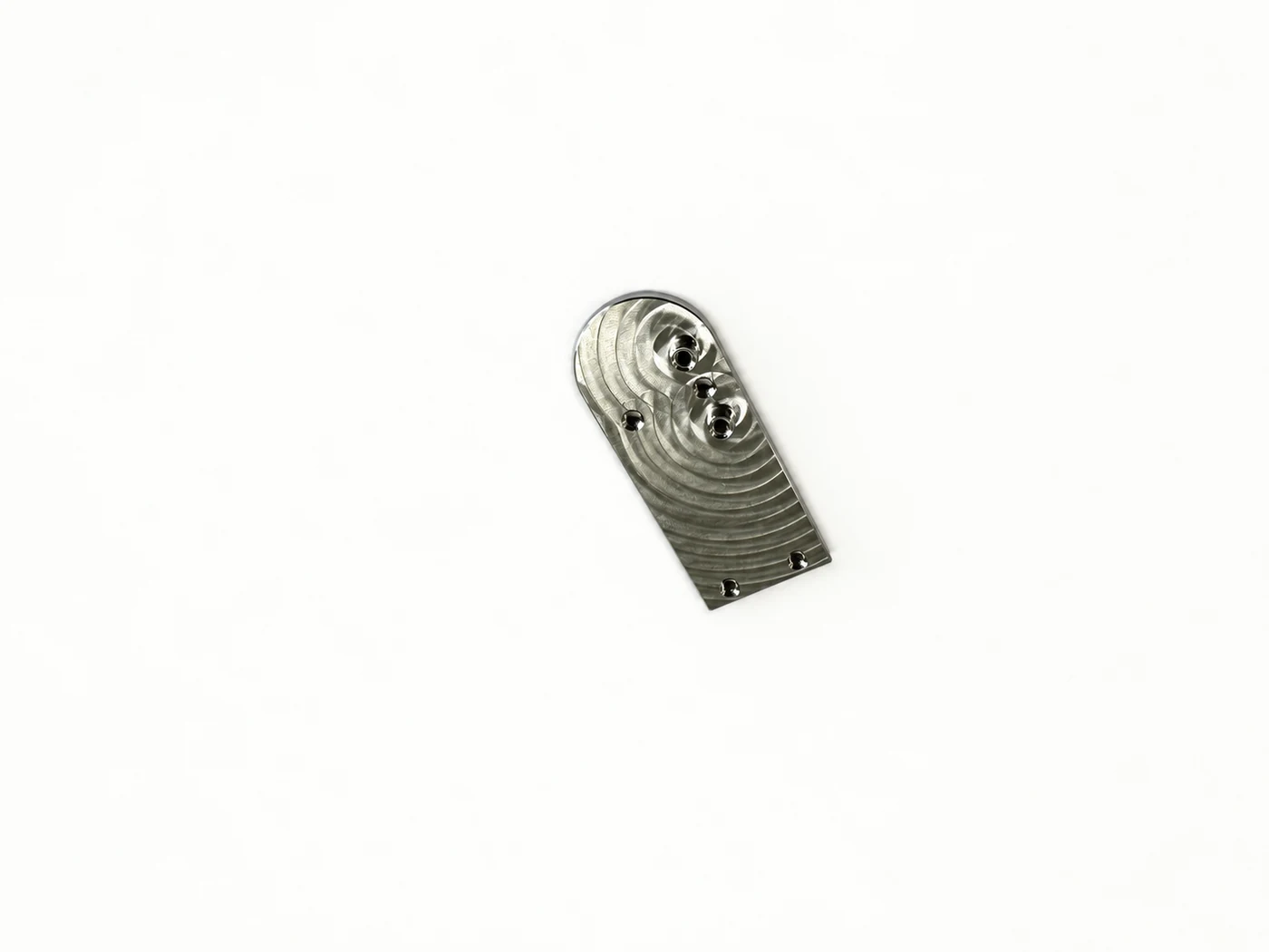
MCT는 머시닝센터를 뜻하며, SUS는 스테인리스강 계열을 가리키는 재질 표기입니다. 사진은 광학기계에 사용하기 위해 MCT로 제작한 SUS 부품입니다. 둥근 끝단의 플레이트와 원호형 장공·측면 나사가 있는 브래킷 형상을 확인할 수 있습니다. 1~2개 제작의 핵심은 필요한 기능을 도면으로 구체화하고, 기준을 유지하며 가공한 뒤 각 부품의 중요한 특성을 직접 확인하는 것입니다.
기능에서 도면으로
설치면·홀·슬롯의 관계와 광학 조립 요구를 기능별로 구분합니다.
공정에서 기준 유지
SUS 절삭과 다면 고정을 연결하고 가공·고정 변형을 관리합니다.
한두 개도 개별 검증
부품별 측정 결과와 체결·사용 조건을 연결해 납품 기준을 맞춥니다.
01광학 기능과 도면 기준
광학기계 부품과 기능 요구
광학기계용 플레이트와 브래킷은 렌즈나 센서를 직접 담지 않더라도, 연결된 조립체의 위치와 자세를 지지할 수 있습니다. 외형 치수가 맞는 것과 체결 후 광학계의 정렬이 유지되는 것은 서로 다른 확인 항목입니다. 제작 목표는 부품의 기준면에서 조립 기준, 광축 또는 센서 기준까지 이어지는 관계를 명확하게 만드는 데 있습니다.
제공된 사진은 광학기계에 사용하는 SUS 부품의 1~2개 소량 제작 사례입니다. 둥근 끝단과 여러 홀이 있는 플레이트, 원호형 관통 장공·원형 홀·측면 암나사를 가진 브래킷이 보입니다. 구체적인 SUS 강종과 각 홀의 역할은 도면으로 확인해야 하며, 원호형 장공만 보고 각도 조절 기구라고 단정할 수는 없습니다.
형상에서 검사 항목으로
| 사진 속 요소 | 확인할 기능 관계 | 도면·검사 연결 |
|---|---|---|
| 넓은 평면 | 실제 접촉면인지, 단순 외관면인지 | 접촉 영역의 평면도와 지지 상태 |
| 여러 원형 홀 | 체결용인지, 위치 결정용인지 | 홀 크기·위치와 기준면 관계 |
| 원호형 장공 | 통과·간섭 회피·이동 허용 중 요구 기능 | 폭, 원호 중심, 끝단과 주변 홀의 관계 |
| 측면 암나사와 단차 | 상대 부품의 체결 방향과 접촉 위치 | 나사 규격·유효 깊이·축 방향·단차 높이 |
위치 결정과 체결을 구분하면 필요한 공차가 선명해집니다. 볼트의 틈새로 위치가 달라지는 구조라면 홀 지름만 엄격하게 관리해도 조립 반복성이 확보되지 않습니다. 핀·어깨·접촉면이 위치를 정하는지, 조정 후 체결로 유지하는지를 먼저 결정하고, 그 기능에 맞춰 홀과 면의 공차를 배분해야 합니다.
치수 합격과 정렬 유지
미국 애리조나대학교의 광학 마운트 연구는 이 차이를 잘 보여줍니다. 연구진은 스테인리스 미러 마운트의 잠금 전후 열적 기울기 변화를 비교했습니다. 초기 실온 변화 시험에는 광학 테이블의 변형도 섞여 있었으므로, 마운트를 직접 가열하고 그 온도를 측정하는 시험으로 영향 요인을 구분했습니다. 이는 특정 잠금 구조의 실험이며, 사진 속 부품의 성능을 뜻하지 않습니다.
따라서 광학 정렬에 관여하는 맞춤 부품은 단품 측정과 조립 검증의 역할을 나눠야 합니다. 단품에서는 기준면·홀·나사를 확인하고, 조립체에서는 지정한 체결 순서와 사용 온도 조건에서 위치·기울기·복귀성을 확인합니다. 1~2개 제작에서도 이 기준을 먼저 정해야 완성품을 다시 깎는 시행착오를 줄일 수 있습니다.
도면·기준면·공차 설계
3D 모델은 형상을 전달하지만, 어느 면을 기준으로 합격 여부를 판단할지는 별도로 정해야 합니다. 도면에는 재질과 공급 상태, 주요 치수, 기능 공차, 나사, 모서리와 표면 요구를 연결해 표시합니다. 광학기계 부품에서는 실제 조립 접촉면과 정렬에 영향을 주는 형상을 우선해야 합니다.
기능 기준과 가공 기준
데이텀 형체는 실제 부품의 면이나 홀처럼 기준을 설정하는 데 쓰는 형상입니다. 데이텀은 그 형체로부터 규정된 방식으로 설정하는 이상적인 평면·축 등의 기준입니다. 가장 넓은 면을 무조건 1차 기준으로 정하기보다, 부품이 조립체에 실제로 안착하는 면과 위치 결정 구조를 따라 기준 순서를 정해야 합니다.
예를 들어 평면에 안착하고 옆면과 끝면으로 위치를 정하는 조립이라면, 그 접촉 관계를 A·B·C 기준 체계로 표현할 수 있습니다. 반대로 두 핀으로 위치가 정해지는 구조라면 홀을 포함한 기준 체계가 더 적합할 수 있습니다. 가공 지그가 편하다는 이유만으로 기능 기준을 바꾸면, 검사 합격과 조립 적합성 사이에 차이가 생깁니다.
| 관리 항목 | 설명하는 내용 | 혼동하기 쉬운 점 |
|---|---|---|
| 크기 공차 | 홀 지름, 두께, 장공 폭 등의 허용 크기 | 크기가 맞아도 위치·방향은 틀릴 수 있습니다. |
| 평면도 | 해당 면 자체의 평탄한 정도 | 다른 면과 평행하다는 뜻은 아닙니다. |
| 평행도·직각도 | 지정 기준에 대한 방향 관계 | 기준과 평가 영역이 필요합니다. |
| 위치도·윤곽도 | 규정된 위치 또는 윤곽의 허용 영역 | 도면 체계·기준·수식기호에 따라 평가가 달라집니다. |
기능을 지키는 DFM
원호형 장공은 폭만 지정해서는 주변 홀과의 관계가 전달되지 않습니다. 원호 중심·반지름·끝단 형상과 기준 체계가 필요하며, 원형 홀이 회전 중심으로 설계되었다면 그 축과 원호 중심의 일치를 특히 확인하며, 그 밖의 위치 관계도 조립 기능에 따라 관리합니다. 모든 형상을 동시에 가장 잘 맞추는 검사 정렬은 기능 기준에서 생긴 오차를 감출 수 있으므로, 도면의 기준 순서를 유지해야 합니다.
DFM은 필요한 정밀도를 낮추는 작업이 아니라, 기능과 무관한 가공 부담을 줄이는 검토입니다. 좁고 깊은 내부 모서리는 작은 공구와 긴 돌출 길이를 요구합니다. 상대 부품과 간섭하지 않는 범위에서 내부 반지름을 키우고, 공구와 측정자가 접근할 공간을 확보하면 가공과 검사가 함께 쉬워집니다. 외관면까지 기능면과 같은 공차로 묶지 않는 것도 1~2개 제작의 비용을 줄이는 방법입니다.
ISO GPS와 ASME GD&T는 기본 해석 규칙과 일부 표기 의미가 다릅니다. 적용 규격과 판본을 도면에 명확히 하고, 일반공차만으로 부족한 기능 형상에 개별 공차를 부여해야 합니다. 공차 수치는 광학 정렬 예산과 상대 부품의 변동을 검토한 뒤 정하며, 사진만으로 임의의 마이크로미터급 사양을 만들지 않습니다.
02SUS 소재와 고정 설계
SUS 소재와 변형 관리
SUS라는 명칭만으로 절삭성과 열변형 특성이 정해지지는 않습니다. 강종, 열처리·냉간가공 상태, 판재·봉재 구분과 소재 이력까지 확인해야 합니다. 같은 명목 치수의 소재라도 초기 휨과 내부 잔류응력이 다르면, 한쪽 면을 많이 제거한 뒤 나타나는 변형이 달라질 수 있습니다.
세 가지 변형의 구분
| 원인 | 발생 과정 | 구분할 관찰 |
|---|---|---|
| 잔류응력 재분포 | 소재 제거로 내부 힘의 균형 변화 | 온도 안정·고정 해제 후 남는 휨과 비틀림 |
| 고정·절삭 하중 | 누르는 힘과 절삭력에 의한 탄성변형 | 고정력·지지 위치를 바꿀 때의 변위 |
| 온도 변화 | 균일 팽창 또는 온도 구배에 따른 휨 | 부품 온도와 시간에 따른 치수 변화 |
2020년의 Al7050-T7451 판재 연구에서는 층별 절삭 후 고정을 풀고 격자점의 높이를 측정했습니다. 초기 휨과 고정 시 펴지는 효과, 절삭 유래 표면 응력을 함께 고려해 잔류응력을 역산했습니다. 이 결과는 알루미늄 시험편에 관한 것이므로 SUS의 변형량에 대입할 수 없습니다. 실무에 가져올 부분은 가공 중 고정된 형상과 해제 후 형상을 나눠 측정하는 접근입니다.
얇은 플레이트는 양면 제거량과 황삭 순서를 검토하고, 두꺼운 단차가 남는 브래킷은 비대칭 강성과 제거량을 함께 봅니다. 황삭 후 온도를 안정시키고 재안착해 기준면과 남은 여유를 측정하면 정삭 계획을 수정할 수 있습니다. 정해진 시간 동안 방치하면 잔류응력이 모두 없어진다는 가정은 피해야 합니다. 열처리 역시 강종·내식성·조직에 영향을 주므로, 강종이 확인되지 않은 부품에 일괄 적용할 수 없습니다.
열팽창과 광학 정렬
참고 물성으로 Outokumpu의 304/4301 자료는 20~100°C 구간의 평균 선팽창계수를 16.0×10⁻⁶/K로 제시합니다. 이를 일정하다고 놓은 단순 계산에서 길이 100mm가 균일하게 5°C 상승하면 길이 변화는 약 0.008mm, 즉 8µm입니다. 이는 실제 부품의 강종·길이·온도를 나타내는 값이 아니며, 구속과 온도 구배가 없는 자유 팽창의 예입니다.
광학계에서 중요한 것은 그 길이 변화가 어느 방향의 상대 이동으로 나타나는가입니다. 지지점 간 온도 차, 상대 부품과의 열팽창 차, 체결 구속이 있으면 단순한 길이 변화가 기울기나 접촉 하중 변화로 이어질 수 있습니다. 따라서 SUS라는 이유만으로 열적 정렬 안정성을 보증하기보다, 실제 강종과 조립 경로를 기준으로 검토해야 합니다.
위치 결정·지지·클램핑
위치 결정은 부품의 좌표를 정하고, 지지는 하중을 받아 변형을 줄이며, 클램핑은 부품이 그 위치에서 떨어지거나 미끄러지지 않게 유지합니다. 세 역할을 구분하지 않고 바이스를 강하게 조이면, 가공 중에는 평평해 보이지만 풀었을 때 휘는 부품을 만들 수 있습니다.
접촉점과 하중 경로
평면형 부품의 3-2-1 위치 결정은 세 점으로 1차 지지 평면을 만들고, 두 점과 한 점으로 나머지 위치·회전을 제한하는 출발점입니다. 이는 이상적인 강체의 위치 결정 원리입니다. 얇은 판의 변형까지 없애 주지는 않으므로, 보조 지지는 기준 위치를 억지로 바꾸지 않게 접촉시키고 고정해야 합니다.
| 형상·상태 | 주요 위험 | 고정 검토 |
|---|---|---|
| 넓고 얇은 플레이트 | 지지점 사이를 누르며 휨 | 누름점 아래 지지, 접촉면 청결과 안착 확인 |
| 원호형 장공 주변 | 남은 좁은 연결부의 변형·진동 | 가능하면 강성이 높은 영역으로 힘 전달 |
| 두꺼운 끝단과 단차 | 높이 차로 인한 들림과 편심 하중 | 단차를 반영한 소프트 조 또는 지지 검토 |
| 이미 정삭한 기준면 | 칩 눌림, 압흔, 재고정 위치 변화 | 접촉 부위 보호와 재안착 변동 확인 |
클램프의 힘은 가능한 한 지지점이나 충분히 강한 부분으로 전달합니다. 절삭력이 방향을 바꾸는 원호 가공과 관통 직전의 홀 가공에서는 들림과 회전도 검토해야 합니다. 일정한 체결 토크는 재현성을 돕지만 마찰·나사 상태에 따라 실제 고정력이 달라지므로, 토크 수치만으로 변형과 미끄럼을 모두 판단할 수는 없습니다.
고정력 검증과 소량 지그
Lee와 Haynes의 ASME 연구는 부품을 탄성체로 모델링하고 접촉 마찰을 포함해 고정력을 분석했습니다. 스토퍼가 있는 경우와 마찰만으로 버티는 경우의 조건이 달랐으며, 고정을 강하게 할수록 발생하는 변형도 함께 계산했습니다. 특정 부품용 토크를 제공한 연구가 아니라, 미끄럼 방지와 변형 억제를 동시에 검토해야 한다는 역학적 근거입니다.
1~2개 제작에서는 모듈 지그나 가공한 소프트 조가 합리적일 수 있지만, 제작 수량만으로 방식을 결정하지는 않습니다. 같은 부품을 풀고 다시 놓았을 때 기준면 높이와 기준 홀 위치가 얼마나 바뀌는지 확인합니다. 고정 전후 형상은 같은 온도·지지 조건에서 비교하고, 변형이 크면 힘을 더 주기 전에 지지 위치와 하중 경로를 수정해야 합니다.
03다면 공정과 절삭 원리
다면 가공과 기준 전달
플레이트의 앞뒤 면과 브래킷의 측면 나사는 서로 다른 방향에서 공구가 접근합니다. 따라서 공정 순서는 형상을 하나씩 완성하는 목록이 아니라, 어느 기준을 언제 만들고 다음 고정에서 어떻게 재현할지 정하는 계획이어야 합니다. 먼저 만든 면의 오차나 재안착 시 들림은 다음 면의 홀 위치와 나사 축 방향에 전달될 수 있습니다.
황삭에서 최종 형상까지
| 계획 단계 | 목적 | 다음 단계 전 확인 |
|---|---|---|
| 소재·초기 기준 준비 | 안정적으로 잡을 면과 가공 여유 확보 | 소재 상태, 초기 휨, 기준 접근성 |
| 외곽·단차 황삭 | 필요 형상에 접근하며 정삭 여유 유지 | 제거량의 비대칭, 남은 강성, 변형 |
| 기준 정삭·재안착 | 다음 방향 가공에 쓸 기준 확정 | 칩·버 제거, 안착, 남은 여유 분포 |
| 홀·장공·측면 가공 | 기능 형상 사이 관계 완성 | 위치·축 방향, 지지와 공구 간섭 |
| 고정 해제·마감·검사 | 납품 상태의 형상과 표면 확인 | 도면에서 지정한 최종 상태의 치수, 모서리, 잔류 칩 |
표는 검토 순서의 예이며, 사진 속 부품의 실제 작업 이력을 재현한 것은 아닙니다. 특히 관통 장공을 일찍 완성하면 주변 단면의 강성이 낮아질 수 있습니다. 반대로 나중에 가공하면 이미 완성한 면을 지그가 가리거나 버 제거 접근이 어려울 수 있으므로, 남겨 둘 연결부·지지 영역·정삭 순서를 함께 정해야 합니다.
재고정 오차와 장비 선택
서로 엄격한 위치 관계를 갖는 홀과 장공은 접근성과 지지가 허용하면 같은 고정에서 가공하는 편이 기준 전달을 줄입니다. 재고정이 필요하면 기존 기준면·기준 홀을 다시 확인하고, 새 작업 좌표계와 프로그램 원점의 관계를 검증합니다. 기상 프로빙은 안착과 원점 설정에 도움이 되지만, 같은 기계에서 공유하는 오차까지 모두 독립적으로 검증하는 수단은 아닙니다.
3축 장비의 여러 고정, 3+2축의 방향 분할 가공, 동시 5축 가공은 서로 다른 선택지입니다. 측면 접근만 필요하다면 공구 자세를 계속 바꾸는 동시 5축이 필수인 것은 아닙니다. 회전축을 이용하면 재고정 횟수를 줄일 수 있지만, 회전 중심 보정·축 정렬·공구 길이·지그 간섭을 함께 관리해야 합니다. 사진만으로 사용 장비의 축 수를 확인할 수는 없습니다.
초소량 제작에서는 공구 경로의 충돌 검토뿐 아니라 공정 중 확인 지점을 미리 정하는 것이 효과적입니다. 되돌리기 어려운 장공·나사·최종 두께를 완성하기 전에 기준 위치와 여유를 확인하고, 동일한 두 번째 부품이 있으면 첫 부품의 수정 내용을 반영합니다. 형상이나 도면이 다른 두 부품은 서로의 합격 근거가 될 수 없습니다.
SUS 절삭과 안정성
SUS를 가공할 때는 회전수와 이송속도만 정해서는 부족합니다. 실제 강종과 공급 상태를 확인하고, 공구가 한 번에 물고 들어가는 폭과 깊이, 칩 배출 공간, 부품을 지지하는 방향을 함께 검토해야 합니다. 오스테나이트계라면 가공경화와 응착, 절삭부의 열 집중이 특히 중요한 검토 대상입니다.
날당이송과 실제 칩 두께
기본 관계는 vf = n × zc × fz입니다. vf는 분당 이송거리, n은 회전수, zc는 계산에 사용하는 유효 날 수, fz는 날당이송입니다. 절삭속도는 vc = πDn/1000으로 연결되며, D를 mm로 넣으면 vc는 m/min이 됩니다.
그러나 날당이송이 곧 모든 순간의 칩 두께는 아닙니다. 절삭폭과 진입각, 원호 경로에 따라 칩 두께가 달라집니다. 절삭폭을 줄인 뒤 이송도 무조건 낮추면, 날끝이 재료를 충분히 전단하지 못하고 문지르는 구간이 늘어날 수 있습니다. SUS에서는 이 마찰과 눌림이 다음 절삭의 부담을 키울 수 있으므로 공구 권장 범위 안에서 조합을 조정해야 합니다.
| 조정 항목 | 함께 살펴볼 영향 | 확인할 결과 |
|---|---|---|
| 절삭폭·절삭깊이 | 물림각, 칩 단면, 힘의 방향 | 벽면 휨, 치수 변화, 절삭음 |
| 날당이송·회전수 | 칩 두께, 열, 공구 마모와 진동 | 칩 배출, 날끝 상태, 가공면 |
| 공구 돌출·홀더 | 공구계의 강성과 런아웃 | 상·하부 치수 차이와 반복 무늬 |
| 냉각·윤활 공급 | 접촉부 윤활, 칩 재절삭, 열 반복 | 응착·깨짐·잔류 칩 발생 |
처짐과 재생 채터
정적 처짐은 절삭력에 밀려 공구나 부품이 탄성 변형되는 현상입니다. 단순 외팔보에서는 처짐이 길이의 세제곱에 비례하므로 돌출 길이를 줄이는 효과가 큽니다. 다만 실제 엔드밀의 날홈과 홀더 접촉부는 단순 원형 봉과 달라, 이 관계만으로 완성 치수 오차를 예측할 수는 없습니다.
재생 채터는 앞선 날이 남긴 물결과 다음 날의 절삭이 상호작용해 진동이 커지는 현상입니다. 회전수를 낮추는 조치가 항상 해법은 아닙니다. 물림 조건과 공구계의 동특성에 맞는 안정 영역을 찾아야 합니다. 냉각 역시 공급량만의 문제가 아닙니다. 스테인리스 면밀링 연구에서는 윤활 방식에 따라 절삭량과 날끝 손상의 양상이 달랐습니다. 연구의 최적 조건을 강종과 공구가 다른 소형 부품에 그대로 적용해서는 안 됩니다.
04평면과 외곽 가공
평면 가공과 표면 품질
사진의 넓은 평면에 보이는 원호 모양 절삭 무늬는 회전하는 날과 이송 운동이 만든 흔적입니다. 조명 방향에 따라 무늬의 밝기와 대비가 크게 바뀌므로, 사진의 광택만으로 거칠기 수치나 평면도를 판정할 수 없습니다. 광학기계에 들어가는 금속 구조부품이라고 해서 모든 면이 광학 연마면이어야 하는 것도 아닙니다.
외관·거칠기·형상 평가
| 항목 | 평가하는 대상 | 단독으로 알 수 없는 것 |
|---|---|---|
| 외관·절삭 무늬 | 육안상 균일성, 흠집, 눌림과 변색 | 정량 거칠기와 면 전체의 평면도 |
| 표면거칠기 | 정해진 측정 조건에서의 미세 요철 | 부품 전체의 휨과 기준면에 대한 자세 |
| 평면도 | 해당 면 자체의 형상 편차 | 다른 기준면에 대한 평행도·직각도 |
| 평행도·직각도 | 지정 기준에 대한 면·축의 방향 관계 | 표면의 미세 흠집과 국부 오염 |
면밀링의 표면 형성에는 날끝 형상과 이송뿐 아니라 날마다 다른 축방향 높이, 즉 런아웃이 관여합니다. 가장 낮게 돌출된 날이 표면을 주로 형성하면, 같은 프로그램 이송에서도 예상과 다른 반복 무늬가 남습니다. 탄소강과 원형 인서트를 사용한 실험에서도 날 높이 차이가 측정 거칠기에 영향을 주었습니다. 이는 장착 상태를 확인할 근거이며, 해당 실험 수치가 이 SUS 부품의 거칠기를 예측한다는 뜻은 아닙니다.
기능면과 검사 조건
조립 접촉면은 접촉 범위와 들뜸, 볼트 체결 후 자세 변화까지 고려합니다. 광로에 노출되는 면은 파장과 입사·관찰 각도에 따른 산란·반사 요구를 별도로 확인합니다. 필요하면 BRDF처럼 각도에 따른 반사를 평가하는 지표를 검토합니다. 검게 보인다는 이유만으로 성능을 판정하거나, 모든 SUS 면에 흑화를 요구하지는 않습니다. 접착면이라면 거칠기뿐 아니라 잔류 가공유와 후처리의 접착 적합성이 함께 문제됩니다. 한 가지 외관 기준으로 이 면들을 모두 관리하면 비용은 늘고 필요한 성능은 놓칠 수 있습니다.
거칠기를 비교할 때는 측정 방향, 위치, 필터와 평가 길이를 통일합니다. 평면도는 세척한 부품을 합의한 지지 조건에서 평가하고, 평행도는 지정 기준을 설정한 뒤 따로 확인합니다. 가공 직후 고정된 상태에서 평평해 보이는 면도 풀고 온도가 안정된 뒤에는 달라질 수 있으므로, 최종 사용·검사 조건에 맞춘 판정이 필요합니다.
외곽·단차와 공구 접근
플레이트의 둥근 끝단과 브래킷의 높은 단차는 모두 윤곽 가공이지만 공구가 받는 조건은 다릅니다. 바깥쪽 볼록 원호는 공구가 외곽을 따라 이동할 공간이 비교적 넓습니다. 반면 단차 안쪽과 오목한 연결부에서는 공구 직경, 목 길이, 홀더 간섭이 동시에 제한됩니다.
도면 반경과 공구 반경
회전 공구로 안쪽 수직 모서리를 가공하면 공구 반경에 따른 곡면이 남습니다. 설계에서 날카로운 안쪽 모서리를 요구한다면 상대 부품의 모따기나 릴리프, 별도 가공법을 검토해야 합니다. 공구가 들어갈 수 있다는 이유만으로 허용된 연결 반경이나 접촉 범위를 바꿔서는 안 됩니다.
오목한 코너의 반경에 공구 반경을 지나치게 가깝게 맞추면, 코너 진입 시 물림각이 급격하게 커질 수 있습니다. 이때 절삭력과 진동이 증가하면서 코너가 더 깎이거나 날끝이 손상될 수 있습니다. 작은 공구로 잔삭을 분리하거나 경로를 완만하게 설계하는 이유가 여기에 있습니다. 최종 반경은 도면을 유지하고, 황삭용 경로와 정삭용 경로를 구분합니다.
벽면 깊이와 형상 오차
긴 날로 단차 벽을 한 번에 가공하면 공구 처짐 때문에 위와 아래의 치수가 달라질 수 있습니다. 여러 깊이로 나누면 부하를 줄일 수 있지만 경계에 미세한 단이 남을 수 있습니다. 따라서 깊은 벽은 충분한 날 길이와 목 여유, 돌출 강성을 확인하고, 정삭에서 제거할 잔여량을 일정하게 만드는 것이 중요합니다.
공구 지름 보정은 평균적인 크기 오차를 조정하는 수단입니다. 벽면의 테이퍼나 물결, 고정 변형까지 하나의 보정값으로 해결할 수는 없습니다. 외곽 치수와 함께 높이별 벽 위치, 단차 높이, 바닥과 벽의 방향 관계를 확인해야 원인을 구분할 수 있습니다.
소량 제작의 경로 검증
한두 개 제작에서는 복잡한 전용 공구보다 보유 공구와 안정적인 재고정으로 해결하는 편이 합리적일 수 있습니다. 다만 CAM의 명목 공구 형상만 확인해서는 부족합니다. 실제 홀더와 바이스, 잔여 소재를 포함해 진입·퇴피 경로를 검토하고, 가공 후 남겨야 할 지지 영역이 너무 일찍 없어지지 않는지 확인합니다. 최종 윤곽을 끝내는 시점은 부품을 안전하고 정확하게 지지할 방법과 함께 결정합니다.
05원호형 장공과 체결 홀
원호형 장공 가공
사진 속 브래킷에는 곡선을 따라 이어지는 관통 장공이 보입니다. 이런 형상은 각도 조정이나 이동 여유를 제공하는 설계에 쓰일 수 있지만, 실제 역할은 조립도와 상대 부품으로 확인해야 합니다. 가공 관점에서는 슬롯 폭뿐 아니라 원호 중심, 내·외측 반경, 양 끝 형상과 인접 홀의 관계가 하나의 형상 묶음입니다.
슬롯 폭과 전체 윤곽
| 검사 항목 | 확인할 내용 | 주의할 판정 |
|---|---|---|
| 슬롯 폭 | 여러 원호 위치와 필요 시 깊이별 폭 | 한 지점의 측정값으로 전체 폭을 대표하지 않음 |
| 원호 중심·반경 | 도면 기준에 대한 내·외측 윤곽 | 폭이 일정해도 중심 위치가 어긋날 수 있음 |
| 양 끝과 전이부 | 끝단 반경, 연결 상태, 진입·퇴피 흔적 | 중앙 구간만 측정하면 국부 과삭을 놓침 |
| 주변 형상과의 관계 | 홀 축, 단차, 외곽과의 위치 관계 | 개별 형상이 합격해도 조립 관계는 별도 확인 |
슬롯과 같은 폭의 공구로 한 번에 완성하면 양쪽 벽이 서로 다른 절삭 조건을 겪고, 공구 처짐과 런아웃이 완성 폭에 직접 반영됩니다. 폭보다 작은 공구로 황삭 후 양쪽 벽을 정삭하는 방식은 보정 여유를 확보합니다. 다만 좁은 슬롯에서는 작은 공구의 강성과 칩 배출이 다시 제한되므로, 무조건 작은 공구가 유리한 것은 아닙니다.
원호 경로의 이송 기준
오목한 원호 벽을 가공할 때 공구 중심은 완성 윤곽보다 작은 원을 돕니다. 부품 반경 R, 공구 반경 r인 단순 내측 원호라면 같은 각속도에서 공구 중심 이송 = 윤곽 이송 × (R−r)/R입니다. 예를 들어 R=10 mm, r=3 mm라면 비율은 0.7입니다. 이는 기하 관계를 설명하는 예이며 이 부품의 치수나 권장 절삭조건이 아닙니다.
반대쪽 볼록 원호에는 같은 보정식을 그대로 적용할 수 없습니다. CAM과 제어기가 어떤 경로를 기준으로 이송을 해석하는지 확인해야 이중 보정을 피할 수 있습니다. 관통 직전에는 바닥 지지와 남은 칩의 배출을 확인하고, 가공 후에는 입구뿐 아니라 출구 모서리와 깊이 방향 벽 상태까지 살펴봅니다.
홀·자리파기·측면 나사
플레이트와 브래킷의 홀은 지름만 맞추면 끝나는 형상이 아닙니다. 실제 용도가 볼트 통과인지 위치결정인지에 따라 필요한 공차와 검사 방법이 달라집니다. 사진의 확대된 홀 입구도 자리파기인지 모따기인지, 어느 깊이까지 이어지는지는 도면과 실측으로 구분해야 합니다.
홀 요구와 가공법
드릴은 소재 제거에 효율적이지만, 시작 면의 기울기와 런아웃, 칩 배출에 따라 홀의 위치와 형상이 영향을 받습니다. 리밍은 크기와 표면 개선에 유용하나 기존 홀의 큰 위치 오차를 수정하는 공정으로 간주하면 안 됩니다. 위치나 진원도 요구가 높으면 보링 또는 원호 보간 가공의 적용 가능성을 함께 검토합니다. 어떤 공정을 선택하든 결과는 실제 검사로 확인합니다.
| 형상 | 도면에서 확정할 사항 | 빠뜨리기 쉬운 확인 |
|---|---|---|
| 원형 홀 | 지름, 깊이·관통 여부, 기준과 위치 | 축 기울기, 출구 버, 깊이별 크기 |
| 자리파기·좌면 | 지름, 깊이, 바닥 형상과 좌면 방향 | 잔여 바닥 두께와 상대 머리의 안착 |
| 내부 나사 | 호칭, 피치, 공차 등급, 유효 나사 깊이 | 불완전 나사부, 바닥 여유, 잔류 칩 |
| 측면 홀·나사 | 상면·외곽·다른 홀에 대한 관계 | 재고정 기준의 전달과 공구 접근 공간 |
탭 깊이와 칩 배출
탭 가공에서는 강종에 맞는 공구와 윤활, 권장 밑구멍(탭 드릴) 지름을 함께 선택합니다. 관통홀과 막힌 홀은 칩이 나갈 방향이 다르므로 탭 형상을 구분해야 합니다. 드릴 끝의 원뿔부, 탭의 선단부, 완전한 나사산이 형성되지 않는 구간을 고려하면 드릴 깊이와 유효 나사 깊이는 같지 않습니다. 바닥에 닿은 볼트가 부품을 제대로 눌렀다고 오판하지 않도록 조립 길이도 확인합니다.
한두 개 제작에서는 탭 파손 시 이미 투입한 가공 시간이 손실될 수 있습니다. 공구 직경과 접근 공간, 제어기의 보간 기능이 허용하면 나사밀링도 비교할 수 있습니다. 최종 검사는 규격에 맞는 나사 게이지와 필요한 깊이 확인을 조합합니다. 볼트가 들어간다는 사실만으로 나사 등급이나 다른 기준에 대한 위치가 입증되지는 않습니다.
06모서리·표면과 열적 안정
모서리 마감과 세척
SUS 부품의 디버링은 손에 걸리는 부분을 없애는 작업보다 범위가 넓습니다. 홀 출구와 슬롯 하단의 작은 버도 상대 부품의 안착을 방해하거나, 체결 중 떨어져 이동할 수 있습니다. 특히 광학기계에서는 금속 입자가 이동할 수 있는 경로와 실제 광학면의 위치를 확인해야 합니다. 이 사진만으로 특정 청정도 등급이나 클린룸 요구가 있다고 단정할 수는 없습니다.
버 제거와 모따기
‘버 제거’만 적으면 작업자마다 모서리를 깎아내는 양이 달라질 수 있습니다. 명확한 모따기나 라운드가 필요한 곳은 형상과 크기를 지정하고, 형상이 정해지지 않은 모서리는 허용 상태를 합의합니다. ISO 13715는 이런 불특정 형상 모서리의 표시와 치수 기입을 다룹니다. 지정된 모따기와 불특정 모서리를 같은 지시로 취급하지 않는 것이 핵심입니다.
| 위치 | 마감 시 주의점 | 후속 확인 |
|---|---|---|
| 조립 접촉면 외곽 | 유효 접촉 폭을 과도하게 줄이지 않음 | 들뜸, 눌림, 국부 과연마 |
| 원호 슬롯의 위·아래 | 폭과 끝단 윤곽을 보존하며 버 제거 | 양쪽 모서리, 잔류 얇은 버와 칩 |
| 나사 입구 | 첫 유효 나사산과 입구 형상을 보존 | 게이지 진입, 나사 깊이, 연마 잔류물 |
| 단차 안쪽·막힌 홀 | 공구 접근과 세척액 배출을 확보 | 보이지 않는 잔류물, 건조 상태 |
후처리와 최종 공급 상태
브러시와 연마재를 사용하면 새로운 입자가 생기고 모서리 치수가 달라질 수 있습니다. SUS에서는 철계 오염의 전이를 관리하고, 세척은 오일·칩·연마 잔류물의 성질에 맞춰 정합니다. 세척과 산세, 부동태화는 목적이 서로 다르므로 광택을 낸 작업을 곧 부동태화로 부르거나 모든 부품에 동일한 화학 처리를 적용하지 않습니다.
전해연마처럼 재료를 제거하는 후처리나 별도 코팅을 적용한다면 기능면, 나사, 슬롯 폭의 최종 상태를 도면 단계에서 정해야 합니다. 마스킹 범위와 처리 전·후 어느 상태에서 판정할지도 명확히 합니다. 광로 주변에 코팅을 쓰는 경우에는 밀착 상태와 박리 입자의 발생, 세척 공정과의 적합성도 확인합니다. 마지막에는 필요한 치수를 다시 확인하고, 잔류 세척액을 제거한 뒤 서로 부딪히지 않게 포장합니다. 한두 개의 소량 부품도 이 마지막 단계에서 기능면이 손상되면 앞선 정밀가공의 가치가 사라집니다.
온도와 치수 기준
가공 직후의 SUS 부품과 검사실에 충분히 머문 부품은 같은 온도라고 볼 수 없습니다. 긴 구간의 홀 간격이나 단차 높이를 비교할 때는 절삭 중 발생한 열, 운반 환경, 손으로 잡은 위치가 측정 결과에 섞일 수 있습니다. 먼저 부품이 변했는지와 측정 조건이 달라졌는지를 구분해야 합니다.
20 °C와 실제 부품 온도
일반적인 정밀 치수 비교에서는 20 °C를 표준 기준 온도로 삼습니다. 이는 현장이 언제나 정확히 20 °C여야 한다는 뜻과는 다릅니다. 다른 온도에서 측정한다면 해당 치수를 기준 온도로 환산할 필요가 있는지 판단하고, 온도 측정과 열팽창 보정의 불확도를 함께 검토해야 합니다.
실내 온도계가 안정된 값이라고 해서 부품 내부까지 같은 온도가 되었다고 단정할 수는 없습니다. 질량, 두께 분포, 이전 공정과의 온도 차에 따라 열평형에 도달하는 시간이 달라집니다. 따라서 모든 부품에 동일한 대기 시간을 지정하기보다, 중요한 측정값과 부품 온도가 시간에 따라 어떻게 변하는지 확인해 검사 조건을 정하는 편이 합리적입니다.
강종 확인과 보정 기록
SUS라는 표기만으로 하나의 열팽창계수를 적용해서는 안 됩니다. 세부 강종과 재료 상태를 확인하고, 필요한 경우 적용 온도 구간에 맞는 재료 데이터를 사용해야 합니다. 부품과 측정 기준기가 다른 재료라면 두 물체의 온도 영향도 구분합니다.
| 관리 대상 | 확인 방법 | 검사 기록 |
|---|---|---|
| 부품 온도 | 열 영향을 받기 쉬운 위치와 두께 차이를 고려해 확인 | 측정 위치, 시각, 안정화 상태 |
| 측정 환경 | 실내 온도와 시간 변화, 국부 열원 확인 | 온도 범위와 검사 시간 |
| 재료 정보 | 도면 강종과 재료 증빙 대조 | 강종, 재료 상태, 보정에 사용한 데이터 |
| 보정 설정 | 장비의 기준 온도·재료 설정 점검 | 보정 사용 여부와 적용 기준 |
검사와 사용 조건의 연결
광학기계가 실제로 사용하는 온도와 20 °C 기준의 출하 검사는 서로 다른 질문에 답합니다. 출하 검사는 도면 적합성을, 사용 조건 검토는 조립체의 위치 변화를 다룹니다. 이 부품이 광학계의 위치를 지지하는 구조라면 상대 부품의 재료, 접촉 위치와 온도 변화도 함께 검토해야 하며, 사진만으로 온도 안정성이나 정렬 성능이 확보되었다고 판단할 수는 없습니다.
07측정과 개별품 검증
특성별 측정과 합격 판정
검사 장비는 부품의 외형보다 확인하려는 특성에 맞춰 선택해야 합니다. 외형 폭이 공차 안에 들어와도 기준면에 대한 홀 위치나 접촉면의 자세가 맞는 것은 아닙니다. 광학기계용 SUS 부품에서는 실제 조립에 사용하는 면과 홀을 도면에서 먼저 구분해야 합니다.
데이텀과 측정 좌표계
데이텀은 위치와 자세를 판단하는 기준입니다. CMM에서는 도면에 지정된 기준과 우선순위를 반영해 좌표계를 구성해야 합니다. 바이스에 물린 면이 편하다는 이유로 검사 기준까지 바꾸거나, 전체 형상이 가장 잘 맞도록 정렬한 결과를 도면 기준의 위치도와 혼동하면 조립 관계를 잘못 평가할 수 있습니다.
측정점을 몇 개 찍었는지도 결과를 바꿉니다. 원을 계산할 수 있는 최소 점수만으로는 원 전체의 형상 오차를 충분히 볼 수 없습니다. 홀의 입구와 내부, 접촉면의 여러 영역처럼 해당 결함이 나타날 수 있는 위치를 포함하고, 프로브 접근성과 고정에 따른 변형을 함께 검토합니다.
특성과 장비의 대응
| 검사 특성 | 검토할 방법 | 함께 확인할 조건 |
|---|---|---|
| 외형 폭·두께 | 마이크로미터 등 접촉식 치수 측정 | 접촉 위치, 측정력, 버와 이물 |
| 홀 위치·면의 자세 | CMM 등 좌표 측정 | 도면 데이텀, 측정점 분포, 평가 방식 |
| 작은 윤곽·모서리 | 영상 측정 등 광학식 측정 | 조명, 초점, 반사와 모서리 검출 |
| 기능면 거칠기 | 접근 가능한 형상에 맞는 조도 측정 | 파라미터, 필터, 평가 길이와 방향 |
| 나사부 | 규격과 공차 등급에 맞는 나사 게이지 | 유효 나사 길이·깊이는 별도 확인 |
광택이 있는 SUS 표면은 영상에서 보이는 경계와 실제로 측정하려는 경계가 일치하는지 확인해야 합니다. 조도를 비교할 때도 수치 이름만 맞추지 말고 평가 조건을 맞춰야 합니다. 일반 볼트가 들어간다는 확인만으로 나사 공차 검사를 대신하지 않으며, 게이지 합격과 볼트가 바닥에 닿지 않는 유효 체결 길이 확인도 구분합니다.
불확도와 판정 규칙
측정값이 공차 한계에 가깝다면 표시된 마지막 자리만으로 합격을 결정하지 않습니다. 장비 사양이나 교정 성적서가 곧바로 해당 부품 측정의 불확도는 아니므로, 고정·온도·프로브·측정 절차의 영향을 포함해 판단해야 합니다. 발주자와 제작자는 적용할 판정 규칙을 사전에 정하고, 경계 부근의 결과는 재측정이나 더 적합한 방법으로 확인하도록 합의하는 것이 좋습니다.
한두 개 제작의 품질 확인
한두 개를 만드는 주문에서는 첫 번째 완성품이 납품할 유일한 부품일 수 있습니다. 불량을 여러 개 만들어 본 뒤 조건을 조정하는 방식은 부담이 큽니다. 되돌리기 어려운 공정 전에 기준면, 중요한 홀 위치와 남은 가공 여유를 확인하고, 최종 상태에서 다시 판정하는 흐름이 필요합니다.
공정 확인과 최종 확인
공정 중 측정은 다음 가공을 진행할지 판단하는 자료입니다. 이후에 부품을 뒤집거나, 남은 소재를 제거하거나, 모서리를 다듬으면 상태가 달라질 수 있으므로 출하 검사와 같게 취급하지 않습니다. 최종 검사는 도면에서 요구한 상태와 조건에 맞춰 수행하며, 핵심 기능 치수는 납품하는 각 부품에서 확인하도록 범위를 정합니다.
한 개만 만드는 경우에도 도면 특성과 검사 결과를 연결한 기록이 유용합니다. 두 개라면 부품별 식별을 붙여 어떤 수치가 어느 부품의 값인지 구분합니다. ‘전수 검사’라는 말만으로 모든 형상과 성능을 확인했다고 해석되지 않도록, 검사한 개수와 특성 범위를 함께 적어야 합니다.
개별 부품의 검사 기록
| 기록 항목 | 한두 개 제작에서 남길 내용 |
|---|---|
| 식별 정보 | 부품 번호, 개별 식별, 도면 개정, 검사일 |
| 검사 특성 | 도면 항목 번호, 기준, 공차, 최종 상태 |
| 측정 결과 | 실측값 또는 게이지 판정, 사용 장비·방법 |
| 핵심 조건 | 데이텀 정렬, 고정 상태, 필요한 온도·조도 조건 |
| 추가 조치 | 재가공·재검사 이력, 미확인 항목과 별도 합의 |
초도품 검사라는 명칭을 쓸 때도 문서의 범위를 분명히 해야 합니다. 모든 도면 요구사항을 대조한 보고서인지, 지정된 핵심 특성만 확인한 기록인지 구분합니다. 별도 계약이 없다면 특정 산업의 인증이나 정해진 초도품 승인 체계를 충족했다고 표현하지 않습니다.
부품 치수가 합격해도 실장한 광학계의 안정성까지 입증되는 것은 아닙니다. 위치 유지가 요구되는 조립체라면 정해진 체결 순서와 조건에서 재조립 전후의 위치 변화, 필요한 온도 변화 후의 복귀 상태를 별도 시험 항목으로 정합니다. 시험 기준은 실제 장치의 성능 요구에서 정하고, 가공품 치수 성적서와 조립 시험 결과를 구분해 보관합니다.
반복 측정과 공정 능력의 구분
같은 부품을 여러 번 재어 값이 비슷하게 나오는 것은 그 조건에서의 측정 반복성을 살피는 자료입니다. 이것이 서로 다른 부품을 계속 생산했을 때의 산포를 보여 주지는 않습니다. 한두 개의 결과나 한 부품의 반복값만으로 Cp·Cpk, 불량률 또는 양산 수율을 제시해서는 안 됩니다.
측정 시스템 평가도 부품, 작업자, 날짜, 장비와 설정 등 어떤 변동을 포함했는지에 따라 의미가 달라집니다. 이번 주문에서는 장비의 적절성과 핵심 측정의 재현성을 확인하고, 결과의 적용 범위를 해당 부품과 검사 조건에 한정해 기록하는 것이 정확합니다.
08불량 진단과 제작 의뢰
가공·조립 증상과 진단
광학기계용 브래킷이나 지지 부품에서 조립이 매끄럽지 않다면, 곧바로 홀을 넓히거나 접촉면을 연마하기 전에 증상을 기록해야 합니다. 손을 대면 버, 접촉 흔적과 원래의 형상 정보가 사라져 원인 구분이 어려워집니다. 실제 역할이 확인되지 않은 부품은 조절 기능이 있다고 가정하지 않고, 도면과 상대 부품의 접촉 관계부터 대조합니다.
관찰과 측정의 연결
아래 항목은 원인을 확정하는 표가 아니라 다음 측정을 선택하는 진단 순서입니다. 한 가지 증상에 여러 원인이 함께 작용할 수 있으므로, 부품 단독 상태와 정해진 체결 상태를 구분하고 한 번에 한 조건씩 비교합니다.
| 증상 | 우선 확인할 값·상태 | 확인 후 검토할 조치 |
|---|---|---|
| 바닥면이 들뜨거나 흔들림 | 접촉면의 버·이물, 면 형상, 상대 받침면 | 이물 제거 후 재측정, 허용된 범위의 모서리 수정 또는 면 재가공 |
| 체결하면 기준 위치가 바뀜 | 체결 전후 변위, 접촉 위치, 체결 순서·조건 | 지지 위치와 체결 조건 검토, 필요 시 구조·공차 재협의 |
| 나사가 중간에 걸림 | 규격·공차, 유효 깊이, 칩, 손상·응착 흔적 | 원인 분리 후 나사 재검사, 체결 재료·표면·윤활 조건 검토 |
| 슬롯이나 홀의 한쪽만 간섭 | 양쪽 경계와 홀 위치, 기준 정렬, 상대 부품 치수 | 위치·크기 오류 구분 후 수정 범위 승인 |
| 깊은 벽면에 떨림 무늬 | 공구 상태·돌출 길이, 고정, 벽면 형상·거칠기 | 공구·지지·절삭 조건을 검토하고 남은 여유 안에서 수정 |
| 검사 시간마다 수치가 이동 | 부품 온도, 재고정, 측정 위치와 장비 상태 | 온도·고정·측정 절차를 맞춘 뒤 재확인 |
SUS 체결부의 구분 진단
SUS 체결부의 걸림은 나사 치수 문제, 바닥 닿음, 이물 또는 응착 마모 등으로 나눠 확인해야 합니다. 체결력을 더 주어 통과시키면 표면 손상과 금속 입자 발생이 커질 수 있습니다. 윤활을 검토할 때도 광학기계에서 허용하는 청정도와 표면 조건을 먼저 확인해야 합니다.
수정과 재검사의 범위
접촉면을 다시 가공하면 그 면에서 정의한 높이와 홀의 관계가 함께 바뀔 수 있습니다. 수정 승인에는 제거할 위치와 범위뿐 아니라 다시 검사할 연관 특성을 포함해야 합니다. 외관이 개선되었다는 이유만으로 종료하지 않고, 해당 기능면과 조립 관계가 도면 요구를 만족하는지 최종 상태에서 확인합니다.
소량 발주와 납품 자료
한두 개의 SUS 부품을 발주할 때는 수량보다 먼저 무엇을 기준으로 완성을 판단할지 정해야 합니다. 사진은 외형과 가공 접근을 설명하는 데 유용하지만, 홀의 공차·나사 깊이·기준면·거칠기를 모두 전달하지는 못합니다. 광학기계용이라는 용도에 더해 실제로 맞닿는 면과 상대 부품 정보를 제공해야 필요한 정밀도를 구체화할 수 있습니다.
도면과 개정 관리
2D 도면과 3D 모델을 함께 제공한다면 개정 번호를 맞추고, 서로 다를 때 어느 문서가 우선하는지 정합니다. 세부 SUS 강종, 재료 상태와 필요한 증빙도 명시해야 합니다. 제작 중 설계가 바뀌면 구두 전달에 그치지 말고 변경 특성, 적용 부품과 재검사 범위를 남겨야 합니다.
| 발주 정보 | 합의할 내용 | 견적·납품에 미치는 영향 |
|---|---|---|
| 수량·일정 | 1개 또는 2개, 희망 일정, 재주문 가능성 | 준비 작업과 재사용 가능한 자료의 범위 |
| 소재 | 세부 강종, 재료 상태, 증빙 요구 | 소재 조달과 확인 절차 |
| 기능 특성 | 기준면, 조립면, 홀 관계, 개별 공차 | 가공 순서·고정·검사 범위 |
| 표면·모서리 | 기능면 거칠기, 버·모따기, 허용 외관 | 마무리 공정과 검사 조건 |
| 검사 자료 | 핵심 특성별 실측값, 개별 식별, 필요한 보고서 | 측정 준비와 문서 작성 시간 |
| 변경 처리 | 도면 개정, 대체안 승인, 재가공 범위 | 납기와 비용 변경의 기준 |
기능에 맞춘 비용 조정
소량 제작에는 재료와 절삭 시간 외에도 도면 검토, 프로그램 작성, 고정과 검사 준비가 필요합니다. 한 개와 두 개의 가격이 단순히 배수가 되지 않는 이유를 이 준비 작업에서 찾을 수 있지만, 실제 비용은 형상과 공정 구성으로 확인해야 합니다. 납기나 단가를 사진만으로 확정해서는 안 됩니다.
비용을 조정할 때는 기능면의 요구를 먼저 유지하고, 비기능면의 과도한 공차나 불필요한 전체 연마를 검토합니다. 깊은 형상, 작은 내부 반경, 여러 방향의 가공을 변경할 수 있다면 상대 부품과의 간섭 및 조립성을 함께 확인해야 합니다. 제작 편의를 위한 형상 변경도 설계 승인 후 반영합니다.
납품 상태와 이후 활용
납품 자료는 부품 식별, 최종 도면 개정, 합의한 검사 결과와 재료 증빙이 서로 연결되도록 구성합니다. 미확인 특성이 있다면 확인한 항목과 구분하고, 포장과 취급 과정에서 기능면이 손상되지 않도록 공급 상태를 정합니다. 이 기록은 같은 형상을 다시 주문하거나 조립 문제를 검토할 때의 출발점이며, 한두 개의 납품 결과를 양산 공정 능력으로 확대 해석하지 않습니다.
English Technical Overview
Custom MCT precision-parts manufacturing connects drawing requirements with actual assembly conditions, even when only one or two parts are needed. In optical machinery, plate mounting faces, bracket height and squareness, and the relationship between holes and slots connect to the structure supporting optical elements. Component dimensions, position changes after fastening and temperature-dependent alignment changes require distinct assessments.
MCT refers to a machining center, while SUS denotes a family of stainless-steel material designations. The photographs show SUS stainless-steel parts made by MCT machining for optical machinery. They include rounded-end plates and bracket forms with curved slots and lateral internal threads. For one- or two-piece production, the essential sequence is to define the required function on the drawing, retain the reference system through machining and inspect the critical characteristics of each part.
Translate function into drawings
Separate mounting faces, holes and slots by their roles in the optical assembly.
Preserve references in machining
Connect stainless-steel cutting and multiple setups while controlling deformation.
Verify each individual part
Relate part-specific inspection results to fastening and service conditions.
01Optical function and drawing references
Optomechanical Parts and Functional Requirements
Plates and brackets in optical machinery may support the position and orientation of an assembly even when they do not directly hold a lens or sensor. Correct external dimensions and optical alignment maintained after fastening are separate verification tasks. The manufacturing objective is to define the relationship from component datums through assembly references to the optical axis or sensor reference.
The supplied photographs show a one- or two-piece production case involving SUS stainless-steel components for optical machinery. The visible families are plates with rounded ends and multiple holes, and brackets with an arcuate through-slot, a round hole, and a side internal thread. The specific stainless grade and the role of each hole require drawing confirmation. An arcuate slot alone does not establish that the component is an angular adjustment mechanism.
From Geometry to Inspection
| Visible feature | Functional relationship to establish | Drawing and inspection link |
|---|---|---|
| Broad plane | Actual contact surface or cosmetic exterior | Flatness of the contact region and support condition |
| Multiple round holes | Fastening or location | Hole size, position, and relation to datums |
| Arcuate slot | Required passage, clearance, or permitted motion | Width, arc center, ends, and relation to adjacent holes |
| Side thread and step | Fastening direction and mating contact position | Thread specification, effective depth, axis direction, and step height |
Separating location from fastening clarifies which tolerances matter. If bolt clearance permits positional variation, controlling hole diameter alone does not establish assembly repeatability. First determine whether pins, shoulders, or contact surfaces locate the assembly, or whether fastening retains an adjusted position. Allocate hole and surface tolerances to that function.
Dimensional Conformance and Alignment Retention
A University of Arizona optical-mount study illustrates this distinction. Researchers compared temperature-related tilt before and after locking a stainless-steel mirror mount. The initial room-temperature test also included optical-table deformation, so they separated influences by directly heating the mount and measuring its temperature. This was an experiment on a specific locking structure, not a performance result for the photographed components.
For custom parts involved in optical alignment, component measurement and assembly validation therefore have different roles. Inspect datums, holes, and threads on the individual part. Evaluate position, tilt, and return behavior on the assembly under the specified tightening sequence and service-temperature conditions. Establishing these criteria before a one- or two-piece build helps avoid trial-and-error remachining of finished parts.
Drawings, Datums, and Tolerances
A 3D model communicates shape, but the references used to judge conformance must also be defined. The drawing should connect material and delivery condition with principal dimensions, functional tolerances, threads, edges, and surface requirements. For optical-machinery components, actual assembly contact surfaces and alignment-sensitive features take priority.
Functional and Manufacturing References
A datum feature is an actual part feature, such as a surface or hole, used to establish a reference. A datum is the ideal plane, axis, or other reference established from that feature by the specified method. Rather than automatically selecting the largest surface as primary, establish datum precedence from the surfaces on which the component seats and the features that locate it in the assembly.
For example, an assembly seated on a plane and located by a side and an end can express those contacts through an A-B-C datum system. If two pins locate the assembly instead, a datum system involving holes may be more appropriate. Changing functional references merely to simplify the machining fixture can create a gap between inspection acceptance and assembly suitability.
| Control | What it describes | Common misunderstanding |
|---|---|---|
| Size tolerance | Permitted hole diameter, thickness, slot width, or other size | Correct size does not ensure correct position or orientation. |
| Flatness | Form of the individual surface | It does not mean parallelism to another surface. |
| Parallelism and perpendicularity | Orientation relative to a specified datum | The datum and evaluated region must be defined. |
| Position and profile | Permitted zone for a specified location or contour | Evaluation depends on the drawing system, datums, and modifiers. |
DFM That Preserves Function
Specifying only an arcuate slot’s width does not communicate its relationship to adjacent holes. Its arc center, radius, end geometry, and datum system are also needed. When the round hole serves as the pivot, pay particular attention to coincidence between its axis and the arc center; other relative positions also require control according to assembly function. An inspection alignment that best-fits all features simultaneously can conceal errors relative to functional datums, so the drawing’s datum precedence must be preserved.
Design for manufacturability does not mean lowering required precision; it removes manufacturing burdens unrelated to function. Narrow, deep internal corners require small tools and long reach. Increasing internal radii where mating clearances permit, and providing access for both cutters and measurement, simplifies production and inspection together. Avoiding functional-surface tolerances on every cosmetic surface also helps control the cost of one- or two-piece production.
ISO GPS and ASME GD&T differ in default interpretation rules and some notation. Identify the applicable standard and edition on the drawing, and assign individual controls to functional features not adequately covered by general tolerances. Set values after reviewing the optical alignment budget and mating-part variation; photographs cannot justify inventing micrometre-level specifications.
02Stainless steel and workholding
Stainless Stock and Distortion Control
The designation SUS alone does not establish machinability or thermal-deformation behavior. The grade, heat-treatment or cold-work condition, plate or bar form, and material history must be identified. Stock with identical nominal dimensions can distort differently after substantial one-sided removal if its initial curvature and internal residual stresses differ.
Separating Three Sources of Shape Change
| Source | Mechanism | Observation that helps distinguish it |
|---|---|---|
| Residual-stress redistribution | Material removal changes the balance of internal forces | Bending and twist remaining after unclamping and thermal stabilization |
| Clamping and cutting loads | Elastic deformation under holding and cutting forces | Displacement changes with clamp force or support position |
| Temperature change | Uniform expansion or bending from thermal gradients | Dimensional change correlated with part temperature and time |
A 2020 study of Al7050-T7451 plate removed material layer by layer, released the clamps, and measured heights on a point grid. It reconstructed residual stresses while accounting for initial curvature, flattening during clamping, and machining-induced surface stresses. These results concern aluminum specimens and cannot predict distortion magnitudes in SUS. The transferable practical approach is to distinguish the clamped shape during machining from the released shape afterward.
For a thin plate, review the material removed from each face and the roughing sequence. For a bracket retaining a thick step, consider asymmetric stiffness together with asymmetric removal. Stabilizing temperature and reseating the part after roughing allows measurement of the datum surface and remaining stock before revising the finishing plan. Avoid assuming that a fixed waiting period removes all residual stress. Heat treatment also affects grade-dependent corrosion resistance and microstructure, so it cannot be prescribed uniformly for an unidentified grade.
Thermal Expansion and Optical Alignment
As a reference property, Outokumpu lists a mean linear expansion coefficient of 16.0×10⁻⁶/K over 20–100°C for 304/4301. A simple calculation treating this coefficient as constant gives approximately 0.008mm, or 8µm, of growth for a 100mm length heated uniformly by 5°C. These are not the actual part’s grade, length, or temperature. This example assumes free expansion without restraint or temperature gradients.
For an optical system, the important question is how that growth becomes relative motion and in which direction. Temperature differences between supports, unequal expansion of mating materials, and fastening constraints can convert simple length change into tilt or altered contact loads. Thermal alignment stability must therefore be assessed from the actual grade and assembly load path, rather than assumed from the word stainless.
Location, Support, and Clamping
Location establishes the part’s coordinates, support carries loads to limit deformation, and clamping keeps the part from lifting or slipping from that position. Treating these functions as simply tightening a vise harder can produce a part that looks flat while held but bends when released.
Contact Points and Load Paths
For a planar component, 3-2-1 location starts with three points establishing the primary support plane, followed by two points and one point restricting the remaining location and rotation. This is a positioning principle for an ideal rigid body. It does not eliminate thin-plate deformation, so auxiliary supports must contact and support the part without forcing it away from its datum position.
| Geometry or condition | Principal risk | Workholding review |
|---|---|---|
| Broad, thin plate | Bending under a clamp between supports | Support beneath the clamp; clean contacts and confirmed seating |
| Region around the arcuate slot | Deflection and vibration of narrow remaining ligaments | Transfer force through stiffer regions where possible |
| Thick end and step | Lift and eccentric loading caused by unequal heights | Consider soft jaws or supports matched to the step |
| Previously finished datum face | Embedded chips, indentation, and relocation error | Protect contact regions and check reseating variation |
Direct clamp force toward supports or sufficiently stiff regions wherever possible. Also review lift and rotation during arc machining, where cutting-force direction changes, and near hole breakthrough. Consistent tightening torque helps repeatability, but friction and thread condition affect the resulting clamping force. Torque alone therefore cannot establish either deformation or slip resistance.
Verifying Clamping and Low-Volume Fixtures
Lee and Haynes’ ASME study modeled the workpiece as an elastic body and included contact friction in its fixture analysis. Conditions differed between a fixture with a stop and one relying on friction alone, while deformation caused by increased tightening was calculated as well. The study does not supply a torque for these parts; it establishes the mechanical need to evaluate slip resistance and deformation together.
For one or two pieces, modular fixtures or machined soft jaws may be practical, but quantity alone should not determine the method. Check how datum-surface height and reference-hole position change when the same part is released and reseated. Compare shape before and after clamping under consistent temperature and support conditions. If deformation is excessive, revise support positions and load paths before simply increasing force.
03Multiple setups and cutting mechanics
Multi-Face Machining and Datum Transfer
The front and back faces of a plate and the side thread of a bracket require tool access from different directions. A process sequence is therefore a plan for when references are created and how they are reproduced in later setups, rather than a list of features to finish. Errors in an earlier face or lift during reseating can transfer into hole position and thread-axis orientation on the next face.
From Roughing to Final Geometry
| Planning stage | Purpose | Check before proceeding |
|---|---|---|
| Stock and initial references | Provide stable holding surfaces and machining stock | Stock condition, initial curvature, reference accessibility |
| Rough exterior and steps | Approach the shape while retaining finishing stock | Asymmetric removal, remaining stiffness, distortion |
| Finish references and reseat | Establish references for machining the next orientation | Chip and burr removal, seating, remaining stock distribution |
| Holes, slot, and side features | Complete relationships among functional features | Position, axis orientation, support and tool interference |
| Release, finish, and inspect | Verify shape and surfaces in the delivery condition | Dimensions in the drawing-specified final condition, edges, residual chips |
The table is an example planning sequence, not a reconstruction of the photographed parts’ actual manufacturing history. Completing a through-slot early can reduce stiffness in the surrounding section. Cutting it later can obstruct an already finished surface with the fixture or make deburring access difficult. Plan retained connections, support regions, and finishing order together.
Relocation Error and Machine Selection
Where access and support permit, machining holes and slots with tight mutual positional requirements in one setup reduces datum transfers. When relocation is necessary, recheck existing datum surfaces or reference holes and verify the relationship between the new work coordinate system and the program origin. On-machine probing assists seating and work-offset setting, but does not independently verify every error shared by the same machine.
Multiple setups on a three-axis machine, indexed 3+2 machining, and simultaneous five-axis machining are different options. Simultaneous five-axis motion, with continuously changing tool orientation, is not essential merely to reach a side face. Rotary axes can reduce relocation, but their use also requires control of rotary-center calibration, axis alignment, tool length, and fixture interference. The photographs do not establish the number of axes used.
For very small quantities, it is useful to plan in-process checkpoints as well as collision-check the toolpath. Verify datum location and remaining stock before completing hard-to-reverse features such as slots, threads, and final thickness. If there is an identical second part, incorporate corrections from the first. Two parts with different geometry or drawings cannot establish each other’s conformance.
SUS Cutting and Stability
Spindle speed and feed rate alone do not define a suitable process for SUS stainless steel. The actual grade and supply condition must be established, together with radial and axial engagement, chip space, and the direction in which the part is supported. For an austenitic grade, work hardening, adhesion, and heat concentration at the cutting zone deserve particular attention.
Feed per Tooth and Actual Chip Thickness
The basic relationship is vf = n × zc × fz, where vf is feed per minute, n is spindle speed, zc is the effective tooth count used in the calculation, and fz is feed per tooth. Cutting speed follows vc = πDn/1000; with D in millimetres, vc is in metres per minute.
Feed per tooth is not the instantaneous chip thickness throughout a cut. Radial engagement, entering angle, and a curved path change chip thickness. Reducing feed automatically after reducing engagement can increase rubbing instead of effective shearing. For SUS, this contact can make the next cut more demanding, so the combination must remain within a suitable tool application range.
| Adjustment | Coupled effects | What to verify |
|---|---|---|
| Radial and axial engagement | Engagement arc, chip section, force direction | Wall deflection, dimensional change, cutting sound |
| Feed per tooth and speed | Chip thickness, heat, wear, vibration | Chip evacuation, edge condition, machined surface |
| Overhang and holder | Tool-system stiffness and runout | Top-to-bottom size difference and repeated marks |
| Coolant and lubrication delivery | Interface lubrication, chip recutting, thermal cycling | Adhesion, edge chipping, retained chips |
Deflection and Regenerative Chatter
Static deflection occurs when cutting force elastically bends the tool or workpiece. In a simple cantilever, deflection scales with the cube of length, making reduced overhang valuable. An end mill’s flutes and its holder interfaces differ from a uniform circular beam, however, so this relationship alone cannot predict the finished dimensional error.
Regenerative chatter develops when waviness left by one tooth interacts with the next cut. Lowering spindle speed is not always the solution. Stable conditions depend on engagement and the dynamics of the complete tool system. Cooling is also more than a matter of flow quantity. Stainless-steel face-milling research found different removal-volume and edge-damage behaviour under different lubrication conditions. Its optimum settings cannot be transferred directly to a small part with a different grade and cutter.
04Faces and external contours
Face Milling and Surface Quality
The curved tool marks visible on the broad faces come from rotating cutting edges combined with feed motion. Lighting changes their brightness and contrast substantially, so a photograph cannot establish a numerical roughness or flatness result. A metal structural component used in optical machinery does not automatically require every surface to be optically polished.
Appearance, Roughness, and Form
| Characteristic | What it assesses | What it cannot establish alone |
|---|---|---|
| Appearance and tool marks | Visible consistency, scratches, dents, discoloration | Quantitative roughness and whole-face flatness |
| Surface roughness | Fine irregularities under defined measurement conditions | Overall bow and orientation to a datum |
| Flatness | Form deviation of the surface itself | Parallelism or perpendicularity to another datum |
| Parallelism and perpendicularity | Orientation of surfaces or axes to a specified datum | Fine scratches and local contamination |
Face-milled texture depends on edge geometry and feed, but also on differences in the axial height of individual edges: axial runout. If the lowest edge predominantly generates the surface, its repeating pattern can differ from the pattern expected from programmed feed alone. Experiments using carbon steel and round inserts also showed that insert height differences affected measured roughness. This supports checking tool assembly, not using those experimental values to predict the roughness of this SUS component.
Functional Surfaces and Inspection
For a mating face, consider the contact area, local lift-off, and changes in orientation after bolt tightening. For surfaces exposed to the optical path, define scattering and reflection requirements for the relevant wavelengths and angles. Where needed, consider angular reflectance measures such as BRDF. Black appearance alone does not establish performance, nor does every SUS face require blackening. For a bonding face, machining-fluid residues and compatibility with subsequent finishing matter alongside roughness. Applying one appearance criterion to all these surfaces can increase cost while missing the relevant performance.
Roughness comparisons require consistent measurement direction, location, filtering, and evaluation length. Assess flatness after cleaning, using the agreed support condition; assess parallelism separately after establishing its datum. A face that appears flat while clamped immediately after machining may change after release and temperature stabilization. Acceptance must therefore match the intended inspection and use conditions.
Contours, Shoulders, and Tool Access
The rounded plate ends and the bracket’s raised shoulder both involve contour machining, but they present different cutting conditions. An external convex arc generally leaves more room for the tool to follow the boundary. Inside shoulders and concave transitions simultaneously constrain cutter diameter, neck length, and holder clearance.
Drawing and Cutter Radii
Rotary milling leaves a radius at an internal vertical corner. If the design needs a sharp internal corner, the mating part’s chamfer, a relief, or a separate manufacturing method must be considered. Tool access alone does not authorize changing the permitted transition radius or contact area.
Choosing a cutter radius too close to a concave corner radius can sharply increase engagement as the tool enters the corner. Higher force and vibration can cause local overcutting or edge damage. This is why rest machining with a smaller tool or a smoother path may be useful. Keep the final drawing radius, while treating roughing and finishing paths as separate process decisions.
Wall Depth and Form Error
A long cutting edge machining a shoulder in one pass can leave different dimensions at the top and bottom because of deflection. Dividing the work into depth levels can reduce loading but may leave small steps between passes. Deep walls therefore require adequate flute and neck clearance, controlled overhang, and a consistent allowance for finishing.
Cutter-radius compensation adjusts an average size error. One offset cannot correct wall taper, waviness, and clamping deformation simultaneously. Comparing the outside size with wall positions at different heights, shoulder height, and the floor-to-wall orientation helps separate these causes.
Toolpath Verification for Small Batches
For one or two pieces, existing tools and a stable second setup may be more practical than elaborate special tooling. Checking only the nominal cutter in CAM is insufficient, however. Entry and retract paths must account for the actual holder, vise, and remaining stock. Also verify that supporting material is not removed prematurely. The point at which the final contour is completed must be chosen together with a reliable way to support the part.
05Curved slots and fastening holes
Curved Slot Machining
The photographed bracket has a through-slot following a curved path. Such geometry can provide angular adjustment or movement clearance, but its actual role must be established from the assembly and mating components. For machining, slot width, arc centre, inner and outer radii, end geometry, and the relationship to adjacent holes form one connected set of features.
Slot Width and Overall Profile
| Inspection item | What to check | Interpretation limit |
|---|---|---|
| Slot width | Several arc locations and, where needed, depth levels | One local reading does not represent the entire slot |
| Arc centre and radii | Inner and outer profiles relative to drawing datums | Width can be consistent while the centre is displaced |
| Ends and transitions | End radii, continuity, entry and exit marks | Central measurements can miss local overcutting |
| Related geometry | Position relative to hole axes, shoulder, and outside contour | Individual feature acceptance does not prove assembly compatibility |
Finishing a slot in one pass with a cutter equal to its width exposes the two walls to different cutting conditions, while deflection and runout directly influence the finished width. Roughing with a smaller cutter and then finishing the walls provides adjustment allowance. In a narrow slot, however, the smaller tool’s stiffness and chip evacuation become constraints, so a smaller diameter is not automatically better.
Feed Reference on Circular Paths
When machining a concave circular wall, the tool centre follows a smaller circle than the finished contour. For a simple internal arc with part radius R and cutter radius r, equal angular velocity gives tool-centre feed = contour feed × (R−r)/R. For example, R=10 mm and r=3 mm give a factor of 0.7. This illustrates geometry; it is neither a dimension of this part nor a cutting recommendation.
The same correction cannot be applied unchanged to the opposite convex wall. Confirm whether CAM and the control interpret feed at the centre path or contour, avoiding double compensation. Before breaking through, check support underneath and chip escape. After machining, inspect the exit edge and the wall through its depth, as well as the entrance.
Holes, Counterbores, and Side Threads
The holes in the plates and brackets require more than a correct diameter. Their tolerances and inspection methods depend on whether they provide bolt clearance, location, or another function. An enlarged hole entrance in a photograph must also be distinguished as a counterbore, chamfer, or another feature using the drawing and measurements, including its depth.
Hole Requirements and Processes
Drilling removes material efficiently, but entry-surface inclination, runout, and chip evacuation can affect hole position and form. Reaming can improve size and finish, but it should not be assumed to correct a large positional error in an existing hole. Where location or roundness demands are tighter, evaluate boring or circular interpolation as alternatives. The selected process still requires verification by inspection.
| Feature | Define on the drawing | Commonly missed checks |
|---|---|---|
| Round hole | Diameter, depth or through condition, datum location | Axis inclination, exit burr, size through depth |
| Counterbore or seat | Diameter, depth, bottom geometry, seat orientation | Remaining floor thickness and mating-head seating |
| Internal thread | Designation, pitch, tolerance class, usable thread depth | Incomplete thread, bottom clearance, retained chips |
| Side hole or thread | Relationship to top face, contour, and other holes | Datum transfer after repositioning and tool access |
Tap Depth and Chip Evacuation
Tapping requires a tool, lubrication strategy, and recommended pre-hole size appropriate to the actual stainless grade. Through holes and blind holes offer different chip escape routes and require suitable tap geometry. The drill point, tap lead, and incomplete thread region mean drilled depth is not the same as usable thread depth. Check assembly length so that a bolt bottoming out is not mistaken for successful clamping.
For one or two pieces, a broken tap can put substantial preceding machining work at risk. Where cutter size, access, and control interpolation permit, thread milling is worth comparing. Final inspection combines the appropriate thread gauge with any required depth check. A bolt entering the hole alone does not establish thread class or location relative to other datums.
06Edges, surfaces and thermal stability
Edge Finishing and Cleaning
Deburring SUS components goes beyond removing edges that feel sharp. A small burr at a hole exit or below a slot can interfere with seating or detach during fastening. In optical machinery, consider where metallic particles could migrate and where the actual optical surfaces are located. The photographs alone do not establish a particular cleanliness class or cleanroom requirement.
Deburring and Chamfering
A note saying only ‘remove burrs’ can lead to different amounts of edge removal. Where a defined chamfer or radius is required, specify its geometry and size; for edges without a defined shape, agree on the permitted condition. ISO 13715 addresses the indication and dimensioning of edges of undefined shape. A dimensioned chamfer and an undefined edge should not be treated as the same instruction.
| Location | Finishing consideration | Follow-up check |
|---|---|---|
| Edges of mating faces | Avoid excessive loss of effective contact width | Lift-off, dents, local over-polishing |
| Top and bottom of curved slot | Remove burrs while preserving width and end profile | Both edges, thin remaining burrs, chips |
| Thread entrance | Preserve the first usable thread and entrance geometry | Gauge entry, usable depth, abrasive residue |
| Internal shoulder and blind hole | Provide tool access and drainage | Hidden residue and dryness |
Finishing and Delivery Condition
Brushing and abrasives can introduce new particles and change edge geometry. For SUS, control transfer of contaminant iron and select cleaning for the actual oils, chips, and abrasive residues. Cleaning, pickling, and passivation serve different purposes. A cosmetic polishing operation is not automatically passivation, and identical chemical treatment should not be applied indiscriminately to every part.
If material-removing electropolishing or a separate coating is required, define the final state of functional faces, threads, and slot widths during drawing review. Specify masking and whether acceptance applies before or after treatment. For coatings near an optical path, also verify adhesion, possible flaking particles, and compatibility with cleaning. Finally, recheck the required dimensions, remove retained cleaning liquid, and package parts to prevent contact damage. Even for one or two pieces, damage at this final stage can defeat the value of the preceding precision machining.
Temperature and Dimensional References
A SUS component immediately after machining cannot be assumed to have the same temperature as one that has remained in the inspection room. When comparing a long hole spacing or a step height, heat from cutting, transport conditions, and handling can contribute to the result. The first task is to distinguish a change in the component from a change in measurement conditions.
20 °C and Actual Part Temperature
Precision dimensional comparisons generally use 20 °C as the standard reference temperature. This does not mean that the workplace must always be at exactly 20 °C. When measuring at another temperature, determine whether the dimension needs correction to the reference temperature and consider the uncertainties of temperature measurement and thermal compensation.
A stable room thermometer does not establish that the interior of the component has reached the same temperature. Equilibration time varies with mass, thickness distribution, and the temperature difference from the previous operation. Rather than assigning the same waiting time to every part, establish inspection conditions by observing how the important readings and part temperature change over time.
Grade Identification and Compensation Records
The designation SUS alone does not justify selecting one thermal expansion coefficient. Confirm the specific grade and material condition, and use material data appropriate to the temperature range where needed. If the component and reference artefact are made from different materials, distinguish their thermal contributions.
| Control item | Verification | Inspection record |
|---|---|---|
| Part temperature | Consider heat-sensitive locations and differences in thickness | Sensor location, time, and stabilization status |
| Measurement environment | Check room temperature, change over time, and local heat sources | Temperature range and inspection time |
| Material information | Compare the specified grade with material documentation | Grade, material condition, and compensation data |
| Compensation settings | Check the instrument reference temperature and material settings | Whether compensation was used and its basis |
Connecting Inspection and Service Conditions
Inspection at the 20 °C reference and evaluation at the optical machine’s operating temperature answer different questions. Inspection addresses drawing conformity, while service-condition evaluation addresses changes in the assembly’s position. If the component supports the position of an optical assembly, the mating material, contact locations, and temperature changes also need consideration. A photograph cannot establish thermal stability or alignment performance.
07Measurement and individual-part verification
Feature Measurement and Acceptance
Choose inspection equipment for the characteristic being verified, rather than for the overall appearance of the part. An acceptable external width does not establish correct hole location or the orientation of a contact face relative to its datum. For a SUS optical-machine component, first identify the actual assembly faces and holes on the drawing.
Datums and the Measurement Coordinate System
A datum provides a reference for evaluating location and orientation. A CMM coordinate system should reflect the specified datums and their order of precedence. Using a convenient vise face as a different inspection reference, or confusing an overall best-fit alignment with drawing-based position evaluation, can misrepresent the assembly relationships.
The number and distribution of measured points also affect the result. The mathematical minimum needed to construct a circle does not adequately reveal form error around its circumference. Include locations where relevant defects may occur, such as the entrance and interior of a hole or different regions of a contact face. Review probe access and deformation caused by holding the component.
Matching Features to Measurement Methods
| Characteristic | Method to consider | Conditions to verify |
|---|---|---|
| External width and thickness | Contact dimensional measurement, such as a micrometer | Contact location, measuring force, burrs, and debris |
| Hole location and face orientation | Coordinate measurement, such as a CMM | Drawing datums, point distribution, and evaluation method |
| Small outlines and edges | Optical methods, such as vision measurement | Lighting, focus, reflection, and edge detection |
| Functional surface roughness | Surface measurement suited to available access | Parameter, filter, evaluation length, and direction |
| Threads | Thread gauges matched to the standard and tolerance class | Verify effective thread length and depth separately |
On a reflective SUS surface, check that the visible image boundary corresponds to the intended measurement boundary. For roughness comparisons, match the evaluation conditions as well as the parameter name. Insertion of an ordinary bolt does not replace thread tolerance inspection. Passing a thread gauge and confirming usable engagement without the bolt bottoming are also separate checks.
Uncertainty and Decision Rules
When a result is close to a tolerance limit, do not decide acceptance from the last displayed digit alone. An instrument specification or calibration certificate is not, by itself, the uncertainty of the particular part measurement. Consider holding, temperature, probing, and procedure. The purchaser and manufacturer should agree on the decision rule in advance, including how borderline results will be checked through remeasurement or a more suitable method.
Quality Verification for One or Two Parts
In an order for one or two pieces, the first completed component may be the only deliverable part. Producing several rejects before adjusting the process is costly. A useful workflow checks datum features, important hole locations, and remaining stock before operations that are difficult to reverse, then evaluates the completed condition again.
In-Process and Final Verification
In-process measurements help decide whether to proceed with the next operation. They are not equivalent to delivery inspection because flipping the component, removing remaining material, or finishing an edge may change its condition. Final inspection should follow the state and conditions required by the drawing. Define a scope that checks critical functional dimensions on each delivered part.
A record linking drawing characteristics to results is useful even for a single piece. When making two, identify them individually so each reading can be traced to its component. Record both the number of parts checked and the characteristics covered, so the phrase “100% inspection” is not interpreted as verification of every possible feature and performance attribute.
Records for Individual Parts
| Record item | Information for a one- or two-piece order |
|---|---|
| Identification | Part number, individual identity, drawing revision, and inspection date |
| Characteristic | Drawing item number, reference, tolerance, and final condition |
| Result | Measured value or gauge decision, with the equipment and method |
| Key conditions | Datum alignment, holding condition, and relevant temperature or roughness settings |
| Follow-up | Rework and reinspection history, unverified items, and specific agreements |
When using the term first-article inspection, define the scope of the document. Distinguish a report that checks all drawing requirements from a record covering selected critical characteristics. Without a specific agreement, do not describe the work as satisfying an industry certification or a prescribed first-article approval system.
Passing the component’s dimensional inspection does not demonstrate the stability of the installed optical system. If an assembly must retain its position, separately define tests for positional change after reassembly under specified fastening conditions and, where required, return after a temperature excursion. Derive acceptance criteria from the actual machine’s performance requirements, and keep dimensional inspection records distinct from assembly test results.
Repeated Measurements and Process Capability
Repeatedly measuring the same part and obtaining similar values provides information about measurement repeatability under those conditions. It does not reveal variation among separately manufactured parts. Results from one or two pieces, or repeated readings from one piece, must not be used to claim Cp, Cpk, a defect rate, or production yield.
A measurement-system evaluation also depends on which variations it includes, such as parts, operators, days, instruments, and settings. For this order, verify equipment suitability and reproducibility of the critical measurements. Record that the conclusions apply to the inspected components and conditions.
08Diagnosis and procurement
Diagnosing Machining and Assembly Symptoms
If a bracket or support for optical machinery does not assemble smoothly, record the symptoms before enlarging holes or polishing contact faces. Such modifications can remove burrs, contact marks, and evidence of the original geometry, making diagnosis harder. If the component’s actual role is unconfirmed, do not assume it has an adjustment function. Start by comparing the drawing with the mating contact relationships.
Connecting Observations to Measurements
The following table guides the next measurement; it does not establish a cause. Several mechanisms may contribute to one symptom. Separate the component’s unassembled state from the specified fastened condition, and compare one condition at a time.
| Symptom | Values or conditions to check first | Action to consider after verification |
|---|---|---|
| Base rocks or fails to seat | Burrs and debris, face form, and the mating support surface | Remove debris and remeasure; review permitted edge correction or remachining |
| Reference position shifts when fastened | Displacement before and after fastening, contacts, sequence, and conditions | Review support and fastening; renegotiate geometry or tolerances if necessary |
| Screw binds partway | Thread specification and tolerance, effective depth, chips, damage, and adhesion | Separate the causes, reinspect the thread, and review mating materials, surfaces, and lubrication |
| Interference on one side of a slot or hole | Both boundaries, hole location, datum alignment, and mating dimensions | Separate position from size error and authorize the correction scope |
| Chatter marks on a deep wall | Tool condition and overhang, holding, wall form, and roughness | Review tooling, support, and cutting conditions; correct within remaining stock |
| Readings drift between inspections | Part temperature, reclamping, measurement locations, and instrument condition | Match temperature, holding, and measurement procedures before checking again |
Separate Checks for SUS Fastening Features
Binding in a SUS threaded joint should be examined for thread-size problems, bottoming, debris, and adhesive wear. Forcing it through can increase surface damage and metal-particle generation. Before considering lubrication, check the optical machine’s permitted cleanliness and surface conditions.
Correction and Reinspection Scope
Remachining a contact face can also change heights and hole relationships defined from that face. Authorization should cover both the location and extent of material removal and the related characteristics requiring reinspection. Improved appearance alone is not completion; verify the affected functional surfaces and assembly relationships against the drawing in the final condition.
Small-Quantity RFQs and Deliverables
For an order of one or two SUS components, define how completion will be judged before focusing on quantity. Photographs help explain appearance and machining access, but they do not communicate all hole tolerances, thread depths, datums, and roughness requirements. Along with the optical-machine application, provide the actual contact faces and mating-part information so the required precision can be defined.
Drawing and Revision Control
When supplying both a 2D drawing and a 3D model, match their revisions and define which document takes precedence if they differ. Specify the SUS grade, material condition, and required documentation. If the design changes during manufacture, record the changed characteristics, affected pieces, and reinspection scope rather than relying only on a verbal instruction.
| RFQ information | Agreement needed | Effect on quotation and delivery |
|---|---|---|
| Quantity and schedule | One or two pieces, requested timing, and possible repeat orders | Preparation work and scope of reusable records |
| Material | Specific grade, condition, and documentation | Material sourcing and verification |
| Functional characteristics | Datums, mating faces, hole relationships, and individual tolerances | Machining sequence, holding, and inspection scope |
| Surfaces and edges | Functional roughness, burrs, chamfers, and acceptable appearance | Finishing operations and inspection conditions |
| Inspection deliverables | Critical measured values, individual identification, and required reports | Measurement preparation and reporting time |
| Change control | Drawing revision, approval of alternatives, and rework scope | Basis for changes to schedule and cost |
Cost Decisions Based on Function
A small order requires drawing review, programming, workholding, and inspection preparation as well as material and cutting time. These preparations help explain why the price for two parts is not necessarily twice the price for one, but actual cost still depends on geometry and process planning. A photograph alone cannot establish price or lead time.
When reviewing cost, first preserve functional requirements, then examine unnecessarily tight tolerances on nonfunctional surfaces or unnecessary polishing of the entire part. If deep features, small internal radii, or machining from several directions can be changed, check mating interference and assembly consequences. Implement even manufacturing-friendly geometry changes only after design approval.
Delivery Condition and Future Use
Delivery records should connect part identity, final drawing revision, agreed inspection results, and material documentation. Distinguish any unverified characteristics from those checked, and define a delivery condition that protects functional surfaces during packaging and handling. These records provide a starting point for repeat orders or assembly investigations; the results from one or two delivered pieces should not be extrapolated into production process capability.
추가 정보
검색엔진용 요약
소량 맞춤 MCT 정밀부품 제작은 광학기계용 SUS 플레이트·브래킷을 한두 개 제작할 때도 기능 기준과 개별 검증을 연결하는 과정입니다. 기준면·고정·다면 가공, 원호형 장공과 나사, 절삭·열 변형, 측정불확도와 부품별 검사 결과를 도면 및 제작 의뢰 조건에 맞춰 관리해야 합니다.
핵심 포인트 정리
- 광학기계용 부품은 설치면과 체결부의 관계를 광학 조립 요구에 연결해 도면으로 정합니다.
- SUS라는 재질명만으로 세부 강종·열처리·절삭 조건을 확정하지 않고 소재 증빙과 납품 상태를 확인합니다.
- 가공 기준과 검사 데이텀을 구분하고, 재고정할 때 기준 전달과 지지·클램프 변형을 점검합니다.
- 원호형 장공의 폭·윤곽·위치와 나사의 유효 깊이를 각각 관리하며 단순 외관으로 합격을 판단하지 않습니다.
- 측정 온도·고정·정렬·불확도를 맞추고, 한두 개는 부품별 중요 특성과 결과를 직접 기록합니다.
- 부품 치수 합격과 실장 후 광학 정렬의 안정성을 구분하여 조립·사용 조건과 납품 범위를 합의합니다.
FAQ
한두 개만 필요한 광학기계용 SUS 부품도 도면이 필요한가요?
제작 수량이 작아도 재질, 설치면, 홀과 슬롯의 위치, 나사 규격 및 합격 기준은 필요합니다. 3D 모델은 형상을 전달하고 도면은 기능 공차와 검사 요구를 정하는 역할을 합니다. 모델만 있는 경우에는 가공 전에 중요 기능과 기준면부터 협의해야 합니다.
사진만으로 SUS304인지 SUS316인지 알 수 있나요?
표면의 색이나 절삭 무늬로 세부 강종을 확정할 수 없습니다. 소재 성적서, 구매 규격과 로트 이력으로 확인해야 합니다. 필요하면 적절한 재질 확인을 추가하되, 분석법의 검출 범위와 탄소 등 식별에 필요한 성분을 함께 검토합니다.
원호형 장공이 있으면 각도 조절용 부품인가요?
그런 구조에 사용할 수 있지만 장공만으로 실제 기능은 정해지지 않습니다. 상대 부품, 회전 중심이나 이동 기준, 체결 방법과 함께 판단해야 합니다. 도면에는 필요한 슬롯 폭·곡률·윤곽과 다른 홀의 위치 관계를 별도로 정의합니다.
MCT 가공면에 무늬가 보이면 불량인가요?
보이는 공구 흔적과 측정된 표면거칠기·평면도는 서로 다른 정보입니다. 기능면에 지정된 측정 조건으로 검사해야 합니다. 광로에 노출되는 면이라면 기계적 표면 요구와 반사·산란 요구를 분리하여 검토합니다.
두 개 모두 검사하면 공정능력까지 검증된 것인가요?
각 부품의 지정 특성을 검사한 결과와 장기 공정능력은 다릅니다. 한두 개의 측정값이나 같은 부품을 반복 측정한 값만으로 Cp·Cpk를 신뢰성 있게 주장할 수 없습니다. 소량 제작에서는 개별 치수 결과, 측정 조건과 도면 버전, 이탈 처리 이력을 남기는 것이 우선입니다.
견적을 요청할 때 어떤 자료를 전달하면 좋나요?
도면과 3D 모델의 동일 버전, SUS 세부 강종과 소재 상태, 수량, 체결 상대물, 중요 기능면, 표면처리·청정도 요구, 납기 및 필요한 검사성적서를 준비합니다. 광학 정렬이나 온도 변화에 대한 요구가 있으면 부품 검사와 조립 시험 중 어느 범위까지 필요한지 함께 정합니다.
관련 주제 확장 설명
광학 설치와 기계적 기준
광학축과 기계 부품의 기준면이 자동으로 일치하는 것은 아닙니다. 상대 부품과의 접촉면, 체결 하중, 조정 가능 범위를 연결하여 도면 기준과 조립 시의 정렬 절차를 정해야 합니다.
SUS 가공과 잔류 변형
소재의 초기 응력, 절삭 중 생기는 응력과 가공열, 고정에 의한 탄성 변형은 서로 다른 원인입니다. 고정된 상태와 해제된 상태를 비교하고 가공·측정 시점을 기록해야 원인에 맞는 대응을 선택할 수 있습니다.
재제작과 설계 변경
한두 개 부품도 다음 제작에서는 공구, 소재 로트와 셋업이 달라질 수 있습니다. 도면 버전, 기준면, 공정 순서, 검사 결과와 승인된 예외를 남겨야 최초품의 결과를 다음 제작 조건에 연결할 수 있습니다.
내부 링크
도면의 기능 요구를 정할 때는 CNC 가공 공차와 정밀도를, 가공면의 평가에는 표면거칠기와 측정 기준을 함께 검토할 수 있습니다. 소재를 구체화할 때는 SUS304·316·316L의 가공 차이와 연결해 필요한 조건을 비교합니다.
후공정과 포장 요구는 정밀 금속부품 세척과 청정도를, 제작 방식은 정밀 CNC 가공을 참고해 정리할 수 있습니다. 도면·수량·소재·검사 요구는 제품문의·개발의뢰를 통해 전달하시면 됩니다.