
굽힘부 가공경화: 동합금 단자의 경도·잔류응력과 응력완화
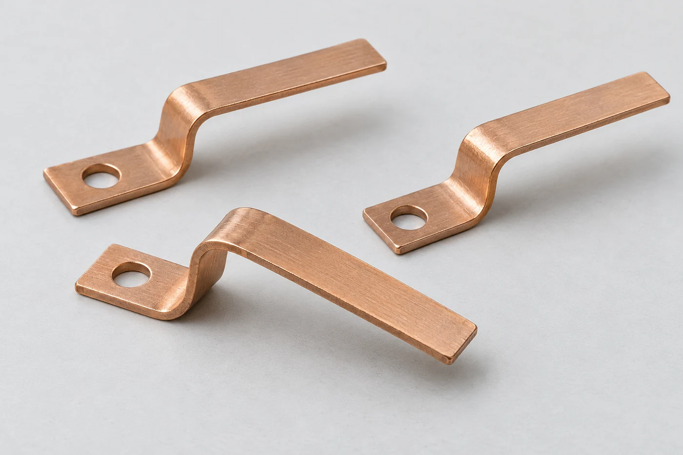
동합금 단자를 굽히면 바깥쪽은 늘어나고 안쪽은 눌리면서 소성변형이 생깁니다. 이 과정에서 굽힘부 가공경화가 발생해 국부 경도와 변형 저항이 달라집니다. 성형 뒤 남는 잔류응력과 스프링백은 최종 각도와 자유 높이를 바꾸고, 사용 중 접촉력과 영구 변형에 영향을 줍니다.
단자가 더 단단해졌다고 접촉력이 그만큼 커지는 것은 아닙니다. 탄성 범위의 접촉력은 형상·탄성계수·조립 변위가 정하고, 가공경화는 주로 항복 여유를 바꿉니다. 소재 질별부터 굽힘 반경·방향·열 이력까지 연결해 검토하고, 성형품의 하중–변위와 고온 접촉력 유지율로 기능을 확인해야 합니다.
굽힘부의 재료 상태 변화
굽힘부의 소성변형은 경도와 항복 거동을 바꾸며, 탄성 강성의 증가와는 구별합니다.
잔류응력과 스프링백
공구를 뗀 뒤 탄성 복원이 일어나고, 단면 안에 서로 균형을 이루는 잔류응력이 남습니다.
접촉력 유지와 응력완화
정해진 조립 변위에서도 시간·온도·재료 상태에 따라 접촉력이 낮아질 수 있습니다.
01굽힘부에서 일어나는 변형
굽힘 변형률의 분포
판재를 굽히면 두께 중앙 근처의 중립면을 기준으로 바깥쪽 섬유는 늘어나고 안쪽 섬유는 줄어듭니다. 변형률은 중립면에서 멀어질수록 커지며, 같은 두께에서는 안쪽 굽힘 반경이 작을수록 표면 변형률이 커집니다. 탄성 범위를 넘은 표면층부터 소성변형이 시작되고, 반경이 작아질수록 소성 영역이 두께 안쪽으로 넓어집니다.
판 두께 t와 안쪽 굽힘 반경 R을 사용하면 바깥 표면의 공칭 변형률을 ε ≈ t/(2R+t)로 가늠할 수 있습니다. 두께 중앙에 중립면을 둔 순수 굽힘 근사이므로, 같은 두께에서 R/t가 작을수록 표면 변형이 커지는 관계를 보여 줍니다. 실제 성형에서는 중립면 이동, 인장력, 마찰과 폭 방향 구속이 함께 작용합니다.
이 값을 인장시험의 파단 연신율과 바로 비교해 굽힘 합격 여부를 정하지는 않습니다. 인장시험과 굽힘은 변형 구배와 구속 조건이 다르기 때문입니다. 합금·질별별 최소 R/t, 시험편 방향과 폭, 굽힘 각도 및 표면 균열 판정 조건을 맞춰 적용합니다.
일반적으로 굽힘선이 압연 방향과 직각인 굽힘을 굿웨이, 나란한 굽힘을 배드웨이라고 부릅니다. 배드웨이는 같은 반경에서 균열에 더 민감한 경우가 있지만, 차이의 크기는 합금·질별·결정립과 집합조직에 따라 달라집니다. 방향성이 작은 소재도 있으므로 실제 공급 자료의 두 방향 굽힘값을 확인합니다.
도면과 전개도에는 길이 방향이라는 표현만 쓰지 말고 압연 방향 화살표와 굽힘선의 관계를 표시합니다. 같은 단자 안에서도 굽힘마다 방향이 달라질 수 있으며, 절단면 손상과 버가 인장측에 놓이는지도 함께 검토합니다.
굽힘 조건과 굽힘부 변형
| 굽힘 조건 | 굽힘부 변형에 미치는 영향 | 확인 항목 |
|---|---|---|
| 안쪽 굽힘 반경 R | 작을수록 표면 변형률과 소성 영역이 커짐 | 최소 R/t, 표면 균열 |
| 판 두께 t | 같은 반경에서 두꺼울수록 표면 변형률이 커짐 | R/t 비, 두께 편차 |
| 굽힘 방향 | 합금·질별에 따라 방향별 균열 민감도 차이 | 압연 방향 표시, 전개 배치 |
| 질별(냉간가공도) | 강도·열처리 상태에 따라 성형 여유 변화 | 질별 사양, 굽힘 시험 |
| 폭과 두께의 비 | 폭에 따라 횡방향 구속과 균열 조건 변화 | 형상별 굽힘 시험 |
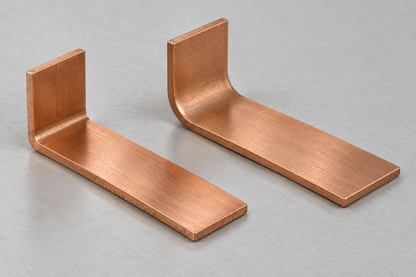
가공경화와 경도 분포
소성변형이 일어나면 금속 내부의 전위가 늘어나고 서로 얽혀 다음 변형에 대한 저항이 커집니다. 이것이 가공경화이며, 굽힘부의 소성 영역은 변형 전보다 항복강도와 경도가 높아집니다. 소재가 이미 압연으로 가공경화된 질별이라도 굽힘부는 추가 변형을 받아 주변과 다른 상태가 됩니다.
단순 굽힘에서는 변형률이 큰 안쪽·바깥쪽 표면 부근의 경화가 중립면 부근보다 큰 경향이 있습니다. 굽힘 중심에서 직선부로 멀어지면 추가 변형도 줄어듭니다. 다만 기존 압연 경화, 인장·압축의 비대칭, 코이닝과 마찰이 겹치면 분포가 달라지므로 대칭인 경도 곡선을 전제로 검사하지 않습니다.
경도 증가는 추가 소성변형에 대한 저항이 커졌다는 뜻이며, 탄성계수나 스프링 강성이 같은 비율로 증가했다는 뜻은 아닙니다. 이미 경화된 부위에 굽힘·교정·코이닝을 겹치면 남은 연성 여유를 소모할 수 있습니다. 외관이 같아도 변형 이력이 다르면 기능이 달라지므로, 같은 위치에 누적되는 소성변형과 절단면 상태를 함께 관리합니다.
굽힘 반경에 따른 굽힘부 변형률 분포
02잔류응력과 스프링백
하중 제거 뒤 남는 응력
굽힘 공구가 열리면 판재는 탄성 변형의 일부를 되돌립니다. 두께 방향으로 소성변형량이 서로 다른 층이 하나의 부품으로 연결되어 있기 때문에, 외력이 없어도 층 사이에 서로 균형을 이루는 응력이 남습니다. 잔류응력은 이 불균일한 변형과 복원이 남긴 내부 응력입니다.
단순한 탄성-완전소성 근사에서는 하중 상태의 응력에 반대 방향의 탄성 복원 응력을 더해 잔류응력을 구합니다. 그 결과 굽힘 때 인장을 받던 바깥 표면에는 압축 잔류응력이, 그 안쪽의 탄성-소성 경계 근처에는 인장 잔류응력이 남는 분포가 나타납니다. 실제 동합금은 가공경화와 바우싱거 효과 때문에 분포가 달라질 수 있어, 이 근사는 경향을 이해하는 기준으로 씁니다.
사용 중 부품이 다시 탄성 범위에서 휘면 잔류응력에 사용 응력을 더해 국부 응력을 검토할 수 있습니다. 같은 방향의 성분은 항복 여유를 줄이고 반대 방향의 성분은 줄어든 응력으로 작용할 수 있습니다. 그러나 재항복이 시작되면 응력이 재분배되므로 단순 덧셈만으로 이후 거동을 계산할 수 없습니다.
한 번의 성형과 역방향 교정이 섞인 단자는 인장시험에서 얻은 항복강도 하나만으로 판단하기 어렵습니다. 필요하면 성형 이력과 역방향 항복을 반영한 재료 모델을 사용하고, 실제 부품의 하중–변위·영구 변형으로 해석을 확인합니다.
굽힘부 두께 방향의 응력 분포
스프링백과 성형 각도
스프링백은 하중 제거 뒤 굽힘 각도가 벌어지는 현상입니다. 항복강도가 높고 탄성계수가 낮을수록, 굽힘 반경이 판 두께에 비해 클수록 탄성 복원의 비중이 커져 스프링백이 커집니다. 가공경화로 굽힘부 항복강도가 올라가면 같은 공구에서도 복원량이 달라질 수 있습니다.
스프링백 보정은 과굽힘, 굽힘 반경부 눌림(코이닝), 재굽힘 같은 방법으로 합니다. 과굽힘은 각도를 맞추는 데 효과적이지만 잔류응력 분포도 바꾸고, 반경부 눌림은 각도를 안정시키는 대신 국부 경화와 두께 감소를 늘립니다. 보정 방법을 바꿀 때는 각도뿐 아니라 접촉력과 균열을 함께 다시 확인합니다.
굽힌 뒤 반대 방향으로 교정하면 바우싱거 효과 때문에 역방향 항복이 더 낮은 응력에서 시작될 수 있습니다. 이를 제어한 과굽힘·되굽힘은 각도와 응력 분포를 조정하는 공정으로 활용할 수 있습니다. 다만 횟수와 변형량이 관리되지 않는 반복 교정은 결과를 불안정하게 만들 수 있으므로, 검증한 공정 순서와 허용 범위를 고정합니다.
스프링백 보정 방법과 굽힘부 상태
| 보정 방법 | 각도에 대한 효과 | 굽힘부 재료 상태에 미치는 영향 |
|---|---|---|
| 과굽힘 | 목표보다 더 굽혀 복원량을 상쇄 | 소성 영역 확대, 잔류응력 분포 변화 |
| 반경부 눌림(코이닝) | 반경부 소성변형으로 복원 감소 | 국부 경화와 두께 감소, 균열 위험 |
| 재굽힘·교정 | 각도 미세 조정 | 반대 방향 소성, 바우싱거 효과 |
| 굽힘 반경 축소 | 탄성 복원 비중 감소 | 표면 변형률과 균열 위험 증가 |
03접촉력과 굽힘부
접촉 스프링의 하중 경로
곧고 균일한 직사각형 외팔보가 끝단 하중을 받는 작은 탄성 변형에서는 k = Ebt³/(4L³), F = kδ로 강성과 힘을 가늠합니다. E는 탄성계수, b는 폭, t는 두께, L은 유효 길이, δ는 끝단 변위입니다. 이 관계는 두께와 길이의 편차가 힘을 크게 바꾸는 이유를 보여 줍니다.
실제 단자는 굽힘부, 테이퍼, 다중 접촉점과 고정 조건 때문에 단순 보와 다릅니다. 특히 접촉 위치가 이동하거나 큰 회전이 생기면 유효 길이와 하중 경로도 변합니다. 고정부 부근과 성형 반경부가 겹치는지 확인하고, 실제 형상의 하중–변위 곡선으로 설계 범위를 정합니다.
굽힘부 가공경화는 이 하중 경로의 항복 여유를 바꾸지만, 같은 형상·변위에서 탄성 접촉력을 자동으로 높이지는 않습니다. 국부 잔류응력과 역방향 항복까지 고려해야 경화된 부위의 실제 여유를 알 수 있습니다. 따라서 강도는 영구 변형을 피하는 조건으로, 강성과 조립 변위는 필요한 힘을 만드는 조건으로 나누어 검토합니다.
반복 삽입에서 최대 변위가 너무 크면 초기에 영구 변형이 생겨 자유 높이와 접촉력이 바뀔 수 있습니다. 많은 반복에 따른 피로 손상은 이 초기 세트와 구분해서 평가합니다. 첫 삽입, 정해진 전처리 횟수 뒤, 반복 시험 뒤의 힘과 자유 높이를 각각 기록하면 초기 자리잡기와 누적 손상을 구별하기 쉽습니다.
접촉편 휨과 굽힘부 응력, 응력완화
치수 편차와 접촉력 편차
접촉력은 판 두께와 굽힘 각도에 민감합니다. 두께가 조금만 달라져도 강성은 세제곱으로 변하고, 굽힘 각도 편차는 상대 단자와 만나는 위치의 초기 변위를 바꿉니다. 굽힘부 경화 정도가 로트마다 다르면 스프링백과 각도도 달라져 접촉력 편차로 이어집니다.
접촉력은 접촉면에 수직인 힘이며, 삽입 방향에서 측정하는 삽입력과 구별해야 합니다. 삽입력에는 접촉력뿐 아니라 진입 각도, 마찰, 도금과 윤활 상태가 포함되므로 두 값을 같은 것으로 취급하면 원인 분석이 어긋납니다.
측정은 실제 상대 단자 또는 그와 동등한 형상으로 하고, 기준면·접촉 위치·변위·속도·반복 횟수·시험 온도를 고정합니다. 양산에서는 소재 두께와 질별, 성형 각도와 자유 높이, 직접 측정한 접촉력을 함께 관리해야 치수 편차와 재료 상태의 영향을 나눠 볼 수 있습니다.
접촉력 변동 요인과 관리
| 변동 요인 | 접촉력에 미치는 경로 | 관리 방법 |
|---|---|---|
| 판 두께 | 강성(두께의 세제곱) | 입고 두께 측정, 공차 관리 |
| 굽힘 각도 | 초기 변위 | 각도·자유 높이 측정 |
| 소재 질별·로트 | 항복강도·스프링백 | 성적서, 경도·인장 확인 |
| 굽힘부 경화 정도 | 스프링백·항복 여유 | 단면 경도, 공정 조건 고정 |
| 도금 두께 | 마찰·상대 치수와 삽입력 변화 | 두께·표면 상태, 접촉력과 삽입력 구분 |
04응력완화와 온도
응력완화의 원리
응력완화는 전체 변형을 일정하게 유지할 때 시간이 지나며 응력이 줄어드는 현상입니다. 단자가 상대 부품에 의해 눌린 상태에서는 시간 의존 변형이 증가하면서 탄성 변형이 줄어, 같은 조립 변위에서 내는 접촉력이 낮아질 수 있습니다. 온도와 초기 응력 수준은 진행 속도에 큰 영향을 줍니다.
하중을 일정하게 두고 변형이 늘어나는 크리프와 시험 조건은 다르지만, 둘 다 시간 의존 변형과 관련됩니다. 단자를 풀었을 때의 영구 처짐과 끼워 둔 상태의 접촉력 저하를 같은 측정값으로 혼용하지 않고, 평가 방법에 맞춰 연결해서 해석합니다.
응력완화 자료는 합금명만 같다고 직접 비교할 수 없습니다. 질별·열처리 상태, 시험 방향, 초기 응력 또는 항복강도 대비 응력비, 온도·시간과 측정 방법을 함께 확인합니다. 압연 방향과 직각 방향의 차이는 소재에 따라 달라지므로 실제 단자 배치와 일치하는 자료를 우선합니다.
접촉부 온도는 주변 온도만으로 정해지지 않습니다. 통전 발열과 주변 부품의 열 전달, 수지 하우징의 변형과 열팽창도 사용 중 조립 변위를 바꿀 수 있습니다. 소재의 일정 변위 시험과 완성 커넥터의 통전·열 시험을 연결해 검토해야 하는 이유입니다.
냉간가공도가 높아지면 강도는 커질 수 있지만 응력완화 저항이 같은 비율로 좋아지는 것은 아닙니다. 일부 동합금은 최종 압연 뒤의 응력완화 처리나 제어된 시효 상태로 힘 유지 특성을 개선합니다. 공급사가 정의한 최종 상태를 확인하고, 동일 초기 응력 조건에서 비교한 유지율과 설계에 필요한 절대 힘을 함께 봅니다.
굽힘부가 응력완화에 주는 영향
성형된 반경부가 높은 사용 응력을 받는 구간과 겹치면, 그 부위의 변형 이력과 잔류응력이 접촉력 유지에 중요해집니다. 다만 완화가 한 점에서만 진행되는 것은 아니며, 스프링 전체의 응력 분포와 온도, 지지 조건에 따라 힘이 재분배됩니다.
굽힘부는 냉간가공된 원판재와 다른 전위 구조와 국부 항복 거동을 가질 수 있습니다. 판재의 유지율을 성형품에 그대로 대입하기보다 실제 반경·방향·후공정 상태를 반영한 부품 시험으로 차이를 확인합니다.
성형 뒤 열처리는 합금과 공급 질별에 맞춰 목적을 구분합니다. 잔류응력을 줄이는 처리와 석출물을 형성해 강도를 얻는 시효 처리는 같은 공정이 아닙니다. 이미 최종 열처리된 소재에 임의의 온도를 적용하면 연화나 과시효가 생겨 힘이 낮아질 수 있습니다.
열처리를 채택할 때에는 온도·유지 시간·분위기뿐 아니라 성형 전후의 적용 시점과 도금 순서를 정합니다. 처리 전후의 경도, 자유 높이, 하중–변위, 접촉력 유지율과 표면 상태를 비교해 목적에 맞는 조건인지 확인합니다.
접촉력 유지율은 같은 측정 조건에서 F후/F초기 × 100%로 정의할 수 있습니다. 초기 힘과 가열 뒤 힘을 서로 다른 온도나 변위에서 재면 열팽창과 탄성계수 변화가 완화 손실에 섞입니다. 가열 중 측정인지, 정해진 냉각 절차 뒤 측정인지와 재삽입 여부를 미리 정합니다.
판재 외팔보 시험에서는 정해진 처짐으로 유지한 뒤 영구 처짐을 이용해 잔존 응력을 평가할 수 있습니다. 이 처짐 기반 환산은 탄성 강성과 시험 지그 조건이 유지되는 범위에서 적용합니다. 부품 시험은 실제 상대 형상으로 유지하고 접촉력·자유 높이·접촉저항을 함께 확인하며, 표면 피막·도금·마모도 영향을 주는 저항 증가를 곧바로 응력완화량으로 환산하지 않습니다.
응력완화 영향 인자와 확인 방법
| 영향 인자 | 접촉력 유지에 미치는 영향 | 확인 방법 |
|---|---|---|
| 사용 온도 | 높을수록 진행이 빠름 | 사용 온도 기준 가열 시험 |
| 초기 응력 수준 | 응력 수준에 따라 진행 속도와 손실 변화 | 설계 응력비 검토 |
| 합금·질별 | 계열과 열처리 상태에 따라 차이 | 소재 자료, 부품 시험 |
| 압연 방향 | 방향에 따라 결과가 다름 | 시험 방향 확인, 배치 방향 |
| 굽힘부 상태 | 잔류응력·경화로 판재와 다른 거동 | 성형품 단위 시험 |
| 성형 후 열처리 | 처리 목적·조건에 따라 안정화 또는 연화 | 최종 상태의 힘·치수·경도 비교 |
외팔보 응력완화 시험
05경도와 잔류응력의 측정
굽힘부 단면 경도
굽힘부 가공경화는 부품을 굽힘 중심에서 절단해 연마한 단면에 작은 하중의 비커스 압흔을 찍어 확인합니다. 바깥 표면에서 안쪽 표면까지 두께 방향으로 여러 점을 찍고, 같은 방법으로 직선부를 측정해 경도 차이를 비교합니다.
얇은 단자에서는 압흔 사이 간격과 가장자리 거리를 규격 조건대로 지켜야 이웃 압흔이나 가장자리의 영향을 피할 수 있습니다. 시험 하중이 너무 작으면 측정 편차가 커지고, 너무 크면 두께 방향으로 충분한 점을 찍기 어렵습니다. 절단·연마 중 발열과 눌림이 표면 경도를 바꾸지 않도록 시편 준비 조건도 함께 고정합니다.
경도 분포는 반경·질별·공정 순서 변경을 비교하는 데 유용하지만, 경도만으로 잔류응력이나 접촉력 유지율을 역산할 수는 없습니다. 국부 경도에서 항복강도로 바꾸려면 해당 합금과 상태에 맞는 상관관계가 필요합니다. 절대 경도와 함께 직선부 대비 변화량·측정 위치·분포를 기록하고 기능 시험과 연결합니다.
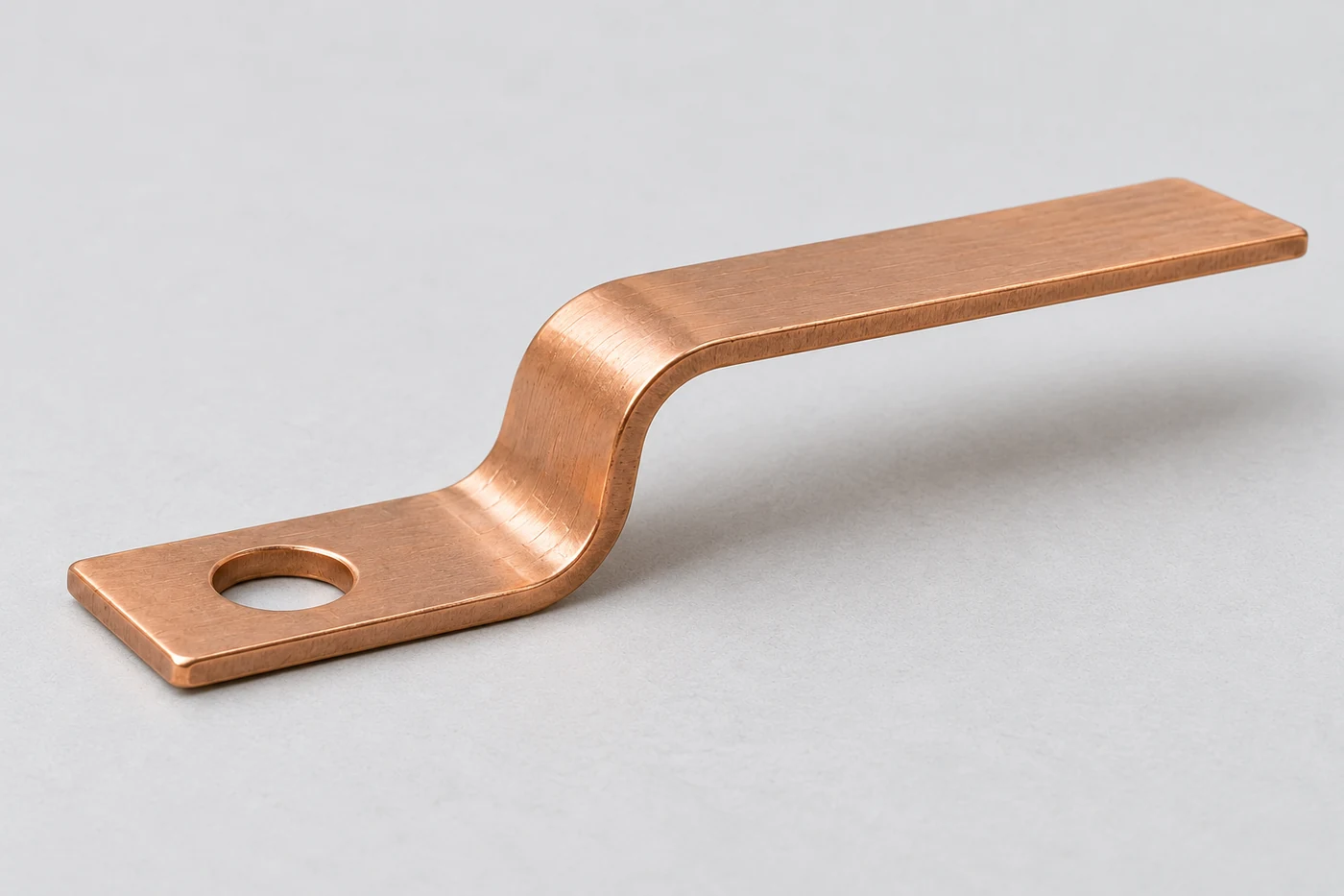
잔류응력과 기능 측정
X선 회절은 격자 간격 변화를 이용해 조사한 영역의 잔류응력을 평가합니다. 얇고 굽은 단자에서는 빔 크기, 곡률, 정렬, 결정립과 집합조직이 결과에 영향을 주며, 도금층과 모재 중 어느 상을 측정했는지도 확인해야 합니다. 일반적인 표면 측정값이 두께 전체의 응력 분포를 대표하는 것은 아닙니다.
깊이 방향 평가가 필요하면 단계적 층 제거에 따른 응력 재분배를 보정하거나, 적합한 고에너지 회절 방법을 검토합니다. 또한 경도용 단면을 절단하면 원래 잔류응력이 재분배될 수 있으므로, 단면 경도 시험편을 그대로 원래 응력 상태의 증거로 사용하지 않습니다.
일상적인 공정 관리는 각도·자유 높이·하중–변위·영구 변형·가열 뒤 힘 유지율처럼 기능에 직접 연결되는 항목으로 구성할 수 있습니다. 잔류응력 직접 측정은 원인 분석이나 중요한 공정 변경의 검증에 더해 활용합니다. 같은 기능값이라도 다른 원인으로 나올 수 있으므로 치수·경도·공정 이력을 함께 비교합니다.
측정 방법별 확인 내용
| 측정 방법 | 알 수 있는 것 | 주의점 |
|---|---|---|
| 단면 미소 비커스 경도 | 두께·길이 방향 경도 분포 | 압흔 간격, 시편 준비 |
| X선 회절 잔류응력 | 표면 잔류응력 | 곡률·빔 크기·집합조직·측정 상 |
| 굽힘 각도·자유 높이 | 스프링백, 초기 변위 | 측정 기준면 고정 |
| 변위-하중 곡선 | 유효 강성과 비선형·영구 변형 | 지그 형상·속도·마찰·언로딩 확인 |
| 반복 삽입 시험 | 영구 변형, 접촉력 저하 | 상대 형상 일치 |
| 가열 응력완화 시험 | 접촉력 유지율 | 온도·시간·변위·측정 온도·재삽입 여부 |
06소재·공정 선정과 도면 요구사항
소재와 질별 선정
소재는 필요한 접촉력과 전도성, 사용 온도에서의 힘 유지, 최소 굽힘 반경을 동시에 만족하도록 고릅니다. 가장 높은 강도의 질별을 고르는 것만으로 최적 설계가 되지는 않습니다. 강도를 높이며 굽힘 여유·스프링백·도금 공정과의 적합성이 나빠지는지 함께 검토합니다.
황동·인청동처럼 고용 강화와 냉간가공을 활용하는 계열, Cu-Ni-Si와 베릴륨동처럼 석출경화를 활용하는 계열은 강화 방식과 최종 상태가 다릅니다. 석출경화형도 이미 고강도 상태로 공급되는지, 성형 뒤 시효가 필요한 상태인지에 따라 공정이 달라집니다. 합금명만으로 굽힘성과 응력완화 순위를 정하지 않습니다.
후보 비교표에는 동일 두께의 방향별 최소 R/t, 항복강도와 전도도, 최종 질별의 응력완화 자료를 같이 놓습니다. 표준 인장 성적만으로 부족한 작은 반경부는 실제 전개 형상으로 시험하고, 필요한 기능을 만족하는 소재·질별·형상의 조합을 선택합니다.
공정 순서와 열처리
예비 굽힘과 최종 굽힘으로 공정을 나누면 소재 흐름과 공구 접촉을 제어하기 쉬워질 수 있습니다. 그러나 최종 반경과 형상이 같다면 공정을 나눈 것만으로 필요한 표면 변형률이 사라지지는 않습니다. 반복 교정과 되굽힘이 더해지면 변형 이력이 오히려 복잡해질 수 있습니다.
굽힘부 가까운 코이닝·엠보싱·펀칭, 절단면 손상과 윤활 조건까지 함께 검토합니다. 수정 공정은 최종 각도뿐 아니라 균열·표면 손상·국부 경도·하중–변위가 어떻게 달라지는지 비교해 채택합니다.
최종 기능 검증은 부품이 실제 납품되는 후공정 상태에서 실시합니다. 열처리, 도금에 수반되는 열 노출, 리플로와 접합 공정은 온도·시간에 따라 모재와 표면을 바꿀 수 있습니다. 공정 이름만으로 연화 여부를 판단하지 말고 실제 열 이력과 최종 경도·치수·접촉력을 확인합니다.
도면과 승인 기준
도면과 사양서에는 소재 합금·질별·두께 공차와 함께 굽힘 방향(압연 방향 표시), 최소 안쪽 반경, 기능 각도와 자유 상태 높이를 적습니다. 접촉력은 측정 변위·측정 위치·상대 형상과 함께 범위로 지정하고, 필요하면 사용 온도 기준의 응력완화 조건을 함께 둡니다.
양산 승인에서는 초품의 굽힘부 외관·단면 경도, 각도·자유 높이, 하중–변위와 반복 삽입·가열 뒤 힘 유지율을 기준 데이터로 남깁니다. 개발 검증 항목과 일상 검사 항목을 구분하고, 측정 반복성·시편 수·위치·판정 조건을 정합니다. 소재 로트·질별·금형·열 이력이 바뀌면 영향에 맞는 항목을 같은 방법으로 재확인합니다.
도면·사양 요구 항목
| 항목 | 지정 내용 |
|---|---|
| 소재 | 합금, 질별, 두께 공차, 압연 방향 |
| 굽힘부 | 최소 안쪽 반경, 굽힘 방향, 외관 기준 |
| 기능 치수 | 굽힘 각도, 자유 상태 높이, 측정 기준면 |
| 접촉력 | 측정 변위·위치·상대 형상, 허용 범위 |
| 신뢰성 | 반복 삽입 횟수, 가열 온도·시간, 유지율 기준 |
| 공정 변경 | 재시험 항목과 비교 방법 |
English Edition · Work Hardening at Bends: Hardness, Residual Stress and Stress Relaxation in Copper-Alloy Terminals
Bending a copper-alloy terminal stretches its outer fibers and compresses its inner fibers, producing plastic deformation. Work hardening at the bend changes local hardness and resistance to further deformation. Residual stress and springback after forming alter the final angle and free height, influencing contact force and permanent set in service.
A harder terminal does not automatically produce a proportionately higher contact force. Within the elastic range, force is governed by geometry, elastic modulus and mating deflection; work hardening primarily changes the margin to yielding. Temper, bend radius, orientation and thermal history must therefore be considered together, with load–deflection and elevated-temperature force-retention tests on formed parts.
Changed material condition
Plastic deformation changes hardness and yielding at the bend; this is distinct from an increase in elastic stiffness.
Residual stress and springback
Elastic recovery follows tool removal, leaving self-equilibrating residual stresses within the section.
Contact force and relaxation
Even at a fixed mating deflection, contact force can decrease with time, temperature and material condition.
01Deformation at the Bend
Distribution of Bending Strain
When a strip is bent, the outer fibers stretch and the inner fibers shorten about a neutral surface near mid-thickness. Strain grows with distance from the neutral surface, and for the same thickness a smaller inside bend radius gives a larger surface strain. Plastic deformation starts in the surface layers that exceed the elastic range, and the plastic zone spreads deeper into the thickness as the radius decreases.
Using strip thickness t and inside bend radius R, the nominal outer-surface strain can be estimated as ε ≈ t/(2R+t). This pure-bending approximation places the neutral surface at mid-thickness and shows why a smaller R/t gives greater surface deformation. Actual forming also involves neutral-surface movement, tensile loading, friction and transverse constraint.
This value should not be compared directly with tensile elongation at fracture to declare a bend acceptable. Tensile and bend tests have different strain gradients and constraints. Use the minimum R/t for the alloy and temper with matching specimen orientation, width, bend angle and surface-crack acceptance conditions.
A bend line perpendicular to the rolling direction is commonly called good-way bending; a parallel bend line is called bad-way bending. Bad-way bends can be more crack-sensitive at the same radius, but the difference depends on alloy, temper, grain structure and texture. Some materials show little directional difference, so both bend directions in the supplier data must be checked.
Drawings and blank layouts should show the rolling-direction arrow relative to each bend line, rather than simply saying longitudinal. Different bends within one terminal may have different orientations. Also review whether a damaged cut edge or burr is placed on the tensile side.
Bend conditions and deformation at the bend
| Condition | Effect on deformation at the bend | Check |
|---|---|---|
| Inside radius R | Smaller radius increases surface strain and plastic zone | Minimum R/t, surface cracks |
| Thickness t | At the same radius, thicker strip has higher surface strain | R/t ratio, thickness variation |
| Orientation | Directional crack sensitivity depends on alloy and temper | Rolling-direction marking, blank layout |
| Temper (cold work) | Forming margin varies with strength and heat-treated condition | Temper specification, bend test |
| Width-to-thickness ratio | Width changes transverse constraint and crack conditions | Bend test on the actual shape |
Work Hardening and Hardness Distribution
Plastic deformation multiplies dislocations inside the metal, and their entanglement raises resistance to further deformation. This is work hardening, and the plastic zone of a bend ends up with higher yield strength and hardness than before forming. Even when the strip is a temper already work-hardened by rolling, the bend receives additional deformation and ends up in a different condition from its surroundings.
In simple bending, hardening tends to be greater near the inner and outer surfaces, where strain is higher, than near the neutral surface. Additional deformation also diminishes from the bend center toward the straight legs. Prior rolling work, tension–compression asymmetry, coining and friction can alter the distribution, so inspection should not assume a symmetric hardness profile.
An increase in hardness indicates greater resistance to further plastic deformation; it does not mean that elastic modulus or spring stiffness has increased in the same proportion. Further bending, straightening or coining at an already hardened location can consume the remaining ductility. Parts with the same appearance can function differently after different strain histories, so accumulated plastic deformation and cut-edge condition must be controlled together.
Bending Strain Distribution by Bend Radius
02Residual Stress and Springback
Stress That Remains After Unloading
When the bending tool opens, the strip recovers part of its elastic deformation. Layers with different amounts of plastic strain remain connected within one part, leaving self-equilibrating stresses even without an external load. Residual stress is the internal stress left by this nonuniform deformation and recovery.
In a simple elastic-perfectly plastic approximation, residual stress is obtained by adding the elastic recovery stress of the opposite sign to the stress under load. The result is compressive residual stress at the outer surface that was in tension during bending, and tensile residual stress near the elastic-plastic boundary just inside it. Real copper alloys can deviate from this because of work hardening and the Bauschinger effect, so the approximation is used as a guide to the trend.
While a part reloads within the elastic range, service stresses can be superposed on the residual-stress field to assess local stress. Components with the same sign can reduce the margin to yielding, while opposing components can reduce the resulting stress. Once renewed yielding begins, stresses redistribute and simple addition no longer describes the subsequent behavior.
A single tensile yield-strength value may therefore be insufficient for terminals that undergo both forming and reverse straightening. Where needed, use a material model that captures forming history and reverse yielding, and verify the analysis against actual part load–deflection and permanent set.
Stress Distribution Through the Bend Thickness
Springback and Formed Angle
Springback is the opening of the bend angle after unloading. The higher the yield strength, the lower the elastic modulus, and the larger the bend radius relative to thickness, the larger the share of elastic recovery and the greater the springback. When work hardening raises the yield strength at the bend, the amount of recovery can change even with the same tooling.
Springback is compensated by overbending, coining of the bend radius, or rebending. Overbending is effective for hitting the angle but also changes the residual stress distribution, while coining the radius stabilizes the angle at the cost of more local hardening and thinning. When the compensation method changes, contact force and cracking are rechecked along with the angle.
Reverse straightening after bending can initiate reverse yielding at a lower stress because of the Bauschinger effect. Controlled overbending and reverse bending can be used to adjust the angle and stress distribution. Repeated corrections with uncontrolled strain and cycle count can instead make the outcome unstable, so use a qualified process sequence and defined operating limits.
Springback compensation and the condition of the bend
| Method | Effect on angle | Effect on material condition at the bend |
|---|---|---|
| Overbending | Bend past target to offset recovery | Larger plastic zone, changed residual stress |
| Coining the radius | Plastic deformation of the radius reduces recovery | Local hardening and thinning, crack risk |
| Rebending, straightening | Fine angle adjustment | Reverse plasticity, Bauschinger effect |
| Smaller bend radius | Lower share of elastic recovery | Higher surface strain and crack risk |
03Contact Force and the Bend
Load Path of the Contact Spring
For small elastic deflection of a straight, uniform rectangular cantilever under an end load, stiffness and force can be estimated as k = Ebt³/(4L³), F = kδ. E is elastic modulus, b is width, t is thickness, L is effective length and δ is end deflection. This relation explains why thickness and length variations strongly affect force.
Real terminals differ from this simple beam because of bends, taper, multiple contact points and support conditions. Moving contact locations and large rotations also change effective length and the load path. Check whether the highly loaded region near the support overlaps a formed radius, and establish the operating range from the actual geometry’s load–deflection curve.
Work hardening changes the yield margin along this load path, but does not automatically raise elastic contact force at unchanged geometry and deflection. Local residual stress and reverse yielding must also be considered to assess the available margin. Treat strength as a condition for avoiding permanent set, and stiffness and mating deflection as the conditions that produce the required force.
Excessive peak deflection during insertion can cause early permanent set, changing free height and contact force. Fatigue damage over many cycles must be evaluated separately from this initial set. Recording force and free height at first insertion, after a defined conditioning sequence and after cycling helps distinguish initial settling from accumulated damage.
Contact-Arm Deflection, Stress at the Bend and Relaxation
Dimensional Variation and Contact-Force Variation
Contact force is sensitive to thickness and bend angle. A small thickness change alters stiffness by its cube, and angle variation changes the initial deflection where the arm meets the mating part. If the degree of hardening at the bend differs between lots, springback and angle also differ, leading to contact-force variation.
Contact force acts normal to the contact surface and must be distinguished from insertion force measured along the insertion direction. Insertion force also includes entry geometry, friction, plating and lubrication effects. Treating these forces as interchangeable can lead to an incorrect diagnosis.
Use the actual mating part or an equivalent geometry, with fixed datums, contact location, deflection, speed, cycle count and test temperature. Production control should combine strip thickness and temper, formed angle and free height, and direct contact-force measurement to separate dimensional variation from changes in material condition.
Sources of contact-force variation and their control
| Source | Path to contact force | Control |
|---|---|---|
| Thickness | Stiffness (cube of thickness) | Incoming thickness check, tolerance control |
| Bend angle | Initial deflection | Angle and free-height measurement |
| Temper and lot | Yield strength, springback | Certificates, hardness and tensile checks |
| Hardening at the bend | Springback, yield margin | Section hardness, fixed process conditions |
| Plating thickness | Friction, mating dimensions and insertion force | Thickness and surface condition; distinguish contact from insertion force |
04Stress Relaxation and Temperature
Principle of Stress Relaxation
Stress relaxation is the decrease in stress over time while total deformation is held constant. In a terminal held against a mating part, increasing time-dependent strain can reduce the elastic strain and therefore the contact force at the same mating deflection. Temperature and initial stress level strongly influence the rate.
The boundary condition differs from creep, where deformation increases under a constant load, although both involve time-dependent deformation. Permanent set after releasing the terminal and force loss while it remains mated should not be treated as the same measured quantity; relate them using the chosen evaluation method.
Relaxation data cannot be compared on alloy name alone. Check temper and heat-treatment condition, test direction, initial stress or fraction of yield strength, temperature, duration and measurement method. The difference between rolling and transverse directions is material-dependent, so prioritize data that match the terminal layout.
Contact temperature is not determined by ambient temperature alone. Current heating, heat transfer from nearby components, and deformation or thermal expansion of the polymer housing can also change the mating deflection in service. This is why fixed-deflection material tests must be considered together with electrical and thermal tests on the complete connector.
More cold work can increase strength without improving relaxation resistance in the same proportion. Some copper alloys achieve improved force retention through a post-rolling stress-relief treatment or a controlled aged condition. Confirm the supplier-defined final condition, and consider both retention under comparable initial-stress conditions and the absolute force required by the design.
How the Bend Affects Stress Relaxation
Where a formed radius overlaps a region of high service stress, its strain history and residual stress become important to force retention. Relaxation is not confined to a single point: force redistributes according to the stress distribution, temperature and support conditions of the entire spring.
The bend can have a dislocation structure and local yielding behavior that differ from those of the original cold-rolled strip. Rather than applying a flat-strip retention value directly to the part, use component tests that represent the actual radius, orientation and downstream processing.
The purpose of post-forming heat treatment must match the alloy and supplied temper. A treatment intended to reduce residual stress is not the same as ageing intended to strengthen the alloy through precipitation. Applying an arbitrary temperature to material already in its final heat-treated condition can cause softening or overageing and reduce force.
When heat treatment is selected, define temperature, hold time and atmosphere together with its position relative to forming and plating. Compare hardness, free height, load–deflection, force retention and surface condition before and after treatment to confirm that the process achieves its intended purpose.
Force retention can be defined under matching measurement conditions as Fafter/Finitial × 100%. Measuring the initial and final forces at different temperatures or deflections mixes thermal expansion and modulus changes with relaxation loss. Define whether force is measured hot or after a specified cooling procedure, and whether the part is remated.
A strip cantilever method can estimate retained stress from permanent set after holding a prescribed deflection. This deflection-based conversion applies while elastic stiffness and fixture conditions remain consistent. Component tests use the actual mating geometry and examine contact force, free height and contact resistance together; because films, plating and wear also affect resistance, resistance increase must not be converted directly into an amount of stress relaxation.
Factors in stress relaxation and how to check them
| Factor | Effect on force retention | Check |
|---|---|---|
| Service temperature | Faster at higher temperature | Heating test at service temperature |
| Initial stress level | Stress level changes relaxation rate and loss | Design stress-ratio review |
| Alloy and temper | Differs by family and heat-treatment condition | Material data, part tests |
| Rolling direction | Results differ by direction | Check test direction and layout |
| Condition of the bend | Residual stress and hardening change behavior from flat strip | Tests on formed parts |
| Post-forming heat treatment | Stabilization or softening depending on purpose and conditions | Compare force, dimensions and hardness in the final condition |
Cantilever Stress-Relaxation Test
05Measuring Hardness and Residual Stress
Section Hardness at the Bend
Work hardening at the bend is checked by sectioning the part at the bend center, polishing the section and making low-force Vickers indentations. Several points are placed through the thickness from the outer to the inner surface, and the straight portion is measured the same way to compare the difference in hardness.
In thin terminals, indentation spacing and edge distance must follow the standard’s conditions to avoid influence from neighboring indents or the edge. Too low a test force increases scatter, while too high a force makes it hard to fit enough points through the thickness. Specimen preparation conditions are also fixed so that heat and pressure during cutting and polishing do not change the surface hardness.
A hardness profile is useful for comparing radius, temper and process changes, but hardness alone cannot recover residual stress or force retention. Converting local hardness into yield strength requires a correlation appropriate to the alloy and condition. Record absolute hardness, the change relative to the straight portion, measurement locations and the distribution, then relate these to functional tests.
Residual Stress and Functional Measurements
X-ray diffraction evaluates residual stress from changes in lattice spacing within the illuminated region. For a thin curved terminal, beam size, curvature, alignment, grain structure and texture affect the result; it is also necessary to establish whether the coating or the substrate phase was measured. A conventional surface measurement does not represent the complete through-thickness stress distribution.
Depth profiling may require correction for stress redistribution during incremental layer removal, or an appropriate high-energy diffraction method. Sectioning for hardness measurements can itself redistribute residual stress, so a sectioned hardness specimen should not be treated as direct evidence of the original stress state.
Routine process control can focus on quantities directly tied to function: angle, free height, load–deflection, permanent set and force retention after heating. Direct residual-stress measurement can supplement root-cause analysis or validation of a major process change. Because different causes can produce similar functional results, compare dimensions, hardness and process history together.
What each measurement shows
| Method | What it shows | Caution |
|---|---|---|
| Section micro-Vickers hardness | Hardness distribution through thickness and length | Indent spacing, specimen preparation |
| X-ray diffraction residual stress | Surface residual stress | Curvature, beam size, texture and measured phase |
| Bend angle, free height | Springback, initial deflection | Fixed datum |
| Deflection-force curve | Effective stiffness, nonlinearity and permanent set | Fixture, speed, friction and unloading check |
| Repeated insertion test | Permanent set, force loss | Matching mating geometry |
| Heated relaxation test | Force retention | Temperature, time, deflection, measurement temperature and remating |
06Material and Process Selection and Drawing Requirements
Choosing the Alloy and Temper
Select the material to meet contact-force and conductivity requirements, force retention at service temperature and the minimum bend radius together. Choosing the highest-strength temper alone does not establish an optimum design. Check whether increasing strength compromises bendability, springback control or compatibility with the plating process.
Families such as brass and phosphor bronze that use solid-solution strengthening and cold work differ from precipitation-strengthened families such as Cu-Ni-Si and beryllium copper. Even within a precipitation-strengthened family, the process depends on whether the strip is supplied in a final high-strength condition or in a condition intended for ageing after forming. Alloy name alone cannot rank bendability or stress-relaxation performance.
Compare minimum R/t in both directions at the same thickness, yield strength, conductivity and relaxation data for the final temper. Test tight radii using the actual blank geometry when tensile certificates alone are insufficient, and choose the combination of material, temper and geometry that meets the functional requirements.
Process Sequence and Heat Treatment
Dividing the operation into pre-bending and final bending can make material flow and tool contact easier to control. It does not eliminate the surface strain required to reach the same final radius and geometry. Additional straightening and reverse bending can instead make the strain history more complex.
Review nearby coining, embossing and punching, cut-edge damage and lubrication together with the bend. Accept a revised process by comparing cracking, surface damage, local hardness and load–deflection as well as the final angle.
Final functional validation should use the condition in which the part will actually be delivered. Heat treatment, thermal exposure associated with plating, reflow and joining can change the substrate and surface depending on temperature and duration. Do not infer softening from the process name alone; verify the actual thermal history and final hardness, dimensions and contact force.
Drawings and Acceptance Criteria
The drawing and specification state the alloy, temper and thickness tolerance together with bend orientation (rolling-direction marking), minimum inside radius, functional angle and free height. Contact force is specified as a range together with the measuring deflection, position and mating geometry, and stress-relaxation conditions at service temperature are added where needed.
At production approval, retain baseline data for bend appearance and section hardness, angle and free height, load–deflection, and force retention after cycling and heating. Distinguish development validation from routine inspection, and define measurement repeatability, sample count, location and acceptance conditions. Recheck the relevant items by the same methods when material lot, temper, tooling or thermal history changes.
Drawing and specification items
| Item | What to specify |
|---|---|
| Material | Alloy, temper, thickness tolerance, rolling direction |
| Bends | Minimum inside radius, orientation, appearance criteria |
| Functional dimensions | Bend angle, free height, datum |
| Contact force | Measuring deflection, position, mating geometry, range |
| Reliability | Insertion cycles, heating temperature and time, retention criterion |
| Process changes | Retest items and comparison method |
추가 정보
검색엔진용 요약
굽힘부 가공경화는 동합금 단자를 굽힐 때 소성변형 영역의 경도와 항복강도가 올라가는 현상입니다. 하중을 제거한 뒤 남는 잔류응력과 함께 스프링백, 접촉력과 고온 응력완화에 영향을 주므로, 질별·굽힘 방향·반경·공정 순서를 정하고 단면 경도와 접촉력 유지율을 성형품으로 확인합니다.
핵심 포인트 정리
- 굽힘부 바깥쪽은 늘어나고 안쪽은 눌리며, 표면 변형률은 대략 t/(2R+t)로 가늠합니다.
- 소성변형은 경도와 항복 거동을 바꾸지만 탄성 강성의 증가와는 구별합니다.
- 단순 굽힘 모형의 잔류응력 분포는 실제 소재의 경화·역방향 항복과 공정 이력에 따라 달라집니다.
- 스프링백 보정 방법은 각도뿐 아니라 굽힘부의 경화와 잔류응력 분포도 바꿉니다.
- 접촉편의 최대 굽힘 모멘트는 고정부 쪽에 걸리며 이 위치가 성형 굽힘부와 겹치는 경우가 많습니다.
- 응력완화는 일정 변위에서 시간이 지나며 접촉력이 줄어드는 현상으로, 온도·초기 응력·합금·방향의 영향을 받습니다.
- 판재 시험값과 성형품의 거동은 다를 수 있어 성형품 단위의 접촉력·가열 시험으로 판정합니다.
- 도면에는 질별·굽힘 방향·최소 반경·접촉력 측정 조건·응력완화 조건을 함께 적습니다.
FAQ
굽힘부가 단단해지면 접촉력이 높아지나요?
가공경화는 주로 항복 거동을 바꾸며 탄성계수나 강성이 같은 비율로 증가하는 것은 아닙니다. 접촉력은 형상·탄성계수·조립 변위로 정해지고 잔류응력과 역방향 항복도 여유에 영향을 주므로, 실제 성형품의 하중–변위로 확인합니다.
굽힘 반경을 작게 하면 무엇이 달라지나요?
같은 두께에서 반경을 줄이면 표면 변형률이 커지고 단순 굽힘에서는 탄성 복원의 상대적 비중이 줄어드는 경향이 있습니다. 잔류응력이 무조건 커진다고 단정할 수는 없으며, 균열과 표면 거칠어짐을 방향별 최소 R/t와 실제 성형 조건으로 확인합니다.
굿웨이와 배드웨이는 어떻게 구분하나요?
굽힘선이 압연 방향과 직각이면 굿웨이, 나란하면 배드웨이라고 부릅니다. 방향에 따른 차이는 합금·질별에 따라 달라지므로 공급 자료의 두 방향 값을 확인하고 도면에 압연 방향과 굽힘선을 함께 표시합니다.
잔류응력은 접촉편에 어떤 영향을 주나요?
탄성 범위의 재하에서는 사용 응력과 합쳐져 국부 항복 여유를 바꿉니다. 재항복 뒤에는 응력이 재분배되므로 단순 덧셈만으로 판단하지 않고, 반복 삽입·언로딩과 가열 뒤 기능을 함께 확인합니다.
응력완화는 어떻게 시험하나요?
판재 외팔보 시험에서는 정해진 처짐을 유지한 뒤 영구 처짐으로 잔존 응력을 평가할 수 있습니다. 부품은 실제 상대 형상으로 유지하고 초기·가열 뒤 힘을 같은 변위와 온도 조건에서 비교합니다. 냉각·재삽입 절차를 정하고, 접촉저항 변화는 표면 영향과 구분합니다.
성형 뒤 열처리를 하면 좋아지나요?
합금과 공급 질별에 따라 달라집니다. 잔류응력 완화와 석출경화용 시효의 목적을 구분하고, 이미 최종 처리된 소재를 임의로 가열하지 않습니다. 공급사 권장 조건 안에서 최종 경도·치수·하중–변위와 힘 유지율로 검증합니다.
굽힘부 경도는 어떻게 측정하나요?
굽힘 중심에서 절단해 연마한 단면에 작은 하중의 비커스 압흔을 두께 방향으로 찍고 직선부와 비교합니다. 압흔 간격과 가장자리 거리, 시편 준비 조건을 고정해야 비교가 의미 있습니다.
단자 굽힘부 검토에는 어떤 정보가 필요한가요?
단자 도면과 소재 합금·질별·두께, 굽힘 방향과 반경, 요구 접촉력과 측정 조건, 사용 온도와 수명 조건, 이어지는 도금·열처리 공정을 준비하면 검토가 구체화됩니다.
관련 주제 확장 설명
바우싱거 효과
한 방향으로 소성변형한 금속은 역방향으로 더 낮은 응력에서 항복할 수 있습니다. 제어된 역방향 교정은 각도와 응력 분포 조정에 활용할 수 있지만, 변형량·횟수가 불명확한 반복 교정은 결과를 불안정하게 만들 수 있어 공정 조건을 검증해야 합니다.
석출경화형 합금
석출경화형도 공급 질별과 최종 시효 상태에 따라 굽힘성과 응력완화가 달라집니다. 성형 뒤 시효가 필요한 상태인지 이미 최종 고강도 상태인지 확인하고, 요구 전도도·굽힘 반경·힘 유지율을 함께 비교합니다.
판재 시험과 성형품 시험
소재 비교는 판재 시험으로, 설계 판정은 성형품 시험으로 나눠 보면 굽힘부의 경화·잔류응력이 결과에 미치는 영향을 분리하기 쉽습니다.
내부 링크
정밀 프레스 가공 사업분야에서 제품군을 확인할 수 있습니다. 관련 기술자료는 인청동·베릴륨동·황동의 소재 선택, 프레스 재료별 특성과 선택 기준, 프레스핏 단자 제작, 프레스 가공유에서 이어 볼 수 있습니다. 단자 굽힘부와 접촉력 검토는 도면과 사용 조건을 첨부해 제품문의·개발의뢰로 전달해 주세요.