
ATS·차단기 접점:
은흑연·은텅스텐의 재질 특성과 적용
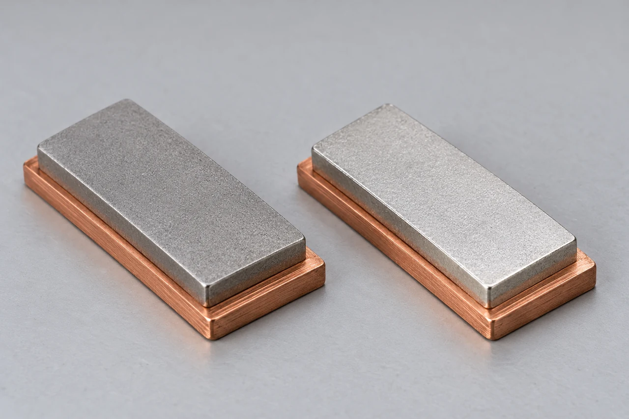
자동절체개폐기(ATS)와 차단기 접점은 전류를 안정적으로 전달하면서 투입 순간의 융착과 개폐 아크에 의한 손상을 견뎌야 합니다. 고정접점 Ag97/C3 은흑연과 가동접점 Ag60/W40 은텅스텐은 은흑연의 내융착 특성과 은텅스텐의 내아크 특성을 함께 활용하는 재료 조합입니다.
은은 전류와 열의 전달 경로를 만들고, 흑연은 접촉부의 강한 금속 결합을 억제하며, 텅스텐은 고온 개폐면의 내구성을 높이는 역할을 합니다. 재료의 성분과 조직에 접촉력·배면 접합·부하 조건을 맞추면 낮은 통전 손실과 안정된 개폐를 함께 설계할 수 있습니다.
은흑연의 내융착성
Ag97/C3는 은의 통전성과 흑연의 금속 결합 억제 작용을 활용합니다.
은텅스텐의 내아크성
Ag60/W40는 은의 전도성과 텅스텐상의 고온·변형 저항을 조합합니다.
접점쌍의 적용 조건
접촉력·배면 접합·부하·기구를 함께 맞춰 통전과 개폐 성능을 확보합니다.
01요구 성능과 접점 역할
ATS·차단기 접점의 요구 성능
ATS와 차단기의 전류 경로에는 도체를 연결하는 접점이 있습니다. 접점이 닫혀 있을 때에는 전압강하와 발열을 작게 유지하고, 전원을 투입하거나 끊을 때에는 순간적인 용융과 아크에 따른 손상을 견뎌야 합니다. 통전성·내융착성·내아크성은 서로 연결되지만, 각각 다른 상황에서 접점의 한계를 결정합니다.
통전성이 좋은 재료라도 투입 전류로 접촉부가 녹아 붙으면 정상적인 개방이 어려워집니다. 반대로 단단하고 침식에 강한 재료도 실제 맞닿는 면적이 작거나 표면막이 두꺼워지면 접촉저항이 커집니다. 접점 재질 선정은 전도율이나 경도 한 항목의 최고값을 고르는 작업보다, 장치가 요구하는 여러 성능의 균형을 정하는 작업에 가깝습니다.
통전·투입·차단의 서로 다른 부담
| 요구 성능 | 접점에서의 의미 | 설계와 평가의 초점 |
|---|---|---|
| 낮은 통전 손실 | 닫힌 접점의 전압강하와 열 발생 억제 | 접촉력·실접촉 면적·배면 접합·방열 경로 |
| 내융착성 | 용융 접촉부가 강하게 붙는 현상 억제 | 투입 전류·바운스·융착 분리력·개방 구동력 |
| 내아크·내침식성 | 개폐 아크에 의한 표면 소모와 형상 변화 억제 | 아크 지속시간·집중 위치·잔여 접점 높이 |
| 기계적 건전성 | 충격과 반복 하중에 대한 형태 유지 | 정렬·가장자리 지지·치핑·균열 |
| 수명 중 안정성 | 개폐 후에도 통전과 개방 기능 유지 | 저항 변화·온도상승·마모 후 접촉력 |
고정측 Ag97/C3 은흑연과 가동측 Ag60/W40 은텅스텐의 조합은 이러한 요구를 두 재료에 분담시킵니다. 은흑연은 금속끼리 강하게 붙는 현상을 억제하는 데 유리하고, 은텅스텐은 고융점 텅스텐상을 통해 아크와 기계적 부담에 대응합니다. 두 면이 만나는 계면의 저항과 분리 특성이 최종 성능을 좌우하므로 접점쌍 단위로 평가합니다.
정상 통전과 고장전류는 접점을 가열하는 시간과 방식도 다릅니다. 정상 전류에서는 발생한 열이 지지 도체와 단자를 통해 빠져나가는 능력이 중요합니다. 큰 순간 전류에서는 작은 접촉점에 에너지가 집중되고 전자기력이 접촉 상태를 바꿀 수 있습니다. 연속 통전의 온도상승과 순간 투입·단락 후의 상태를 구분해 살펴야 재료의 역할이 드러납니다.
장치 기능에 맞춘 접점 선정
ATS는 부하를 정상 전원과 대체 전원 사이에서 전환하는 장치입니다. 접촉기형이나 차단기 기반 구조에 따라 접점이 맡는 보호 기능이 달라집니다. 전원전환 접점은 부하 개폐와 정해진 단락 조건을 견디는 능력이 중요하고, 고장전류를 직접 끊는 차단기 접점은 개방 기구와 소호 구조까지 함께 작동해야 합니다.
따라서 재료 검토의 출발점은 사용 전류의 크기와 접점의 동작 역할입니다. 연속 통전 시간이 긴 장치, 돌입전류가 큰 부하, 잦은 부하 개폐, 긴 무동작 기간 뒤의 투입은 서로 다른 평가 항목을 요구합니다. 같은 재질을 사용해도 접촉력·접합·기구·부하가 달라지면 장치에서 확보되는 성능이 달라집니다.
고정접점과 가동접점의 역할
Ag97/C3 은흑연을 고정측에, Ag60/W40 은텅스텐을 가동측에 배치한 접점쌍에서는 두 재료가 서로 다른 기계적 역할로 맞닿습니다. 고정측은 지지 도체를 통해 위치와 열 전달 경로를 유지하고, 가동측은 구동 기구의 움직임을 받아 접촉과 분리를 수행합니다. 닫힌 상태에서는 같은 전류가 두 소재와 각각의 배면 접합부를 연속해서 통과합니다.
고정·가동이라는 구분은 움직임에 따른 이름이며 재료의 전기적 극성을 뜻하지 않습니다. 교류에서는 전류 방향이 주기적으로 바뀌고, 직류에서는 회로의 극성이 표면 반응과 재료 전이에 영향을 줍니다. 아크가 집중되는 위치도 접점의 움직임, 전류 경로와 소호 구조에 따라 달라지므로 양측의 손상을 대응시켜 확인합니다.
닫힘에서 안정 통전까지
가동접점이 처음 닿을 때에는 높이 차이와 기울기 때문에 일부 영역이 먼저 충돌합니다. 기구가 더 이동하면서 스프링이 변형되고 접촉력이 형성되면 실제 전류가 흐르는 접촉점이 변합니다. 최초 충돌 위치와 안정 통전 위치를 함께 보면 가장자리 손상과 국부 발열이 생기는 이유를 구분할 수 있습니다.
| 동작 단계 | 접점의 상태 | 중요한 기능 |
|---|---|---|
| 최초 접촉 | 국부 충돌과 작은 실접촉 영역 | 정렬과 충격 분산 |
| 접촉력 형성 | 스프링 변형과 접촉 영역 확대 | 안정된 힘·추가 이동 여유 |
| 안정 통전 | 양쪽 소재와 배면 접합으로 전류 전달 | 낮은 저항과 열 방출 |
| 개방 시작 | 마지막 접촉점에 전류 집중 | 융착 분리와 충분한 개방 구동 |
| 아크 소호·재투입 | 변화한 표면에서 다음 동작 수행 | 침식 후 접촉·절연·개방 성능 |
닫힘 직후 접점이 튀어 오르는 바운스는 짧은 개방과 재접촉을 반복시킵니다. 전류가 흐르는 상태에서는 이 과정이 작은 아크와 용융을 만들고, 재접촉 때 녹은 영역이 붙을 수 있습니다. 은흑연의 내융착 특성을 활용하려면 가동부 질량·닫힘 속도·감쇠·접촉 스프링을 함께 조정해 안정된 닫힘을 확보해야 합니다.
금속 접촉의 분리와 전류 차단
개방 초기에는 전류가 마지막으로 남은 작은 접촉점에 몰립니다. 그 지점이 가열·용융되면 두 면 사이에 액체 금속 다리가 형성되고, 다리가 끊어진 뒤에도 회로 에너지가 공급되면 아크가 이어집니다. 접점 간극을 만드는 기구와 아크를 소호하는 구조가 함께 필요한 이유입니다.
주접점과 아크접점을 따로 둔 장치는 접촉·분리 순서로 전류와 아크의 경로를 제어합니다. 주접점이 낮은 손실로 통전하고 아크접점이 개폐 말기의 부담을 맡도록 구성할 수 있습니다. 한 접점쌍이 통전과 개폐를 모두 담당하는 구조에서는 낮은 저항과 내아크성의 균형이 더욱 중요해집니다.
동작 검증에는 접점 전압·전류와 변위를 같은 시간축으로 기록하는 방법이 유용합니다. 최초 접촉 뒤 전압이 반복 상승하는 구간은 재개방을, 변위가 커진 뒤에도 전류가 남는 구간은 아크 지속을 살피는 단서입니다. 이렇게 기계적 움직임과 전기적 상태를 연결하면 재질 문제와 기구 문제를 더 정확히 구분할 수 있습니다.
고정·가동 판접점의 접촉 구조
가동접점이 떨어지면 금속 접촉 경로가 끊깁니다. 아크와 소호 거동은 접점 개방 동작과 장치의 차단 구조에 영향을 받습니다.
02은흑연·은텅스텐의 재질 특성
은흑연 Ag97/C3의 재질 특성
Ag97/C3 은흑연은 은 기지 안에 흑연상이 분산된 접점 복합재입니다. 은은 전류와 열이 이동하는 주된 경로를 만들고, 흑연은 접촉부에서 연속적인 금속 접합이 형성되는 것을 억제합니다. 은의 통전 특성과 흑연의 내융착 작용을 함께 활용해 큰 투입 전류나 반복 개폐에서 분리 성능이 중요한 접점에 사용됩니다.
융착은 국부적으로 녹은 금속이 두 접점 사이에서 다시 결합할 때 발생합니다. 흑연의 분산은 이런 금속 결합의 연속성을 끊어 분리에 필요한 힘을 줄이는 데 기여합니다. 따라서 은흑연의 장점은 단순히 표면이 미끄럽다는 설명보다, 작동 중 만들어지는 금속 접합의 형태를 바꾼다는 관점에서 이해하는 것이 정확합니다.
내융착성과 표면 소모의 관계
공기 중 아크의 고온에서는 흑연이 대기와 반응하며 표면 상태가 바뀝니다. 작동면이 은이 풍부한 상태로 변하는 현상은 낮은 접촉저항을 유지하는 거동과 연결되지만, 흑연의 소모와 조직 변화는 침식에도 영향을 줍니다. 은흑연은 내융착성이 중요한 곳에 강점이 있으며, 아크 부담이 큰 위치에서는 침식량과 잔여 높이를 함께 고려합니다.
| 재질 요소 | 접점 성능에 미치는 영향 | 제조·선정의 핵심 |
|---|---|---|
| 은 기지 | 전류와 열 전달 | 은의 연속 경로와 치밀화 |
| 흑연 분산 | 금속 접합의 연속성 억제 | 입자 크기·형태·응집 상태 |
| 흑연 배향 | 작동면의 침식·융착 거동 변화 | 압출 방향과 절단면의 관계 |
| 잔류 공극 | 국부 전류·응력 경로 변화 | 평균 밀도와 위치별 조직 |
| 접합 가능한 배면 | 지지 도체와의 안정된 결합 | 작동면 식별과 배면층 유지 |
같은 Ag97/C3라도 흑연이 고르게 분산된 조직과 큰 응집부를 가진 조직은 다르게 작동합니다. 흑연 덩어리나 큰 공극은 은의 전류 경로를 국부적으로 좁히고, 하중이 전달되는 방식도 바꿉니다. 평균 성분과 밀도에 더해 중심·가장자리의 조직을 확인하면 개폐 후 손상 편차의 원인을 좁힐 수 있습니다.
압출 방향과 작동면
압출과 압연은 흑연을 가공 방향으로 정렬시킬 수 있습니다. 이때 판접점을 어느 방향으로 절단하는지에 따라 작동면에 드러나는 흑연의 형상이 달라집니다. 조직 방향은 내침식성과 내융착성에 서로 다른 영향을 줄 수 있으므로, 재료 선택과 함께 최종 접촉면의 방향을 지정하는 것이 중요합니다.
은흑연의 기계적 취급에서는 가장자리와 배면 지지 상태가 중요합니다. 더 단단한 상대 접점이 기울어진 상태로 충돌하면 한쪽 모서리에 하중이 몰려 치핑이 시작될 수 있습니다. 모서리가 떨어져 나가면 다음 접촉의 위치와 전류 분포도 바뀌므로, 면 정렬과 접합 지지를 확보하는 것이 재질의 장점을 유지하는 방법입니다.
은흑연 선정에서 확인할 결과는 융착 분리력, 반복 개폐 뒤 접촉저항, 표면 소모와 가장자리 건전성입니다. 분리가 쉬워지는 변화와 침식이 줄어드는 변화가 항상 같은 방향으로 움직이지는 않습니다. 부하의 투입 특성과 개폐 빈도에 맞춰 두 성능의 우선순위를 정하면 Ag97/C3의 적용 목적이 명확해집니다.
은텅스텐 Ag60/W40의 재질 특성
Ag60/W40 은텅스텐은 은의 전도성과 고융점 텅스텐의 내구 특성을 조합한 복합 접점 재료입니다. 은은 전류와 열의 전달을 맡고, 텅스텐상은 아크에 노출되는 표면의 침식과 기계적 변형을 억제하는 데 기여합니다. 가동측 S60A2의 조성은 Ag60/W40로 구분하며, 은과 텅스텐의 분포가 실제 개폐 성능에 영향을 줍니다.
텅스텐은 은보다 훨씬 높은 온도에서 용융하므로 고온 개폐면을 지지하는 역할을 합니다. 다만 접점 안에서 전류가 이동하는 길은 은의 연결 상태와 공극 분포에도 좌우됩니다. 은 함량을 높이면 전류 전달에 유리해지는 반면 경도는 낮아지는 경향이 있어, 조성은 내구성과 통전성을 함께 조정하는 설계 변수입니다.
내아크성과 접촉저항의 균형
은텅스텐의 경한 표면은 국부적인 눌림과 소성변형을 억제하지만, 같은 접촉력에서 실제 맞닿는 미세 영역이 작아질 수 있습니다. 전류가 작은 영역에 모이면 집중저항이 증가합니다. 여기에 개폐 후 생성된 산화물 등의 표면막이 더해질 수 있으므로, 소재 내부 전도율과 두 접점 사이의 계면저항을 나누어 봅니다.
| 특성 | 은텅스텐의 역할 | 적용에서 연결할 항목 |
|---|---|---|
| 텅스텐 분산상 | 고온 표면과 기계적 형상 유지에 기여 | 아크 침식·충격·균열 |
| 은의 연결 경로 | 전류·열 전달 | 전도율·공극·은 분포 |
| 경한 접촉면 | 변형 억제와 실접촉 면적의 절충 | 접촉력·형상·계면저항 |
| 개폐 후 표면 변화 | 은 소실·W-rich 영역·표면막 형성 | 시험 후 저항과 온도상승 |
| Ag60/W40 조성 | 은 60·텅스텐 40의 성분 구분 | 공급 등급·성분표·제조 상태 |
조직에서는 은이 넓게 몰린 영역, 텅스텐의 응집, 공극과 상 경계의 연결 상태를 살핍니다. 은과 텅스텐이 고르게 분포하면 국부적인 전류·열 부담을 줄이는 데 유리합니다. 반면 불균일한 영역은 동일한 평균 밀도에서도 다른 침식과 균열 양상을 만들 수 있어, 물성표와 단면 조직을 함께 관리합니다.
개폐 후 표면과 잔여 성능
반복 아크에 노출되면 은과 텅스텐이 같은 속도로 소모되지 않습니다. 은이 선택적으로 빠져나간 표면에는 텅스텐이 상대적으로 많은 영역과 공극이 남을 수 있습니다. 새 접점의 매끈한 표면과 달리 이 상태에서는 접촉점과 열 전달 경로가 바뀌므로, 수명 중의 저항 변화가 재료 평가의 중요한 지표가 됩니다.
아크가 머무는 위치 역시 소재의 성능을 크게 좌우합니다. 넓은 작동면을 쓰더라도 아크가 한쪽에 집중되면 그 부위의 잔여 두께가 먼저 줄고 국부 균열이 생길 수 있습니다. 소호 경로와 접점 형상을 함께 검토하고, 전체 질량 감소와 가장 깊은 침식부를 구분하면 실제로 필요한 내구 여유를 판단하기 쉽습니다.
은텅스텐은 아크와 기계적 부담이 있는 접점에 적합한 재료군이며, Ag60/W40의 적용에서는 상대 Ag97/C3 면과의 접촉 상태를 함께 맞춥니다. 접촉력이 부족하면 경한 면의 장점을 충분히 활용하기 어렵고, 충격이 한쪽에 몰리면 상대 은흑연의 손상이 커질 수 있습니다. 재질의 내구성과 접점쌍의 안정된 동작을 함께 확보하는 것이 선정의 핵심입니다.
은흑연·은텅스텐의 분산 조직
은 기지에 흑연이 분산된 구조입니다. 흑연의 분포·형상·배향과 치밀화 상태를 조성과 함께 확인합니다.
03재질 비교와 판접점 제조
은흑연·은텅스텐의 조합과 비교
은흑연과 은텅스텐은 모두 은을 포함하지만, 흑연과 텅스텐이 맡는 기능은 다릅니다. 은흑연은 접촉부의 금속 결합을 억제해 내융착성을 확보하는 쪽에 강점이 있고, 은텅스텐은 고온과 기계적 부담에서 형상을 유지하는 쪽에 강점이 있습니다. 재료 비교는 은 함량의 크기보다 이 분산상이 바꾸는 작동 특성을 중심으로 이루어집니다.
Ag97/C3를 고정측에, Ag60/W40를 가동측에 배치한 접점쌍에서는 은흑연의 분리 특성과 은텅스텐의 내구 특성을 한 계면에서 활용합니다. 양측을 같은 단단한 재질로 구성할 때와 비교해 접촉면의 순응성과 융착 거동을 조정할 수 있습니다. 동시에 상대적으로 소모되기 쉬운 면의 잔여 높이와 가장자리 상태를 관리해 두 재료의 수명을 맞춥니다.
재질별 강점과 설계 조건
| 비교 항목 | Ag97/C3 은흑연 | Ag60/W40 은텅스텐 |
|---|---|---|
| 구조 | 은 기지와 분산 흑연 | 은과 금속 텅스텐의 복합 조직 |
| 주요 강점 | 금속 결합 억제에 따른 내융착성 | 고융점 상에 의한 내아크·기계적 내구성 |
| 통전 거동 | 은 경로와 개폐 후 표면 상태가 중요 | 은 경로·실접촉 면적·표면막이 중요 |
| 주요 절충 | 내융착성에 더해 침식·치핑 관리 | 내구성에 더해 계면저항·상대면 충격 관리 |
| 조직 관리 | 흑연 분산·배향·공극 | 은 분포·텅스텐 분산·공극 |
| 접점쌍 평가 | 분리력·소모량·모서리 상태 | 저항 변화·침식 깊이·균열 |
접점쌍에 동일한 전류가 흘러도 두 면의 손상이 같지는 않습니다. 전류 방향, 아크의 위치, 접촉·분리 운동에 따라 한쪽에서 소모된 물질이 상대편에 쌓이기도 합니다. 한쪽의 돌기와 상대편의 크레이터를 대응시켜 보면 재료 전이가 다음 접촉 위치를 어떻게 바꾸는지 알 수 있습니다. 따라서 한 면의 외관보다 두 면이 계속 맞물려 작동하는 상태가 중요합니다.
사용 조건에 따른 성능의 우선순위
투입 전류가 큰 부하에서는 바운스 중 용융과 재접촉이 내융착성의 부담을 키웁니다. 개폐가 잦고 아크 지속시간이 긴 조건에서는 표면 침식과 잔여 형상이 수명을 제한하기 쉽습니다. 연속 통전 비중이 큰 장치에서는 접촉저항과 접합부의 열 전달이 중요해집니다. 부하의 특성에 따라 같은 접점쌍에서도 우선 평가할 지표가 달라집니다.
재료의 변경 효과를 판단할 때에는 전기적 내구와 기계적 내구를 나눠 봅니다. 무부하 반복 작동에서 생기는 치핑은 충격·정렬·지지 상태와 연결되고, 부하 개폐에서 추가되는 침식과 전이는 전류·아크의 영향을 반영합니다. 이 차이를 이용하면 재질 변경이 필요한지, 접촉력과 기구를 조정해야 하는지 판단하기 쉬워집니다.
조합의 최적화는 내융착성 한 항목을 최대화하는 방식으로 끝나지 않습니다. 필요한 개방력을 유지하면서 저항·온도상승·침식·파손이 함께 허용 범위 안에 들어와야 합니다. 특히 교체 시점은 접점이 얼마나 남았는지뿐 아니라 마모 후 접촉력이 유지되는지, 다음 개방이 안정적으로 이루어지는지와 연결됩니다.
판접점의 소재 제조와 가공
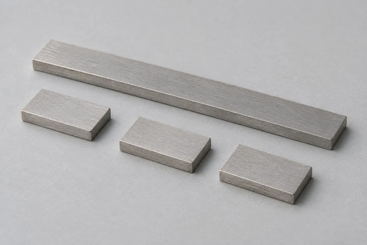
AgC의 대표적인 제조 흐름은 은·흑연 분말 준비, 혼합, 압축 성형, 소결과 후속 치밀화입니다. 제품에 따라 압출·압연 또는 재압축을 조합하고 필요한 형상으로 절단·가공합니다. 처음의 혼합 상태는 이후 분산의 출발점이지만, 최종 조직은 가공 방향과 열 이력까지 거친 결과입니다.
AgW에는 혼합 분말을 성형·소결·재압축하는 경로와, 다공성 텅스텐 성형체에 용융 은을 침투시키는 경로가 사용됩니다. 침투 경로에서는 텅스텐 골격의 공극 연결성과 은의 충전이 중요하고, 혼합 분말 경로에서는 분산·소결·잔류 공극을 관리해야 합니다. 어느 경로든 공칭 조성만 같다고 공정 결과가 같아지는 것은 아닙니다.
제조 단계와 완성품 특성의 연결
| 단계 | 관리 초점 | 후속 공정에서 드러나는 영향 |
|---|---|---|
| 분말 준비·혼합 | 입도·순도·응집·배합·혼합 균일성 | 분산상과 국부적인 조성 편차 |
| 압축·소결 | 성형 균일성·치밀화·오염·잔류 공극 | 밀도·강도·전도 경로 |
| 압출·압연·재압축 | 가공 방향·균열·치수·조직 변화 | 작동면 배향·절단 방향·기계적 거동 |
| 절단·면 가공 | 기준면·높이·가장자리 손상·표면 | 접촉 위치·하중 분포·배면 밀착 |
| 세정·포장 | 잔류물·이물·면 보호·로트 식별 | 접합 품질·초기 저항·추적성 |
치밀화와 조직 균일성
혼합 분말 경로에서는 압축과 소결로 입자 사이의 결합을 만들고 재압축 등으로 남은 공극을 줄입니다. 침투 경로에서는 연결된 공극으로 은이 들어갈 수 있어야 하며, 막힌 영역이나 불균일한 예비성형체는 충전 편차를 만들 수 있습니다. 최종 밀도가 비슷해도 은의 분포가 다른 이유가 제조 경로에 있습니다.
판재의 어느 위치에서 접점을 채취해도 기능이 일정하려면 길이 방향과 단면 위치에 따른 조직 편차를 줄여야 합니다. 소재의 대표 위치에서 같은 절단 방향으로 공극과 분산을 비교하면, 밀도만으로 드러나지 않는 국부적인 불균일을 찾을 수 있습니다. 균일한 조직은 접점별 저항과 침식 편차를 줄이는 제조 기반입니다.
치밀화는 공극을 줄이고 전류와 하중의 전달 경로를 확보하는 과정입니다. 큰 공극이 작동면 가까이에 있으면 표면이 소모되면서 드러나 접촉 영역을 바꿀 수 있고, 배면 가까이에 있으면 접합과 지지에 영향을 줄 수 있습니다. 그래서 공극은 전체량뿐 아니라 크기와 위치를 함께 관리합니다.
후속 가공에서는 흑연 배향과 텅스텐상의 분포에 맞춰 절단면과 모서리를 관리합니다. 과도한 연마로 연한 금속이 표면을 덮으면 원래의 분산 조직이 드러나는 상태가 바뀌고, 배면 접합층을 많이 깎으면 브레이징 적합성이 낮아질 수 있습니다. 작동면의 마감, 모서리 손상과 접합층의 잔여량을 함께 정해 소재 기능을 보존합니다.
완성 판접점은 절단 흔적과 잔류물을 제거한 뒤 작동면과 접합면이 손상되지 않도록 취급합니다. 이물은 초기 접촉저항을 흔들고 브레이징의 젖음을 방해할 수 있습니다. 소재 방향과 로트 식별을 가공 이후에도 유지하면 같은 외형의 접점이 서로 다른 방향이나 배면 상태로 조립되는 것을 방지할 수 있습니다.
04접합과 접촉 구조
배면층과 브레이징 접합
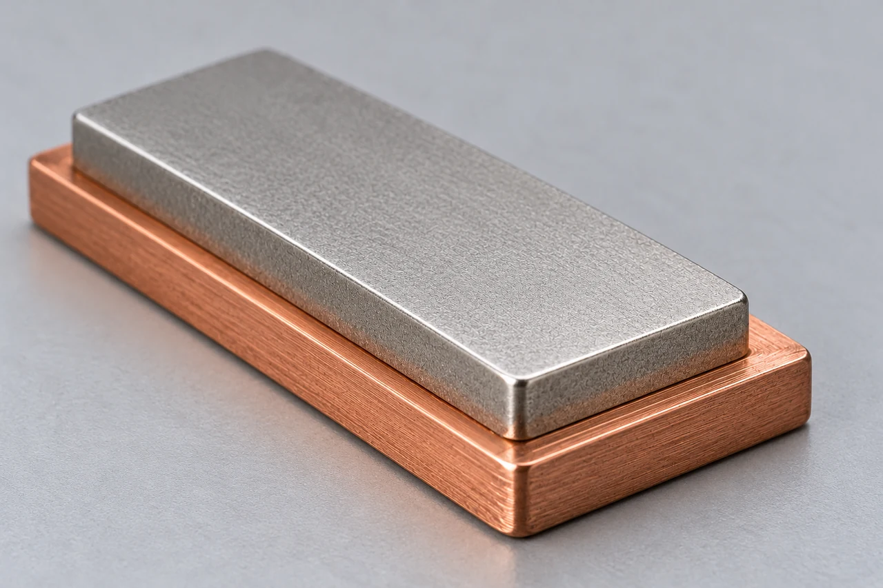
판접점은 작동면에서 상대 접점과 만나고, 배면에서는 구리 등의 지지 도체와 결합합니다. 배면 접합은 전류를 전달하고 열을 배출하며 닫힘 충격을 받쳐 주는 구조입니다. 접점 재질이 우수해도 이 연결부의 연속성이 나쁘면 국부 발열과 응력이 커져 재질의 장점을 충분히 활용하기 어렵습니다.
AgC의 흑연 함유면은 통상적인 브레이징 용가재가 안정적으로 젖기 어렵습니다. 따라서 흑연이 없는 은 측을 만들거나 별도의 접합 가능한 배면층을 마련해 지지 도체와 연결합니다. AgW에도 접합 적합성을 높이는 배면 구성을 사용할 수 있습니다. 작동면의 복합 조직과 접합면의 젖음 특성을 각각 확보하는 방식입니다.
배면층과 브레이징층의 역할
| 구성·항목 | 담당 기능 | 확인할 내용 |
|---|---|---|
| AgC·AgW 접점 본체 | 상대면과 전기적·기계적으로 접촉 | 작동면·조성·조직·잔여 두께 |
| 접합 가능한 배면층 | 본체와 접합 공정의 적합성 확보 | 재료·연속성·두께·가공 후 잔여량 |
| 브레이징 용가재층 | 접점과 지지 도체 사이의 결합 형성 | 적합한 용가재·간극·젖음·공극 |
| 지지 도체 | 전류·열 전달과 기계적 지지 | 재질·표면·평면도·열에 따른 변형 |
| 접합 후 조립품 | 전체 전류·열·하중 경로 유지 | 접합 강도·국부 저항·치수·외관 |
브레이징 간극과 열팽창
브레이징 용가재는 젖음이 가능한 두 면 사이의 좁은 간극으로 모세관 작용에 의해 퍼집니다. 간극이 지나치게 닫히면 흐름이 막히고, 너무 넓으면 충전과 접합부 성질이 달라집니다. 중요한 간극은 가열된 상태의 값입니다. 접점·지지 도체·지그의 열팽창 차이까지 고려해 고온에서의 자세와 간극을 검토합니다.
냉각 뒤에는 접합된 서로 다른 재료가 함께 수축하면서 변형과 잔류 응력이 생길 수 있습니다. 그래서 접합 강도만 보지 않고 작동면 기울기와 접촉 높이를 다시 측정합니다. 단면 검사도 중앙 한 곳에 그치지 않고 가장자리·가압 위치를 포함하면 미충전, 층 불연속과 국부 반응 차이를 더 잘 구분할 수 있습니다.
접합 공정에서는 표면 산화물과 잔류물을 제거하고, 용가재·배면층·지지 도체의 조합에 맞춰 가열과 가압을 정합니다. 가열이 한쪽에 몰리면 용가재의 흐름과 반응이 달라지고, 가압이 과도하면 필요한 간극이 닫히거나 용가재가 밀려날 수 있습니다. 균일한 열 이력과 안정된 위치 고정이 접합층의 연속성과 형상 재현성을 높입니다.
공극은 면적 비율뿐 아니라 위치도 중요합니다. 가장자리 또는 실제 하중이 집중되는 곳에 접합이 부족하면 국부 응력과 열 흐름이 달라집니다. 반대로 외관상 용가재가 둘러 보인다고 내부 전체가 접합됐다고 판단할 수 없습니다. 개발 단계의 단면·강도·전기 검사를 연결해 양산의 비파괴 검사와 공정 감시 범위를 정합니다.
용가재층은 단순히 두 부품 사이에 남는 금속 막이 아닙니다. 가열 중에는 모재와 표면층의 성분이 확산·반응하고, 냉각하면서 최종 접합 조직이 형성됩니다. 용가재 이름이 같아도 배면 형상·도금 상태·가압·가열 시간이 달라지면 결과가 달라질 수 있어, 재료 조합과 접합 조건을 함께 관리합니다.
판접점과 지지 도체의 접합 구조
판접점, 접합용 하부층, 브레이징 접합부와 지지 도체의 위치를 구분합니다. 접합용 하부층은 소재와 접합 공법에 맞춰 선정합니다.
접촉 형상과 기구 설계
판접점의 두께는 조립 높이와 접촉 시점에 연결됩니다. 접합층과 지지 도체까지 포함한 높이 차이는 먼저 닿는 위치와 스프링 압축량을 바꿉니다. 소재 상태의 두께를 잘 맞춰도 접합 후 기울어지면 실제 접촉 조건은 달라집니다. 완성 조립품 기준의 높이·자세·힘을 함께 확인해야 합니다.
작동면의 평면도와 곡률은 하중이 퍼지는 방식과 최초 접촉 위치를 결정합니다. 회전하는 가동부는 접촉 과정에서 자세가 변하고, 직선으로 움직이는 구조도 조립 기울기의 영향을 받습니다. 상대면과 이동 경로에 맞는 형상을 정하면 편접촉을 줄이고 은흑연의 가장자리와 은텅스텐의 국부 접촉부에 집중되는 부담을 완화할 수 있습니다.
치수와 기능을 연결하는 도면 항목
| 도면 항목 | 기능과의 관계 | 권장 확인 단계 |
|---|---|---|
| 전체 조립 높이 | 최초 접촉과 추가 이동량 | 접합 후·최종 조립 후 |
| 작동면 형상 | 접촉 위치·하중 분포 | 소재 가공 후와 접합 후 |
| 작동면의 기울기 | 편접촉·가장자리 충돌 | 지지 도체 기준 자세 검사 |
| 모서리·치핑 | 파손 시작점과 손상 확대 | 입고·가공·접합·작동 시험 후 |
| 배면 지지 면적 | 충격 하중과 열 전달 | 접합부 평가와 기구 검토 |
| 접촉력·추가 이동량 | 저항·바운스·마모 후 여유 | 완성품 힘-변위 검사 |
접촉 높이와 접촉력
접촉 뒤에는 작은 높이 편차도 스프링 변형량과 접촉력을 바꿉니다. 같은 높이 편차라도 접점 위치에서의 기구 강성이 크면 힘의 편차가 커집니다. 접점과 접합층을 포함한 조립 높이 공차를 접촉력 허용범위에 맞추면 제품 간 저항과 충격의 편차를 줄이는 데 도움이 됩니다.
마모가 진행되면 기구가 더 이동한 뒤에야 접촉할 수 있어 추가 압입 여유와 힘이 줄 수 있습니다. 반대로 처음부터 높이가 과도하면 큰 충격이나 힘을 만들 수 있습니다. 유효 강성이 일정하지 않은 회전·스냅 기구는 실제 힘-변위 곡선으로 판단하며, 새 상태와 수명 후 상태를 같은 곡선 위에서 비교합니다.
은흑연에 생긴 가장자리 치핑은 다음 동작의 하중과 전류 분포를 바꿉니다. 접촉면이 줄어 남은 영역에 힘이 몰리면 추가 파손과 발열이 이어질 수 있습니다. 더 단단한 은텅스텐 가동면의 충격을 안정적으로 받아 주도록 두 면의 자세와 배면 지지 면적을 맞추는 것이 접점쌍의 기계적 내구에 중요합니다.
충격을 줄이려면 재료 강도만 높이기보다 기구의 닫힘 속도, 감쇠, 지지 강성, 접촉 순서를 함께 검토합니다. 반대로 충격을 줄이는 변경이 개방 성능이나 접촉력 형성을 해치지 않는지도 확인해야 합니다. 닫힘·열림 전체의 힘과 변위 이력을 기록하면 재질 변경과 기구 변경의 효과를 구분하기 쉬워집니다.
반복 시험 뒤에는 접점 두께만 측정하지 말고, 실제 맞닿는 위치와 사용 가능한 추가 이동량도 확인합니다. 소재가 남아 있어도 접촉력이 줄거나 기구가 한계 위치에 도달하면 기능을 잃을 수 있습니다. 잔여 두께와 기구 여유를 함께 관리하는 것이 판접점 수명 설계의 핵심입니다.
05발열과 개폐 손상
접촉저항과 온도상승
닫힌 접점의 저항은 은의 전도율만으로 결정되지 않습니다. 두 면이 실제로 닿는 미세 영역에 전류가 모이면서 집중저항이 생기고, 표면막과 소재 내부·배면 접합·지지 도체의 저항이 더해집니다. Ag97/C3와 Ag60/W40를 조합할 때에는 두 소재의 통전 경로가 접촉 계면과 접합부를 거쳐 이어지도록 설계해야 합니다.
접촉력이 줄면 실제 금속 접촉 영역이 작아져 국부 전류밀도와 발열이 커질 수 있습니다. 마모로 추가 이동량이 줄거나 스프링과 지지부의 상태가 바뀌면 이러한 변화가 수명 중에 나타납니다. 반대로 접촉력만 크게 높이면 구동 부담과 충격 조건도 달라지므로, 저항과 기구 동작을 함께 만족하는 힘의 범위를 정합니다.
전류 경로별 손실
| 측정 구간 | 포함되는 항목 | 해석 목적 |
|---|---|---|
| 개별 소재 시편 | 소재 내부의 저항 | 전도율·치밀화·방향성 비교 |
| 접점쌍 가까운 두 지점 | 계면과 일부 접점 본체 | 접촉력·표면 상태에 따른 변화 |
| 접점-지지 도체의 양측 | 배면 접합부와 인접 구간 | 접합 품질과 국부 손실 평가 |
| 조립품 단자 사이 | 도체·접합·계면의 합 | 실제 전압강하와 전체 성능 |
| 온도상승 시험 | 전기 손실과 방열 조건의 결합 | 설치 조건에서의 열적 적합성 |
표면 변화와 저항의 안정성
표면막의 영향을 확인하려면 저전압·저전류로 접촉부를 변화시키지 않는 드라이 회로 측정을 먼저 고려합니다. 큰 시험 전류가 접촉점을 가열하거나 막을 파괴하면 처음보다 낮은 저항이 측정될 수 있기 때문입니다. 다만 저신호 측정은 표면 상태의 진단이고, 정격 통전의 전압강하·온도상승 시험은 별도의 검증입니다.
저항은 한 번의 평균값보다 반복 측정의 분포가 유용합니다. 같은 시편을 같은 힘으로 다시 닫았을 때 값이 크게 달라지면 접촉 위치와 표면 상태의 변동을 의심할 수 있습니다. 온도 안정화 전후와 작동 횟수별 결과를 같은 조건으로 비교하면 일시적인 표면 변화와 지속적인 열·기계 문제를 구분하기 쉬워집니다.
4단자법은 전류를 흘리는 선과 전압을 읽는 선을 분리해 리드선의 영향을 줄입니다. 그러나 검출점을 어디에 두는지에 따라 포함되는 저항은 여전히 달라집니다. 작은 신호에서는 열기전력과 안정화 시간도 확인하고, 필요한 경우 계측 절차에 맞춘 전류 반전으로 영향을 평가합니다. 측정값과 함께 배선·검출 위치를 남겨야 재현할 수 있습니다.
발열 전력의 기본 관계는 P = I²R입니다. 같은 저항에서 전류가 두 배가 되면 손실은 네 배가 됩니다. 그러나 이 관계만으로 온도상승을 계산할 수는 없습니다. 접점과 접합부에서 생긴 열이 도체·단자·주변 공기로 얼마나 빠르게 이동하는지, 주위온도와 장착 조건이 어떤지를 함께 알아야 합니다.
같은 전기 손실이라도 지지 도체의 단면과 길이, 접합 상태, 단자 체결과 외함 조건이 다르면 온도상승이 달라집니다. 접점 가까이에 생긴 열이 빠져나갈 경로가 좁으면 그 부위의 온도가 높아집니다. 실제 장착 조건의 온도와 구간별 전압강하를 연결하면 재질을 바꿔야 할 문제인지, 접촉력이나 방열 경로를 개선할 문제인지 판단할 수 있습니다.
융착·침식·파손 평가
접점 손상은 개방을 방해하는 융착, 재료를 소모시키는 침식, 상대면으로 이동하는 재료 전이, 충격에 따른 치핑과 균열로 나눌 수 있습니다. 각 손상은 접촉저항과 다음 개폐에 서로 다른 영향을 줍니다. Ag97/C3와 Ag60/W40의 수명을 평가할 때에는 손상 종류와 장치 기능의 변화를 함께 연결합니다.
융착이 발생하면 필요한 분리력이 커져 개방 시간이 늘어나거나 개방에 실패할 수 있습니다. 투입 전류가 큰 순간의 바운스, 작은 실접촉 영역과 용융부의 재접촉이 주요 검토 대상입니다. 내융착 재질을 적용하는 동시에 투입 파형과 개방 구동력을 연결하면 재료의 효과와 기구의 여유를 구분할 수 있습니다.
손상 형태와 성능의 연결
| 손상 형태 | 작동에 미치는 영향 | 주요 평가 지표 |
|---|---|---|
| 융착 | 개방 지연·분리력 증가·개방 실패 | 융착 빈도·분리력·접점 전압/전류 파형 |
| 국부 침식 | 접촉 높이와 마모 여유 감소 | 최대 깊이·체적 감소·잔여 높이 |
| 재료 전이 | 돌기와 크레이터로 접촉 위치 이동 | 양측 대응 형상·질량 변화·전류 방향 |
| 치핑·균열 | 남은 면의 하중 집중과 파손 확대 | 발생 위치·깊이·배면 지지·기계 작동 이력 |
| 표면·접합 저항 상승 | 국부 발열과 통전 손실 증가 | 구간별 전압강하·온도·접촉력 |
침식은 전체 질량 감소와 가장 깊은 손상부를 나누어 봅니다. 아크가 한 점에 머무르면 질량 감소가 크지 않아도 국부적으로 깊은 크레이터가 생길 수 있습니다. 반면 재료가 상대면으로 이동하면 한쪽은 줄고 다른 쪽은 늘어 전체 질량만으로는 형상 변화를 설명하기 어렵습니다. 양측 표면의 높이 변화와 잔여 두께가 다음 접촉에 직접 연결됩니다.
아크 전압·전류·지속시간은 함께 접점의 열적 부담을 결정합니다. 같은 피크 전류라도 아크가 오래 지속되면 더 큰 에너지가 전달될 수 있습니다. 에너지가 집중된 위치를 표면 손상과 연결하면 소재와 소호 구조가 침식에 미치는 영향을 함께 이해할 수 있습니다.
표면 손상과 내부 결함의 구분
은텅스텐 표면의 공극과 텅스텐이 많은 영역은 은의 선택적 소실과 연결될 수 있고, 은흑연 가장자리의 탈락은 편접촉과 충격에 연결될 수 있습니다. 접합부 주변의 발열은 배면 연속성과 전류 경로를 살필 단서입니다. 손상 위치를 접촉 흔적·힘·저항 이력과 맞춰 보면 재료 조직, 기구 또는 접합 중 어느 경로에서 문제가 시작됐는지 좁힐 수 있습니다.
고정·가동측은 세정 전 같은 기준 방향으로 촬영하고, 손상되지 않은 영역을 기준으로 형상을 맞춰 비교합니다. 이후 필요한 위치의 단면을 관찰하면 공극·균열·층 분리의 깊이를 확인할 수 있습니다. 표면 성분 분석은 변화한 재료를 추적하는 데 유용하며, 전압강하와 온도 결과를 함께 놓으면 단순 변색과 기능을 제한하는 손상을 구분하기 쉽습니다.
수명 판단에서는 접점이 다시 열리는지, 닫힌 뒤 요구되는 전류를 전달하는지, 마모 후에도 접촉력이 남는지를 함께 평가합니다. 침식량이 작아도 표면 돌기로 접촉이 불안정해질 수 있고, 소재가 충분히 남아도 기구의 추가 이동 여유가 소진될 수 있습니다. 재료의 잔여량과 조립품의 잔여 기능을 함께 보는 것이 실제 교체 기준을 만드는 방법입니다.
06적용 선정과 품질관리
부하 조건별 접점 선정
ATS·차단기 접점의 적용은 장치가 오랫동안 전류를 전달하는지, 자주 부하를 전환하는지, 고장전류를 직접 차단하는지에 따라 달라집니다. 은흑연과 은텅스텐의 조합은 내융착성과 내아크성을 함께 다루는 선택지이며, 사용 조건에 맞는 접촉력과 열·아크 경로가 갖춰질 때 장점을 활용할 수 있습니다.
연속 통전 시간이 긴 전환 장치에서는 초기 저항뿐 아니라 반복 동작과 보관 뒤의 저항 안정성이 중요합니다. 은을 통한 전류 전달, 실제 접촉 면적과 지지 도체의 방열을 함께 확보해야 온도상승을 낮출 수 있습니다. 개폐 횟수가 적더라도 필요할 때 안정적으로 투입·개방할 수 있도록 표면 상태와 기구 기능을 함께 관리합니다.
사용 조건과 재질 특성의 연결
| 사용 조건 | 접점의 주요 부담 | 재질·구조에서 중점적으로 볼 항목 |
|---|---|---|
| 장시간 연속 통전 | 접촉부·접합부의 누적 발열 | 안정된 저항·접촉력·방열 경로 |
| 큰 돌입전류의 투입 | 바운스 중 용융과 융착 | AgC 내융착성·닫힘 안정성·분리 여유 |
| 잦은 부하 개폐 | 반복 아크와 표면 형상 변화 | AgW 내아크성·양측 침식·마모 후 높이 |
| 고장전류 통과 | 순간 발열과 전자기력 | 접촉 유지·내융착·도체와 보호장치의 협조 |
| 고장전류 직접 차단 | 개방 중 아크와 절연 회복 | 기구·소호부·접점 재질의 통합 성능 |
| 장기 대기·환경 노출 | 표면막과 접촉 상태 변화 | 환경 후 저항·투입·개방 성능 |
전동기·변압기·용량성 부하는 투입 순간의 전류가 정상 통전 전류와 다를 수 있습니다. 이때 접점이 바운스하면 작은 접촉 영역에 큰 전류가 반복해서 흐르고, 국부 용융과 재접촉이 융착 부담을 키웁니다. 정상 전류값만 맞추기보다 실제 투입 파형과 기구의 닫힘 상태를 기준으로 은흑연의 내융착 기능을 평가합니다.
개방에서는 부하의 에너지가 아크의 지속에 영향을 줍니다. 교류의 전류 영점, 직류의 극성과 회로 시정수, 부하의 유도성에 따라 차단 과정이 달라집니다. 은텅스텐의 내아크 특성을 적용할 때에도 해당 회로에서 아크가 얼마나 지속되고 어느 면에 집중되는지 연결해야 접점 형상과 잔여 두께를 정할 수 있습니다.
전환 기능과 보호 기능의 조합
고장전류를 외부 보호장치가 제거하는 ATS에서는 그 장치가 동작할 때까지 접점과 도체가 견뎌야 합니다. 보호장치의 동작 시간과 통과 전류는 접점에 전달되는 열적·기계적 부담을 바꿉니다. 반면 차단기 기반 구성에서 해당 접점이 직접 차단을 수행하면 개방 속도, 아크 이동과 절연 회복까지 접점 선정에 포함됩니다.
전압 정격은 접점 재료만으로 정해지지 않습니다. 접점 간극과 절연 구조, 개방 기구와 소호 성능이 함께 전압에 대응합니다. 전류 용량 역시 접점 면적·힘·도체·접합·열 방출의 결과입니다. Ag97/C3와 Ag60/W40의 성질은 이러한 장치 설계 안에서 활용되는 재료 특성이며, 제품 정격은 조립된 장치의 성능으로 결정됩니다.
개발 단계에서는 통전 손실, 융착 분리, 침식과 기계 손상 중 수명을 먼저 제한하는 항목을 찾습니다. 그 항목에 맞춰 소재 조직·접촉력·접합 또는 소호 경로를 개선하고, 나머지 성능이 유지되는지 함께 비교합니다. 이런 순서로 접근하면 재질 변경의 목적이 분명해지고 필요한 성능을 갖춘 접점쌍을 선정하기 쉬워집니다.
도면 사양과 품질관리
접점 도면은 소재의 장점을 완성 조립품에서 재현하기 위한 기준입니다. Ag97/C3 고정측과 Ag60/W40 가동측을 식별하고, 작동면·배면층·소재 방향·조립 기준면을 연결합니다. 가공과 접합 뒤에도 의도한 면이 접촉하고 필요한 높이와 자세가 유지돼야 같은 재료에서 일관된 통전·개폐 성능을 얻을 수 있습니다.
재료 사양에는 성분과 조성 단위, 공급 등급, 제조 상태와 주요 물성의 허용 범위를 함께 표시합니다. S60A2 등 공급 등급은 Ag60/W40의 성분 사양과 연결해 관리합니다. 명칭이 같아도 조직 방향이나 배면 구성이 바뀌면 가공·접합·작동 조건이 달라지므로 재료와 접합 구조를 하나의 구매 사양으로 묶는 것이 효과적입니다.
소재·형상·접합의 관리 항목
| 구분 | 필요한 정보 | 기술적 목적 |
|---|---|---|
| 소재 정의 | 조성·단위·공급 등급·첨가제·제조 상태 | 동일 이름 아래 다른 소재의 혼입 방지 |
| 판접점 도면 | 기준면·높이·작동면·방향·모서리·배면 | 접촉과 접합 기능의 재현 |
| 접합 사양 | 지지 도체·배면층·용가재·공정·검사 | 전류·열·하중 경로 확보 |
| 장치 조건 | 정격·AC/DC·부하·접촉력·기구·소호 구조 | 재료 평가 조건과 실제 사용 연결 |
| 검증 계획 | 측정점·시험 순서·표본·중간 검사·합격 기준 | 비교 가능성과 판정 일관성 |
| 변경관리 | 소재·공급처·분말·공정·접합·기구 변경 | 영향 평가와 필요한 재검증 |
설계 변경과 성능 재검증
흑연 배향을 바꾸면 내융착·침식 비교를, 배면층이나 용가재를 바꾸면 접합 조직·강도·저항을 우선 검토합니다. 접점 높이나 지지 도체 형상을 바꾸면 힘·바운스·온도상승까지 연결됩니다. 이처럼 변경 원인에서 영향을 받는 경로를 따라 시험을 정하면 불필요한 반복과 중요한 누락을 함께 줄일 수 있습니다.
승인 기준에는 완성품의 외관과 치수뿐 아니라 소재 조직, 접합 상태, 초기 접촉력과 저항을 연결합니다. 생산품을 같은 방법으로 비교하면 외형이 비슷한 부품에서도 소재 방향, 접합 또는 기구의 변화를 찾을 수 있습니다. 로트 추적은 성분 성적서에서 끝나지 않고 접합과 조립 이력까지 이어져야 원인에 맞는 개선이 가능합니다.
밀도·경도·전도율은 소재 상태를 보여 주고, 접합 강도와 구간 저항은 조립 경로의 건전성을 보여 줍니다. 완성품의 온도상승과 개폐 결과는 이 요소들이 함께 작동한 성능입니다. 각 지표의 역할을 나눠 관리하면 성분은 맞는데 발열이 큰 문제, 외형은 맞는데 접촉력이 부족한 문제를 더 빠르게 찾아낼 수 있습니다.
도면 검토에는 사용 전압과 AC/DC 구분, 연속 전류와 투입 특성, 개폐 빈도, 접촉력과 지지 도체 조건을 연결합니다. 이상이 발생한 부품은 양쪽 접점과 접합부의 사진, 저항·온도 변화 및 작동 이력을 함께 비교합니다. 이렇게 재질·제조·사용 조건을 한 흐름으로 묶으면 새로운 접점 개발과 기존품 개선의 판단이 구체화됩니다.
Ag97/C3 은흑연과 Ag60/W40 은텅스텐은 서로 다른 특성으로 접점쌍의 성능을 만듭니다. 내융착성과 내아크성은 출발점이고, 균일한 조직·안정된 배면 접합·적절한 접촉력·부하에 맞는 기구가 그 특성을 실제 기능으로 연결합니다. 이 요소를 도면과 품질 기준에 함께 반영하는 것이 ATS·차단기 접점의 일관된 성능을 확보하는 핵심입니다.
English Edition · ATS and Circuit-Breaker Contacts: Material Properties and Applications of Silver–Graphite and Silver–Tungsten
Automatic transfer switch (ATS) and circuit-breaker contacts must carry current reliably while resisting welding during making and damage from switching arcs. Pairing stationary Ag97/C3 silver–graphite with moving Ag60/W40 silver–tungsten uses the weld resistance of silver–graphite together with the arc resistance of silver–tungsten.
Silver provides paths for current and heat, graphite disrupts strong metallic bonding at the interface, and tungsten supports durability at the hot switching surface. Matching material composition and structure with contact force, backing joints and load conditions supports the combined design of low conduction loss and stable switching.
Silver–graphite weld resistance
Ag97/C3 combines conduction through silver with disruption of metallic bonding by graphite.
Silver–tungsten arc resistance
Ag60/W40 combines silver conductivity with the tungsten phase’s resistance to heat and deformation.
Conditions for applying the pair
Contact force, backing joints, load and mechanism work together to establish conduction and switching performance.
01Performance Requirements and Contact Roles
Performance Requirements for ATS and Circuit-Breaker Contacts
Contacts connect the conductors in an ATS or circuit breaker. While closed, they must maintain low voltage drop and heating. During making and breaking, they must withstand localized melting and arc damage. Current-carrying capability, resistance to welding and resistance to arcing are related properties, but each limits performance under a different operating condition.
A highly conductive material can still prevent normal opening if making current melts and welds the interface. Conversely, a hard, erosion-resistant material can develop high contact resistance when its real contact area is small or surface films accumulate. Material selection therefore balances the requirements of the equipment rather than maximizing conductivity or hardness alone.
Different Demands During Carrying, Making and Breaking
| Requirement | Meaning at the contact | Design and evaluation focus |
|---|---|---|
| Low conduction loss | Limit voltage drop and heat while closed | Contact force, real contact area, backing joint and heat flow |
| Weld resistance | Resist strong bonding of locally molten contact regions | Making current, bounce, weld-breaking force and opening drive |
| Arc and erosion resistance | Limit surface loss and geometry changes during switching | Arc duration and location, remaining contact height |
| Mechanical integrity | Retain shape under impact and repeated loading | Alignment, edge support, chipping and cracking |
| Stability through life | Preserve conduction and opening after repeated operation | Resistance drift, temperature rise and force after wear |
Pairing stationary Ag97/C3 silver–graphite with moving Ag60/W40 silver–tungsten distributes these demands between two materials. Silver–graphite helps resist strong metallic welding, while the refractory tungsten phase in silver–tungsten supports resistance to arc and mechanical loading. The resistance and separation behavior of their mating interface determine the resulting performance, so evaluation concerns the pair.
Normal current and fault current heat contacts over different timescales and by different mechanisms. During continuous conduction, heat removal through the carrier and terminals is important. A large transient current concentrates energy at small contact spots, while electromagnetic forces can change the contact condition. Separating continuous temperature-rise performance from the effects of making and fault events clarifies the role of the material.
Selection Matched to Equipment Function
An ATS transfers a load between normal and alternative power sources. Its protective function depends on whether it uses a contactor-type mechanism or a circuit-breaker-based arrangement. Transfer contacts require load-switching capability and the ability to withstand specified fault conditions. Contacts that directly interrupt fault current must operate together with the opening mechanism and arc-control system.
The starting points for material selection are the current duty and the operating role of the contact. Long periods of continuous conduction, high inrush loads, frequent loaded switching and operation after long idle periods emphasize different evaluation criteria. Even with the same material, changes in contact force, joining, mechanism and load change the performance obtained in the equipment.
Roles of Stationary and Moving Contacts
In a contact pair with Ag97/C3 silver–graphite on the stationary side and Ag60/W40 silver–tungsten on the moving side, the two materials meet with different mechanical roles. The stationary side maintains its position and heat-transfer path through its carrier. The moving side follows the operating mechanism to make and separate the interface. While closed, the same current passes through both materials and their respective backing joints.
Stationary and moving describe motion rather than electrical polarity. Current reverses periodically in AC, whereas circuit polarity affects surface reactions and material transfer in DC. Arc concentration also depends on contact motion, the current path and the arc-control structure. Damage on the two mating surfaces is therefore examined in corresponding locations.
From Initial Closure to Stable Conduction
At first touch, height differences and inclination cause part of the moving contact to strike first. Additional mechanism travel deflects the spring, establishes contact force and changes the spots that actually carry current. Comparing the initial impact location with the settled conduction region helps distinguish the origins of edge damage and localized heating.
| Operating stage | Contact condition | Important function |
|---|---|---|
| First touch | Localized impact and a small real contact area | Alignment and distribution of impact |
| Force establishment | Spring deflection and growth of contact spots | Stable force and available follow travel |
| Stable conduction | Current flows through both materials and backing joints | Low resistance and heat removal |
| Initial opening | Current constricts through the last contact spots | Weld separation and sufficient opening drive |
| Arc extinction and reclosing | The next operation uses altered surfaces | Contact, insulation and opening performance after erosion |
Contact bounce produces brief separations and recontacts immediately after closure. Under current, these events can create small arcs and molten regions that weld on recontact. To make effective use of silver–graphite weld resistance, moving mass, closing speed, damping and the contact spring are coordinated to establish stable closure.
Separation of Metal Contact and Interruption of Current
During initial opening, current crowds into the last remaining contact spots. Heating can melt these regions and form a liquid-metal bridge. After the bridge breaks, an arc can continue while the circuit supplies energy. This is why the mechanism that establishes a gap and the structure that extinguishes the arc must work together.
Equipment with separate main and arcing contacts controls current and arc paths through their making and breaking sequence. Main contacts can carry current with low loss while arcing contacts take the switching burden near the end of the opening sequence. When one pair performs both conduction and switching, the balance between low resistance and arc resistance becomes especially important.
Recording contact voltage, current and displacement on a common time axis is useful for evaluating operation. Repeated voltage rises after first touch indicate possible reopening, while current continuing after displacement increases indicates sustained arcing. Linking mechanical motion to electrical state helps distinguish material-related behavior from mechanism-related behavior.
Fixed and moving plate-contact structure
Separating the moving contact breaks the metallic contact path. Arcing and extinction depend on the opening motion and interruption structure.
02Material Properties of Silver–Graphite and Silver–Tungsten
Material Characteristics of Ag97/C3 Silver–Graphite
Ag97/C3 silver–graphite is a contact composite with graphite dispersed in a silver matrix. Silver provides the principal paths for current and heat, while graphite interrupts the formation of continuous metallic bonds at the interface. The combination supports conduction and weld resistance in contacts where separation during high making currents or repeated switching is important.
Welding occurs when locally molten metal joins the two contacts again. Dispersed graphite disrupts the continuity of those metallic bonds and can reduce the force needed to separate them. Its advantage is therefore better understood as changing the structure of bonds formed during operation, rather than simply making the surface slippery.
Relationship Between Weld Resistance and Surface Consumption
Under the heat of an arc in air, graphite reacts with the atmosphere and changes the surface condition. Development of a silver-rich working surface is associated with low-resistance behavior, while graphite consumption and structural changes also affect erosion. Silver–graphite is particularly valuable where weld resistance matters; locations exposed to a heavy arc burden also require attention to material loss and remaining height.
| Material feature | Effect on contact performance | Manufacturing and selection focus |
|---|---|---|
| Silver matrix | Carries current and heat | Continuous silver paths and densification |
| Graphite dispersion | Disrupts continuous metallic bonding | Particle size, morphology and agglomeration |
| Graphite orientation | Changes erosion and welding behavior at the working face | Relationship between extrusion direction and cut face |
| Residual porosity | Changes local current and stress paths | Bulk density and location-specific structure |
| Brazeable backing | Enables a sound joint to the carrier | Working-face identification and retention of backing |
Ag97/C3 with a uniform graphite dispersion behaves differently from material containing large agglomerates. Graphite clusters and large pores locally narrow the silver current paths and change load transfer. Examining the structure at the center and edges, together with average composition and density, helps explain variation in damage after switching.
Extrusion Direction and the Working Face
Extrusion and rolling can align graphite along the processing direction. The direction in which the contact is cut then determines how graphite appears at the working face. Orientation can affect erosion resistance and weld resistance differently, making specification of the final contact-face orientation part of material selection.
Edges and backing support are important to the mechanical performance of silver–graphite. If a harder mating contact strikes at an angle, load can concentrate at one edge and initiate chipping. Loss of an edge then changes the next contact location and current distribution. Alignment and sound backing support preserve the advantages of the material.
The useful selection outcomes for silver–graphite are weld-breaking force, resistance after repeated switching, surface consumption and edge integrity. A change that improves separation does not necessarily reduce erosion. Setting priorities according to load-making characteristics and switching frequency clarifies the purpose of using Ag97/C3.
Material Characteristics of Ag60/W40 Silver–Tungsten
Ag60/W40 silver–tungsten combines the conductivity of silver with the durability of refractory tungsten. Silver carries current and heat, while the tungsten phase contributes resistance to erosion and mechanical deformation at the arc-exposed surface. The moving S60A2 grade is identified by its Ag60/W40 composition; the distribution of silver and tungsten affects its switching behavior.
Tungsten melts at a much higher temperature than silver and supports the hot switching surface. Current flow within the contact also depends on the connectivity of silver and the distribution of pores. Increasing silver content tends to improve conductivity while lowering hardness, so composition is a design variable that adjusts both durability and current-carrying behavior.
Balancing Arc Resistance and Contact Resistance
The hard silver–tungsten surface resists local indentation and plastic deformation, but it can produce a smaller real contact area at the same force. Current crowding through those small areas raises constriction resistance. Surface films, including oxides formed during switching, can add further resistance, so bulk conductivity and mating-interface resistance are considered separately.
| Characteristic | Role of silver–tungsten | Associated application requirement |
|---|---|---|
| Dispersed tungsten | Supports the hot surface and mechanical shape | Arc erosion, impact and cracking |
| Connected silver paths | Transfer current and heat | Conductivity, porosity and silver distribution |
| Hard contact face | Trades deformation resistance against real contact area | Contact force, geometry and interface resistance |
| Surface changes after switching | Silver depletion, W-rich regions and films | Post-test resistance and temperature rise |
| Ag60/W40 composition | Identifies silver 60 and tungsten 40 | Supplier grade, composition specification and manufacturing condition |
Microstructural evaluation considers silver-rich regions, tungsten agglomerates, pores and the connectivity of phase boundaries. A uniform distribution helps avoid highly localized electrical and thermal loading. Nonuniform regions can produce different erosion and cracking behavior even at a similar average density, which makes metallographic structure important alongside bulk property data.
The Switched Surface and Remaining Performance
Silver and tungsten are not consumed at the same rate during repeated arcing. Selective loss of silver can leave tungsten-rich regions and pores. Compared with the smooth surface of a new contact, this altered structure changes contact spots and heat-transfer paths. Resistance evolution through service is therefore an important material-evaluation measure.
Arc residence location strongly influences material performance. Even with a broad working face, concentration at one side can consume the local remaining thickness and initiate cracking. Reviewing the arc path together with contact geometry, and distinguishing total mass loss from maximum erosion depth, helps establish the required durability margin.
Silver–tungsten is a material family suited to contacts exposed to arc and mechanical loading. Application of Ag60/W40 includes establishing suitable contact with the mating Ag97/C3 surface. Insufficient force limits the usefulness of the hard surface, while concentrated impact can increase damage to the silver–graphite partner. Selection therefore combines material durability with stable operation of the pair.
Dispersed structure of silver–graphite and silver–tungsten
Graphite is dispersed within a silver matrix. Its distribution, shape, orientation and densification are examined alongside composition.
03Material Comparison and Plate-Contact Manufacture
Pairing and Comparing Silver–Graphite and Silver–Tungsten
Silver–graphite and silver–tungsten both contain silver, but graphite and tungsten serve different functions. Silver–graphite emphasizes resistance to welding by disrupting metallic bonding at the interface. Silver–tungsten emphasizes retention of shape under high-temperature and mechanical loading. Their comparison therefore centers on the operating characteristics changed by the dispersed phase, rather than silver content alone.
In a pair with Ag97/C3 on the stationary side and Ag60/W40 on the moving side, the separation characteristics of silver–graphite and the durability of silver–tungsten act at one interface. Compared with a pair using the same hard material on both sides, this provides a way to adjust surface compliance and welding behavior. Remaining height and edge condition on the more consumable surface are managed to coordinate the usable life of the two materials.
Material Strengths and Design Conditions
| Comparison | Ag97/C3 silver–graphite | Ag60/W40 silver–tungsten |
|---|---|---|
| Structure | Silver matrix with dispersed graphite | Composite structure of silver and metallic tungsten |
| Principal strength | Weld resistance through disruption of metallic bonding | Arc and mechanical durability from the refractory phase |
| Conduction behavior | Depends on silver paths and the switched surface | Depends on silver paths, real contact area and surface films |
| Main trade-off | Manage erosion and chipping alongside weld resistance | Manage interface resistance and mating-surface impact alongside durability |
| Structure control | Graphite dispersion, orientation and porosity | Silver distribution, tungsten dispersion and porosity |
| Pair evaluation | Separation force, material consumption and edge condition | Resistance change, erosion depth and cracking |
The two faces need not suffer the same damage even though they carry the same current. Depending on current direction, arc location and contact motion, material removed from one side can accumulate on the other. Matching a protrusion on one face with a crater on the other shows how transfer changes the next contact position. Continued operation of the mating surfaces matters more than the appearance of either face alone.
Performance Priorities Set by Operating Duty
High making currents intensify melting and recontact during bounce, increasing the demand on weld resistance. Frequent switching and long arc duration tend to make erosion and remaining geometry life-limiting. Equipment dominated by continuous conduction places greater emphasis on contact resistance and heat transfer through the joint. The same pair therefore requires different evaluation priorities for different loads.
Electrical and mechanical durability are considered separately when evaluating a material change. Chipping during unloaded cycling is associated with impact, alignment and support. Additional erosion and transfer during loaded switching reflect current and arc effects. This distinction helps determine whether a material change or an adjustment to force and mechanism is the more appropriate response.
Optimizing the pair does not end with maximizing weld resistance. Required opening capability must coexist with acceptable resistance, temperature rise, erosion and mechanical damage. The replacement point depends not only on how much material remains, but also on maintaining contact force after wear and achieving reliable subsequent opening.
Material Manufacture and Machining of Plate Contacts
A representative AgC route starts with silver and graphite powders, blending, compaction, sintering and subsequent densification. Extrusion, rolling or repressing may be combined according to the product, followed by cutting and finishing. The initial blend establishes the starting distribution, but the final structure also reflects working direction and thermal history.
AgW can be produced by pressing, sintering and repressing blended powders, or by infiltrating molten silver into a porous tungsten preform. In infiltration, pore connectivity and silver filling matter. In a blended-powder route, dispersion, sintering and residual pores require control. Equal nominal composition does not make the results of different routes equivalent.
Connect Each Manufacturing Stage to the Finished Part
| Stage | Control focus | Effect on the finished part |
|---|---|---|
| Powder preparation and blending | Size, purity, clusters, proportions and uniformity | Dispersed phases and local chemistry variation |
| Compaction and sintering | Uniform pressing, densification, contamination and residual pores | Density, strength and conductive paths |
| Extrusion, rolling or repressing | Direction, cracking, dimensions and structural change | Face orientation, cut direction and mechanical behavior |
| Cutting and face finishing | Datums, height, edge damage and surface | Contact position, load distribution and backing fit |
| Cleaning and packaging | Residues, particles, face protection and lot identification | Joining quality, initial resistance and traceability |
Densification and Structural Uniformity
In blended-powder processing, compaction and sintering form interparticle bonds, while operations such as repressing reduce residual pores. In infiltration, silver must reach interconnected pores; blocked regions or an uneven preform can produce nonuniform filling. Manufacturing route can therefore produce different silver distributions at similar final density.
Consistent performance across contacts cut from a stock piece requires control of structural variation along its length and across its section. Comparing pores and dispersion at representative locations in the same cutting orientation reveals local nonuniformity that bulk density can miss. Uniform structure provides a manufacturing basis for reducing contact-to-contact variation in resistance and erosion.
Densification reduces pores and establishes paths for current and load transfer. A large pore near the working face can become exposed as the surface wears and change the contact area. A pore near the back can affect joining and support. Porosity is therefore controlled by size and location as well as total amount.
During subsequent machining, cut faces and edges are controlled with regard to graphite orientation and tungsten distribution. Excessive polishing can smear softer metal over the surface and change the exposed dispersed structure. Excessive removal of backing can reduce brazeability. Working-face finish, edge integrity and remaining backing thickness are specified together to preserve material function.
Finished plate contacts are cleaned of cutting residues and handled to preserve both working and joining faces. Contamination can destabilize initial contact resistance and interfere with braze wetting. Retaining stock-orientation and lot identification after machining prevents geometrically identical contacts from being assembled with different orientations or backing conditions.
04Joining and Contact Structure
Backing Layers and Brazed Joints
A plate contact meets its mating contact at the working face and joins a carrier, such as copper, at the back. The backing joint carries current, removes heat and supports closing impact. Poor continuity at this connection creates localized heating and stress, limiting the benefit of an otherwise suitable contact material.
A graphite-bearing AgC surface is difficult for conventional brazing filler to wet reliably. A graphite-free silver side or a separate brazeable backing is therefore provided to connect it to the carrier. AgW can also use a backing construction that improves joining compatibility. This preserves the composite structure at the working face while establishing suitable wetting at the joining face.
Roles of the Backing and Braze Layers
| Element or feature | Function | Verification |
|---|---|---|
| AgC or AgW contact body | Electrical and mechanical mating with the counterface | Working face, composition, structure and remaining thickness |
| Brazeable backing | Compatibility between the body and attachment process | Material, continuity, thickness and remainder after finishing |
| Brazing filler layer | Forms the bond to the supporting conductor | Suitable filler, gap, wetting and voids |
| Supporting conductor | Carries current and heat and provides support | Material, surface, flatness and thermal distortion |
| Joined assembly | Maintains complete electrical, thermal and load paths | Joint strength, local resistance, dimensions and appearance |
Brazing Clearance and Thermal Expansion
Molten brazing filler spreads by capillary action through a narrow gap between wettable surfaces. An excessively closed gap can obstruct flow, while a wide gap changes filling and joint behavior. The relevant gap is the one at brazing temperature. Review hot alignment and clearance with the thermal expansion of the contact, conductor and fixture included.
As dissimilar bonded materials cool together, distortion and residual stress can develop. Recheck working-face tilt and contact height as well as bond strength. Sections that include edges and loaded locations, rather than only the center, can better distinguish incomplete filling, layer discontinuity and local reaction differences.
The joining process removes surface oxides and residues, then establishes heating and pressure appropriate to the filler, backing and carrier combination. Uneven heating changes filler flow and reactions. Excessive pressure can close the required gap or expel filler. A uniform thermal history and stable positioning improve joint continuity and repeatable geometry.
For voids, location matters as well as area fraction. Missing bond near an edge or a heavily loaded region changes local stress and heat flow. Conversely, visible filler around the perimeter does not prove complete internal bonding. Use developmental sectioning, strength and electrical checks to establish production non-destructive inspection and process monitoring.
The filler layer is more than a metal film left between two parts. During heating, constituents of the base materials and surface layers diffuse and react; cooling establishes the final joint structure. Identical filler designations can produce different results when backing geometry, plating, pressure or heating time changes, so the material combination and joining conditions are controlled together.
Plate-contact and carrier joining structure
The plate contact, joinable backing, brazed joint and carrier form successive parts of the connection. The backing is selected for the material and joining process.
Contact Geometry and Mechanism Design
Plate thickness affects assembled height and the point of first contact. Height differences including the joint and supporting conductor change initial engagement and spring compression. Accurate stock thickness does not guarantee correct engagement if joining tilts the plate. Check height, orientation and force on the finished assembly.
Working-face flatness and curvature determine load distribution and first-touch location. A rotating moving member changes attitude during closure, while a linear arrangement is also affected by assembly inclination. Matching geometry to the mating face and motion path reduces uneven contact and the loads concentrated at silver–graphite edges and localized silver–tungsten contact spots.
Drawing Features Linked to Function
| Drawing feature | Functional connection | Suggested verification stage |
|---|---|---|
| Total assembled height | First touch and additional travel | After joining and final assembly |
| Working-face form | Contact position and load distribution | After material finishing and joining |
| Working-face tilt | Partial engagement and edge impact | Orientation relative to conductor datums |
| Edges and chips | Damage initiation and propagation | After receipt, finishing, joining and operation tests |
| Backing support area | Impact load and heat transfer | Joint evaluation and mechanism review |
| Force and additional travel | Resistance, bounce and wear allowance | Finished-equipment force–travel check |
Contact Height and Contact Force
After contact, even a small height variation changes spring deflection and contact force. The same height variation produces a larger force variation when the mechanism is stiffer at the contact position. Matching the assembly-height tolerance, including the contact and braze layer, to the allowable force range helps reduce unit-to-unit variation in resistance and impact.
As wear progresses, the mechanism may travel farther before touching, reducing remaining follow and force. Excessive initial height can instead increase impact or load. For rotary or snap mechanisms with varying effective stiffness, use the measured force–travel curve and compare new and end-of-life conditions on that same curve.
Edge chipping in silver–graphite changes load and current distribution during the next operation. A reduced face can concentrate force on the remaining area and lead to further damage and heating. Alignment of the two faces and adequate backing support are important to the pair’s mechanical durability under impact from the harder silver–tungsten moving face.
Reducing impact requires reviewing closing speed, damping, support stiffness and contact sequence, rather than only increasing material strength. A change that reduces impact must not undermine opening behavior or force establishment. Recording force and travel through the complete closing and opening cycle helps separate material effects from mechanism effects.
After cycling, check actual engagement position and available additional travel as well as plate thickness. Material can remain while contact force falls or the mechanism reaches its travel limit. Managing remaining thickness together with mechanism allowance is central to plate-contact life design.
05Heating and Switching Damage
Contact Resistance and Temperature Rise
The resistance of a closed contact is not determined by silver conductivity alone. Current constriction through microscopic contact spots creates resistance, while films, the bulk materials, backing joints and carriers contribute additional losses. A pair of Ag97/C3 and Ag60/W40 needs continuous conduction paths through the mating interface and the joints as well as through the materials themselves.
A reduction in contact force can shrink the real metallic contact area, increasing local current density and heating. This can develop during service as wear consumes follow travel or spring and support conditions change. Simply increasing force also changes drive loads and impact conditions, so the force range is selected to satisfy both resistance and mechanism requirements.
Losses Along the Current Path
| Measured segment | Included contributions | Purpose |
|---|---|---|
| Material specimen | Resistance within the material | Compare conductivity, densification and directionality |
| Two points close to the mating pair | Interface and parts of the contact bodies | Track force and surface effects |
| Across contact and supporting conductor | Backing joint and adjacent segments | Evaluate joining quality and localized loss |
| Between assembly terminals | Sum of conductor, joint and interface losses | Assess actual voltage drop and total performance |
| Temperature-rise test | Combined electrical loss and heat dissipation | Assess thermal suitability in the installed condition |
Surface Changes and Resistance Stability
When diagnosing surface films, first consider a dry-circuit measurement that limits voltage and current to avoid altering the junction. A high test current can heat contact spots or disrupt a film, producing a lower resistance than initially existed. Low-level measurement diagnoses surface condition; rated-current voltage drop and temperature rise remain separate verification tasks.
Repeated resistance distributions are more informative than a single average. Large changes when the same specimen is reclosed at the same force can indicate variable engagement or surface condition. Comparing matched measurements before and after thermal stabilization and at operating intervals helps distinguish transient surface changes from persistent thermal or mechanical problems.
A four-terminal method separates current-carrying leads from voltage-sensing leads to reduce lead effects. The included resistance still depends on sense-point locations. For small signals, consider thermal EMFs and settling time; where appropriate, evaluate their effect using current reversal under a defined measurement procedure. Record the wiring and sense locations with the results.
The basic heating relationship is P = I²R. At constant resistance, doubling current quadruples loss. This alone does not calculate temperature rise. The rate at which heat travels from contacts and joints through conductors, terminals and surrounding air, together with ambient temperature and mounting conditions, must also be known.
The same electrical loss can produce different temperature rises with changes in carrier cross-section and length, joint condition, terminal connection and enclosure. A restricted heat-removal path raises the temperature near the source of contact heating. Linking temperatures under actual mounting conditions with voltage drop along the path helps identify whether the material, contact force or heat-transfer route requires improvement.
Evaluation of Welding, Erosion and Fracture
Contact damage includes welding that obstructs opening, erosion that consumes material, transfer to the mating surface, and chipping or cracking associated with impact. Each affects resistance and the next operation differently. Life evaluation of Ag97/C3 and Ag60/W40 therefore links the type of damage to changes in equipment function.
Welding increases the force needed for separation and can delay or prevent opening. Important contributors include bounce during high making current, a small real contact area and recontact of molten regions. Evaluating the making-current waveform and available opening drive alongside a weld-resistant material distinguishes the material contribution from the mechanism margin.
Connecting Damage Modes to Performance
| Damage mode | Effect on operation | Principal evaluation measures |
|---|---|---|
| Welding | Delayed opening, increased separation force or failure to open | Frequency, weld-breaking force and contact voltage/current waveforms |
| Localized erosion | Loss of contact height and wear allowance | Maximum depth, volume loss and remaining height |
| Material transfer | Protrusions and craters move the contact position | Corresponding face geometry, mass change and current direction |
| Chipping and cracks | Concentrated loading and progressive fracture | Location, depth, backing support and mechanical cycling history |
| Surface or joint resistance increase | Localized heating and higher conduction loss | Segment voltage drop, temperature and contact force |
Erosion is evaluated through both total mass loss and the deepest damaged region. An arc that remains at one point can create a deep local crater without large overall mass loss. Transfer can decrease mass on one side and increase it on the other, making total mass insufficient to describe geometry changes. Height changes on both faces and remaining thickness directly affect subsequent contact.
Arc voltage, current and duration together determine the thermal burden on the contacts. A longer arc can deliver more energy even at the same peak current. Relating the location of energy concentration to surface damage helps explain the combined effects of material and arc-control structure on erosion.
Distinguishing Surface Damage from Internal Defects
Pores and tungsten-rich areas on silver–tungsten can be associated with selective silver loss, while edge loss on silver–graphite can be associated with uneven contact and impact. Heating near the backing joint points toward joint continuity and the current path. Matching damage locations to contact marks, force and resistance history helps identify whether the problem originated in material structure, mechanism or joining.
The stationary and moving contacts are photographed before cleaning in a common reference orientation, and geometry is aligned using undamaged regions. Sections through selected locations then reveal the depth of pores, cracks and separation. Surface analysis helps trace material changes. Combining these results with voltage drop and temperature distinguishes discoloration from damage that limits function.
Life assessment considers whether the contacts reopen, carry the required current after closure and retain force after wear. Small erosion volume can still leave a protrusion that destabilizes contact, and sufficient remaining material can coexist with exhausted mechanism follow travel. Relating remaining material to remaining assembly function establishes a meaningful replacement criterion.
06Application Selection and Quality Control
Contact Selection by Load and Operating Duty
Application of ATS and circuit-breaker contacts depends on whether the equipment mainly carries current, frequently transfers a load or directly interrupts faults. A silver–graphite and silver–tungsten pair addresses both weld resistance and arc resistance. Its benefits depend on contact force and heat and arc paths suited to the operating duty.
Transfer equipment that spends long periods carrying current needs stable resistance after operation and storage as well as low initial resistance. Conduction through silver, sufficient real contact area and heat removal through the carrier work together to control temperature rise. Even infrequently operated contacts need suitable surface condition and mechanism function when making or opening is required.
Linking Operating Conditions to Material Properties
| Operating condition | Main contact demand | Material and structural priorities |
|---|---|---|
| Long continuous conduction | Accumulated heating at interfaces and joints | Stable resistance, contact force and heat-removal paths |
| Making a high-inrush load | Melting and welding during bounce | AgC weld resistance, stable closure and separation margin |
| Frequent loaded switching | Repeated arcs and surface geometry changes | AgW arc resistance, erosion of both faces and remaining height |
| Fault-current passage | Transient heating and electromagnetic force | Maintained contact, weld resistance and coordination with protection |
| Direct fault interruption | Arcing during opening and dielectric recovery | Integrated performance of mechanism, arc control and contact material |
| Long idle periods and environmental exposure | Surface films and changing contact condition | Resistance, making and opening after exposure |
Motors, transformers and capacitive loads can draw making currents different from their normal running current. If the contacts bounce, large current repeatedly passes through small contact regions, and localized melting and recontact intensify welding demands. Evaluating silver–graphite weld resistance against the actual making waveform and closure behavior is more informative than matching normal current alone.
During opening, load energy affects arc persistence. AC current zero, DC polarity and circuit time constant, and the inductive character of the load change interruption behavior. Applying silver–tungsten arc resistance therefore includes the duration and location of arcing in the relevant circuit, which inform contact geometry and remaining-thickness requirements.
Combining Transfer and Protection Functions
In an ATS whose external protective device clears the fault, the contacts and conductors must withstand the event until that device operates. Clearing time and let-through current change the thermal and mechanical demands on the contacts. Where contacts in a breaker-based arrangement perform interruption themselves, selection also includes opening speed, arc movement and dielectric recovery.
Voltage rating is not established by contact material alone. Contact gap, insulation, opening mechanism and arc-extinguishing performance act together. Current capability likewise depends on area, force, conductors, joints and heat removal. The characteristics of Ag97/C3 and Ag60/W40 are used within that equipment design, while the rating is established by the assembled equipment’s performance.
Development identifies which factor first limits life: conduction loss, weld separation, erosion or mechanical damage. Material structure, force, joining or the arc path is then improved to address that factor while the remaining performance is compared. This approach gives a material change a clear purpose and supports selection of a pair with the required overall performance.
Drawing Specifications and Quality Control
The contact drawing defines how material advantages are reproduced in the completed assembly. It identifies stationary Ag97/C3 and moving Ag60/W40 and relates the working face, backing layer, stock orientation and assembly datums. Preserving the intended contacting face, height and attitude after machining and joining enables consistent conduction and switching performance from the same material.
Material specifications include composition and its basis, supplier grade, manufacturing condition and acceptance ranges for relevant properties. Supplier grades such as S60A2 are linked to the Ag60/W40 composition specification. Changes in orientation or backing construction alter machining, joining and operation even under the same material name, making a combined material-and-backing purchase specification useful.
Control of Material, Geometry and Joining
| Area | Required information | Engineering purpose |
|---|---|---|
| Material definition | Composition, basis, supplier grade, additives and supplied condition | Prevent different materials being treated as identical |
| Plate drawing | Datums, height, working face, orientation, edges and backing | Reproduce mating and joining functions |
| Joining specification | Conductor, backing, filler, process and inspection | Secure electrical, thermal and load paths |
| Equipment conditions | Ratings, AC/DC, load, force, mechanism and arc-control construction | Connect material evaluation to real duty |
| Verification plan | Sense points, sequence, samples, intermediate checks and criteria | Comparable results and consistent decisions |
| Change control | Material, supplier, powder, process, joint and mechanism changes | Assess effects and required revalidation |
Design Changes and Performance Revalidation
A graphite-orientation change directs attention to welding and erosion. A backing or filler change directs attention to joint structure, strength and resistance. Contact-height or conductor-geometry changes extend to force, bounce and temperature rise. Selecting tests along these affected paths reduces both unnecessary repetition and important omissions.
Approval criteria connect appearance and dimensions with material structure, joint condition, initial contact force and resistance. Comparing production parts by the same methods reveals changes in orientation, joining or mechanism even when parts look alike. Traceability from the material certificate through joining and assembly supports improvements directed at the actual cause.
Density, hardness and conductivity describe the material condition; joint strength and segment resistance describe the assembly path. Temperature rise and switching results of the finished equipment reflect their combined performance. Managing the roles of these measures helps identify problems such as excessive heating despite correct composition, or inadequate force despite correct external dimensions.
Drawing review connects operating voltage and AC/DC duty, continuous current and making characteristics, switching frequency, contact force and carrier conditions. For parts showing abnormal behavior, both contacts and their joints are compared using photographs, resistance and temperature changes, and operating history. Connecting material, manufacture and service conditions makes decisions on new development and existing-product improvement more concrete.
Ag97/C3 silver–graphite and Ag60/W40 silver–tungsten contribute different characteristics to the pair. Weld resistance and arc resistance are the starting points; uniform structure, a stable backing joint, suitable contact force and a mechanism matched to the load turn those characteristics into function. Incorporating these elements into drawings and quality criteria supports consistent ATS and circuit-breaker contact performance.
추가 정보
검색엔진용 요약
ATS·차단기 접점의 고정측 Ag97/C3 은흑연과 가동측 Ag60/W40 은텅스텐은 내융착성과 내아크성을 함께 활용하는 재료 조합입니다. 은흑연은 금속 결합을 억제하고, 은텅스텐은 고온 표면의 내구성에 기여합니다. 균일한 조직, 안정된 배면 접합과 적절한 접촉력을 부하·기구 조건에 맞추는 것이 낮은 통전 손실과 안정된 개폐의 기반입니다.
핵심 포인트 정리
- 은흑연은 은 기지와 흑연 분산상, 은텅스텐은 은과 금속 텅스텐의 복합 조직으로 구성됩니다.
- Ag97/C3의 내융착성과 Ag60/W40의 내아크성은 접점쌍의 통전·분리 성능을 함께 조정하는 데 활용됩니다.
- 흑연 배향, 은의 연결 경로와 공극 분포는 같은 공칭 조성에서도 성능 차이를 만듭니다.
- 배면층과 브레이징은 전류·열·충격을 지지 도체로 전달하는 기능 구조입니다.
- 접점 높이·정렬·추가 이동량은 접촉력과 바운스, 마모 후 잔여 기능에 연결됩니다.
- 접촉저항은 소재 내부, 맞닿는 계면과 배면 접합부로 나누어 보면 발열 원인이 명확해집니다.
- 융착·침식·재료 전이·치핑은 각각 다른 지표로 평가하고 양쪽 접점의 대응 형상을 살핍니다.
- 연속 통전·돌입전류·반복 개폐·고장전류 조건에 맞춰 재질과 기구의 성능을 함께 선정합니다.
FAQ
은흑연 접점과 은텅스텐 접점의 핵심 차이는 무엇인가요?
은흑연은 흑연 분산으로 금속 결합을 억제해 내융착성을 확보하는 재료이고, 은텅스텐은 고융점 텅스텐상으로 아크와 변형에 대한 내구성을 높이는 재료입니다. 두 소재 모두 은이 전류와 열의 주요 전달 경로를 만들며, 조직·표면·접촉력에 따라 실제 성능이 달라집니다.
Ag97/C3 고정측과 Ag60/W40 가동측을 조합하는 이유는 무엇인가요?
내융착성과 내아크성을 한 접점쌍에서 함께 활용하기 위한 구성입니다. 은흑연의 분리 특성과 은텅스텐의 내구 특성을 맞추면서 양측 저항, 침식과 충격 손상을 평가합니다. 접점이 맡는 통전·개폐 역할과 부하에 맞춰 적용합니다.
은 함량이 높으면 더 좋은 접점인가요?
은은 전도성에 유리하지만 재질 선정에는 내융착성·침식·경도와 개폐 후 표면 상태도 중요합니다. AgC의 흑연과 AgW의 텅스텐은 서로 다른 기능을 하므로 은 함량만으로 두 재료의 우열을 정하기 어렵습니다. 사용 부하에서 먼저 제한되는 성능을 기준으로 선택합니다.
접촉력을 높이면 발열과 융착이 모두 줄어드나요?
접촉력 증가는 실제 접촉 영역을 넓혀 저항을 낮추는 데 도움이 될 수 있습니다. 동시에 닫힘 충격, 바운스와 구동 부담도 바뀝니다. 안정된 닫힘과 필요한 개방력을 확보하면서 저항·온도상승이 만족되는 힘의 범위를 정해야 합니다.
은흑연 판접점에 배면층이 필요한 이유는 무엇인가요?
흑연 함유면은 일반적인 브레이징 용가재가 안정적으로 젖기 어렵기 때문입니다. 흑연이 없는 은 측이나 접합 가능한 배면층을 두면 지지 도체와의 결합을 확보할 수 있습니다. 배면층과 브레이징층은 각각 접합 적합성과 부품 간 결합을 담당합니다.
접촉저항이 낮아도 온도상승이 커질 수 있나요?
열이 빠져나가는 경로가 부족하면 가능합니다. 온도상승에는 접점과 접합부의 손실 외에도 지지 도체의 단면, 단자 체결, 외함과 주위 조건이 영향을 줍니다. 구간별 전압강하와 실제 장착 상태의 온도를 함께 보면 개선할 위치를 찾을 수 있습니다.
접점의 교체 시점은 두께로 판단하나요?
잔여 두께와 함께 접촉력, 추가 이동 여유, 저항·온도상승과 개방 기능을 봅니다. 재료가 남아 있어도 마모로 기구의 여유가 소진되거나 표면 돌기 때문에 접촉이 불안정해질 수 있습니다. 양측 형상과 조립품 기능을 연결한 기준이 필요합니다.
접점 개발 검토에는 어떤 정보가 필요한가요?
고정·가동 접점 및 지지 도체 도면, 성분과 공급 등급, 작동면·배면·접합 사양을 준비합니다. 여기에 AC/DC·전압·연속 전류·투입 특성·개폐 빈도·접촉력과 기구 조건을 연결하면 재질과 제조 방식의 검토가 구체화됩니다.
관련 주제 확장 설명
주접점과 아크접점
통전과 개폐 아크를 서로 다른 접점이 맡는 구조에서는 접촉·분리 순서가 중요합니다. 한 쌍이 두 역할을 모두 수행하면 낮은 저항과 내아크성의 균형을 함께 맞춥니다.
마모와 접촉력
표면 소모는 재료의 감소이면서 조립 높이의 변화입니다. 마모 후에도 필요한 접촉력과 추가 이동 여유가 남도록 소재 두께와 기구를 연결해 설계합니다.
소재 변경과 접합 변경
흑연 배향을 바꾸면 융착·침식 거동을, 배면층이나 용가재를 바꾸면 접합 조직·저항·강도를 중점적으로 비교합니다. 변경된 경로에 맞춰 평가하면 원인과 결과를 연결하기 쉽습니다.
개폐 뒤의 표면
새 접점의 물성과 작동 뒤 계면 상태는 서로 다른 정보를 줍니다. 은의 선택적 소실, 재료 전이와 표면막에 따른 저항 변화를 양측 형상·온도와 연결해 수명 중 성능을 평가합니다.
내부 링크
전기접점 사업분야에서 제품군을 확인할 수 있습니다. 관련 기술자료는 AgNi·AgCu 전기접점 재질, 은텅스텐 전기접점, 접점 융착과 온도상승, 리벳 접점 조립품에서 이어 볼 수 있습니다. 소재·형상·접합 검토는 도면과 사용 조건을 첨부해 제품문의·개발의뢰로 전달해 주세요.