
은·텅스텐 접점(AgW):
고전류 개폐용 복합소재의 제조와 품질관리
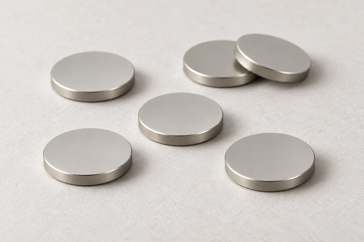
은·텅스텐 접점(AgW)은 전류를 전달하는 은과 아크 손실을 억제하는 텅스텐을 결합한 복합소재입니다. 은 함량이 같아도 상 분포·기공·표면과 캐리어 접합이 다르면 작동 결과가 달라질 수 있습니다. 좋은 접점의 기준은 성분표 한 줄보다 제조된 조직이 실제 개폐 조건에서 어떻게 변하는지에 있습니다.
분말과 성형에서 시작된 차이는 소결과 은 함침(용침, infiltration), 가공을 거쳐 접촉저항과 발열, 침식과 용착으로 이어집니다. 재료와 제조 경로를 선택할 때에는 접촉면, 배면층과 접합부를 구분하고 소재 검사부터 완성 조립품의 개폐 검증까지 연결해야 합니다.
복합소재의 구조
Ag/W 질량비·부피비와 상 분포·기공의 의미를 구분합니다.
제조와 접합의 연결
성형·소결·함침부터 접촉면과 캐리어 접합을 검토합니다.
실제 개폐 성능의 검증
저항·발열·침식·용착을 도면과 승인 기준에 연결합니다.
01재료 원리와 선택
은·텅스텐 접점의 작동 원리
은·텅스텐 접점(AgW)은 은의 전기·열 전달 능력과 텅스텐의 높은 내열성을 함께 사용하는 복합소재입니다. 전류가 흐르는 동안에는 저항과 온도상승을 억제해야 하고, 회로를 끊는 순간에는 아크에 의한 용융·비산과 손실을 견뎌야 합니다. 이 두 요구의 균형이 접점 재료를 선택하는 출발점입니다.
Ag와 W는 실용적인 접점 제조 조건에서 서로 거의 고용되지 않습니다. 따라서 AgW를 하나의 균일한 금속으로 녹여 만든 주조합금처럼 이해하면 제조와 검사 기준을 잘못 정하기 쉽습니다. 실제 성능에는 조성뿐 아니라 두 상의 분포, 잔류 기공과 계면 상태가 관여합니다.
통전과 개폐의 서로 다른 부담
닫힌 접점에서 전류는 표면 전체를 균일하게 통과하지 않습니다. 서로 맞닿은 미세 영역에 전류가 집중되고, 접촉력이나 표면막이 달라지면 그 경로도 변합니다. 여기에 접점 몸체와 접합부의 저항이 더해지므로 소재 전도도 하나로 완성품의 발열을 예측할 수는 없습니다.
| 작동 구간 | 주요 부담 | 함께 확인할 항목 |
|---|---|---|
| 연속 통전 | 좁은 전류 경로와 계면 발열 | 접촉력·저항·방열 경로 |
| 투입 | 돌입전류와 바운스 중 재아크 | 동작 파형·용착·재개방 힘 |
| 차단 | 아크 집중과 재료 손실 | 아크 지속·표면 형상·높이 감소 |
주접점과 아크 접점을 나누는 장치는 통전과 아크 부담을 서로 다른 부품에 분담할 수 있습니다. 반면 같은 접점이 두 역할을 담당하는 구조에서는 사용 후 접촉저항까지 재료 선정에 반영해야 합니다. 장치의 접촉 순서와 전류 전환 경로를 먼저 확인하면 잘못된 소재 비교를 줄일 수 있습니다.
고전류라는 표현도 연속 전류, 짧은 돌입전류와 고장 차단전류를 구분해야 의미가 있습니다. 같은 최댓값이라도 지속시간과 회로의 유도성, 개폐 빈도가 다르면 재료가 받는 부담은 달라집니다. 선정 자료에는 전류값과 함께 그 전류가 나타나는 동작을 적는 것이 유용합니다.
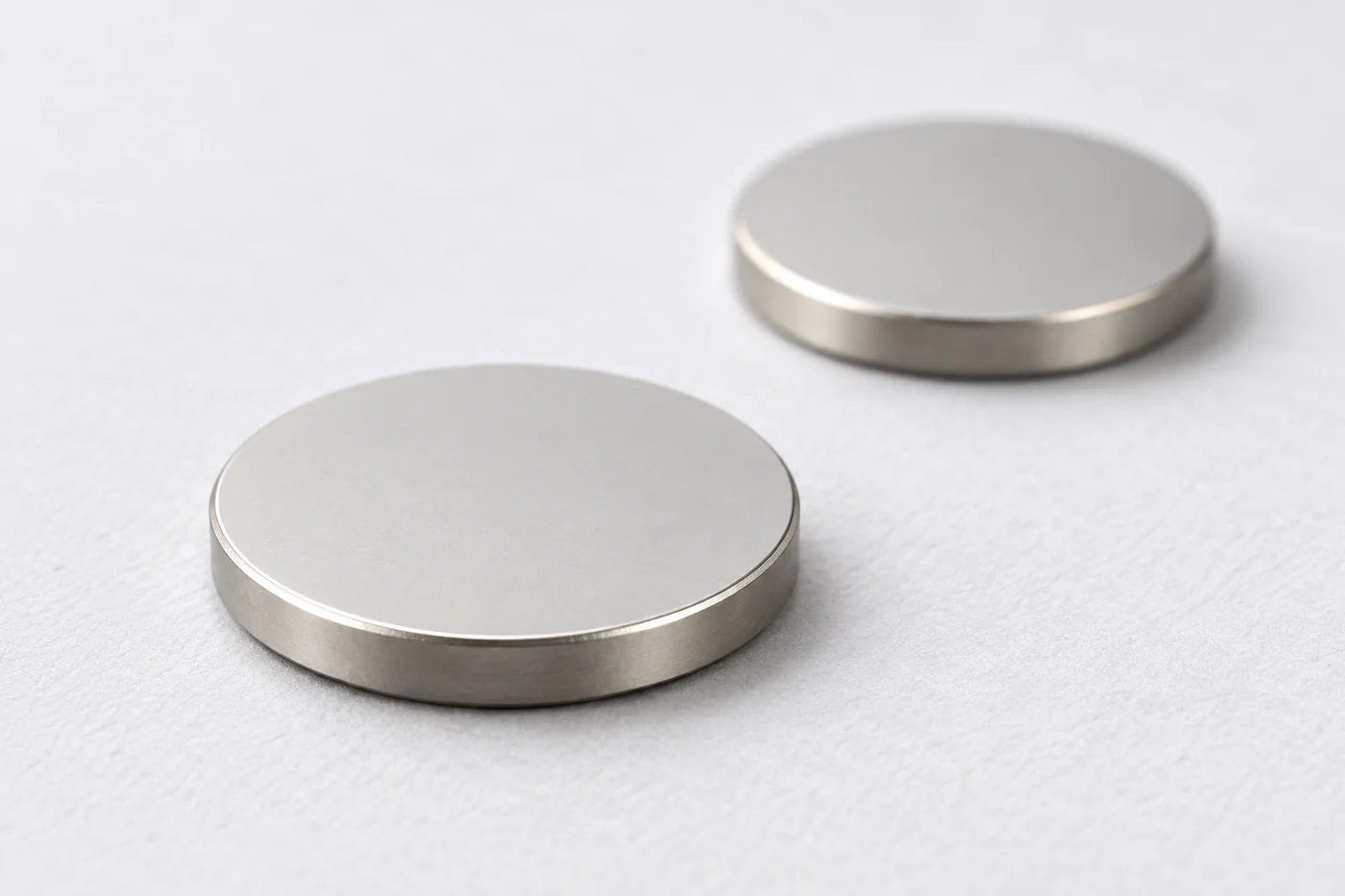
사진형 일러스트와 회전 가능한 3D는 접점 형상과 재료·공정의 관계를 설명하는 예시입니다. 특정 납품품의 조성·치수·정격이나 현미경 관찰 결과를 뜻하지 않습니다. 실제 제작 기준은 승인 도면과 시험 조건으로 정합니다.
AgW·AgWC·CuW의 선택 기준
AgW의 W는 금속 텅스텐이며, AgWC의 WC는 텅스텐 탄화물입니다. CuW는 은 대신 구리를 사용하는 별도의 복합소재입니다. 이름이 비슷하고 외관이 회색이라는 이유로 세 재료의 검사 기준이나 사용 환경을 서로 대체해서는 안 됩니다.
AgW는 아크 침식과 접점 용착을 억제해야 하는 개폐용 후보 재료입니다. 그러나 텅스텐 산화물이나 은 텅스테이트가 표면에 형성되면 통전 저항이 높아질 수 있습니다. 따라서 초기의 낮은 저항보다 반복 개폐 후의 저항 변화가 선정에 더 직접적인 정보를 줄 수 있습니다.
재료명보다 먼저 정할 사용 조건
| 재료군 | 구성상의 차이 | 비교 시험의 초점 |
|---|---|---|
| AgW | 은 + 금속 텅스텐 | 침식·사용 후 저항·용착의 균형 |
| AgWC | 은 + 텅스텐 탄화물 | 아크 후 표면 변화·균열·상대재 조합 |
| CuW | 구리 + 금속 텅스텐 | 사용 분위기·산화·연속 통전 요구 |
| AgSnO₂ | 은 + 산화주석 계열 | 해당 부하에서 개폐 수명·발열 비교 |
AgWC는 W를 같은 질량만큼 WC로 바꾼 AgW와 같지 않습니다. 탄화물의 밀도와 기계적 성질, 아크 중 반응이 다르므로 같은 질량비 비교만으로 우열을 정하기 어렵습니다. 공기 중 시험 결과를 진공·가스·액체 절연 환경으로 옮길 때에도 별도 확인이 필요합니다.
접촉하는 두 면의 재료를 반드시 같게 만들 필요는 없습니다. 한쪽의 침식이 더 큰 장치에서는 서로 다른 접점 재료를 조합해 저항과 손실의 균형을 맞추기도 합니다. 다만 기존 한쪽 재료만 바꾸면 재료 전이와 용착 거동도 변하므로 접점 쌍을 하나의 시험 단위로 다루어야 합니다.
선정 시험에는 전압과 전류 외에 AC·DC, 부하 종류, 개폐 속도, 접촉력과 바운스를 함께 기록합니다. 극성이 고정된 회로는 양쪽 접점의 질량과 형상 변화를 따로 비교하는 편이 좋습니다. 전기적 조건과 기계 동작을 고정해야 재료 변경의 영향을 분리할 수 있습니다.
후보 소재는 실제 불량 유형에서 좁히는 것이 효과적입니다. 심한 재료 손실, 개방 실패와 과도한 온도상승은 서로 다른 우선순위를 만듭니다. 세 현상을 한 개의 경도값이나 은 함량으로 해결하려 하기보다 현재 장치의 제한 요인을 먼저 정해야 합니다.
02조성과 미세조직
은·텅스텐 함량과 물성의 해석
은·텅스텐 접점의 함량 표기는 질량비와 부피비를 구분해야 합니다. 텅스텐은 같은 부피의 은보다 무겁기 때문에 W가 질량의 절반이라고 해서 조직 부피도 절반이 되는 것은 아닙니다. 재료명 뒤 숫자가 어느 성분의 질량비인지 공급자 규격에서 먼저 확인합니다.
기공과 첨가물이 없는 두 성분만 가정하고 밀도를 Ag 10.5 g/cm³, W 19.3 g/cm³로 두면 환산을 간단히 비교할 수 있습니다. 예를 들어 Ag 30 wt%·W 70 wt%의 100 g에는 Ag 약 2.86 cm³, W 약 3.63 cm³가 들어갑니다. 따라서 은은 질량으로 30%이지만 고체 부피로는 약 44%를 차지합니다.
| 계산 예시 | 은의 고체 부피 비율 | 기공 없는 이론 밀도 |
|---|---|---|
| Ag 50 wt% / W 50 wt% | 약 65% | 약 13.60 g/cm³ |
| Ag 40 wt% / W 60 wt% | 약 55% | 약 14.45 g/cm³ |
| Ag 30 wt% / W 70 wt% | 약 44% | 약 15.42 g/cm³ |
계산값과 납품 물성의 차이
위 계산은 상온 밀도를 이용한 설명용 예시이며 제품 합격 범위가 아닙니다. 실제 밀도에는 조성 편차, 첨가물과 기공이 영향을 줍니다. 상대 밀도는 해당 재료의 이론 밀도에 대한 비율이므로 서로 다른 조성을 같은 기준값으로 나누어 비교하면 안 됩니다.
공개 제조사 자료의 한 예에서 AgW50은 전도도 38 MS/m, AgW70은 31 MS/m로 제시됩니다. 이는 텅스텐 함량을 높이는 선택이 전도성과 함께 검토되어야 함을 보여주는 해당 자료의 대표값입니다. 공급사·제조 경로·검사 조건이 다른 재료에 같은 수치를 보증값으로 적용하지 않습니다.
전도도가 높더라도 개폐 후 표면막과 균열이 생기면 완성 접점의 저항은 증가할 수 있습니다. 반대로 높은 경도는 국부 눌림을 줄이지만 같은 접촉력에서 실접촉 면적을 작게 만들 수 있습니다. 벌크 물성은 재료 상태를 비교하는 지표이며 개폐 성능을 단독으로 대신하지 못합니다.
견적을 비교할 때에는 명목 조성에 더해 허용 범위, 첨가 원소, 밀도와 전도도 시험법을 같은 표에 정리합니다. 접합용 은층이나 도금이 있으면 분석 시 그 층의 포함 여부도 밝혀야 합니다. 서로 다른 시료 정의를 맞추는 작업이 작은 수치 차이를 해석하는 것보다 먼저입니다.
분말·상 분포·잔류 기공
같은 AgW 조성에서도 은이 넓게 뭉친 영역과 텅스텐 응집부가 함께 존재할 수 있습니다. 평균 성분 분석은 이를 하나의 값으로 합쳐 보여주므로 위치별 불균일을 놓칠 수 있습니다. 접촉면에서 두께 방향까지 조직을 살펴야 전류·열·균열의 경로를 이해할 수 있습니다.
은상이 연결되면 전류와 열이 이동할 경로를 제공합니다. 텅스텐 입자 사이의 연결은 함침 전에 골격 형상을 유지하는 데 필요하지만, 과도하게 이어진 취성 경로가 항상 유리하지는 않습니다. 반복 열충격에서 균열이 어디로 진행하는지까지 확인해야 연결성의 의미를 판단할 수 있습니다.
평균 입도보다 넓은 분말 관리
분말 입도 분포와 형상은 충전, 성형 밀도와 기공 통로를 함께 바꿉니다. 미세 분말은 표면적이 커지므로 산소와 오염, 응집의 영향을 더 주의해서 보아야 합니다. 입도가 작다는 이유만으로 균일한 조직이나 높은 수명을 보장할 수는 없습니다.
| 관찰 대상 | 문제가 되는 이유 | 유용한 확인 방법 |
|---|---|---|
| 은이 집중된 영역 | 국부 용융·재료 이동의 편차 | 여러 위치의 연마 단면 비교 |
| 텅스텐 응집부 | 연결 경로와 국부 취성의 편차 | 입자 분포·연속성·균열 대조 |
| 잔류 기공 | 유효 단면 감소와 손상 시작점 | 밀도와 단면 기공을 함께 확인 |
| 표면에서 내부로의 편차 | 접촉면 분석만으로 내부 상태 누락 | 두께 방향과 다른 방향 단면 |
분말 입고 시에는 조성·입도 외에 로트와 보관 이력, 필요한 순도 항목을 묶어 관리합니다. 혼합 후 시료는 한 곳만 채취하지 않고 채취 위치를 정합니다. 배합 성분이 맞더라도 충전과 이동 중 분리되면 성형품 간 편차가 생길 수 있기 때문입니다.
연마 중 입자가 빠져나간 자국은 실제 기공처럼 보일 수 있고, 연한 은이 번지면 작은 기공을 가릴 수 있습니다. 시편 제작 조건을 일정하게 유지하고 의심 영역은 다른 준비 조건이나 추가 단면으로 대조합니다. 이미지 분석의 숫자에는 시야 수, 배율과 분류 기준이 함께 있어야 합니다.
3D의 상 분리와 절단 보기는 은 경로, 텅스텐 분포와 기공의 관계를 공간적으로 보여줍니다. 단일 연마면의 면적 비율만으로 실제 3차원 연결성을 확정할 수는 없습니다. 조직 승인에는 여러 단면의 결과와 제조 이력, 실제 개폐 시험을 연결합니다.
AgW의 두 상과 연결 구조
INTERACTIVE 3D입자 형상과 개수를 단순화한 개념도입니다. 청회색 W와 밝은 Ag를 한 절단면에서 구별하며, 실제 현미경 조직이나 조성을 재현한 것은 아닙니다.
03분말야금과 함침
성형·소결과 함침 제조 경로
은·텅스텐 접점은 분말야금으로 두 성분의 분포와 형상을 만듭니다. 대표 경로에는 혼합 분말을 성형·소결·재압축하는 방식과 다공성 텅스텐 성형체에 은을 함침시키는 방식이 있습니다. 두 경로는 최초 분말의 역할과 기공을 처리하는 순서가 다릅니다.
성형·소결·재압축(PSR)에서는 배합된 분말을 압축해 형상을 만든 뒤 열처리로 입자 사이 결합을 발달시킵니다. 후속 재압축은 밀도와 치수를 조정하는 공정입니다. 접합용 배면층을 함께 성형하는 구조도 가능하므로 접촉면과 배면의 방향 관리가 중요합니다.
| 제조 경로 | 중간체 | 핵심 공정 관리 |
|---|---|---|
| 혼합 분말 성형·소결·재압축 | Ag/W가 함께 들어간 성형체 | 배합 균일성·밀도 분포·재압축 손상 |
| 액상 소결 | 저융점 성분이 일부 액상이 되는 성형체 | 액상량·형상 유지·수축 |
| 성형·소결·함침 | 연결 기공을 가진 텅스텐 골격 | 개방 기공·젖음·은 공급·잔류 기공 |
서로 다른 공정을 구분하는 기준
액상 소결은 성형체 안의 저융점 성분이 액상이 되어 치밀화에 참여하는 방식입니다. 함침은 외부에서 공급한 액체가 이미 있는 기공망을 채우는 방식입니다. 두 공정 모두 액체 은을 포함할 수 있지만 성형체 설계와 은 공급량을 정하는 방법은 같지 않습니다.
소결은 단순히 오래 가열할수록 좋은 공정이 아닙니다. 입자 사이 결합이 부족하면 취급이나 후공정에서 손상되기 쉽고, 함침 전 기공이 과도하게 줄거나 닫히면 액체가 들어갈 공간과 통로가 달라집니다. 목표는 강도·기공 구조·치수 변화가 함께 맞는 중간체입니다.
금형 성형에서는 충전량, 가압 방향과 배출 시 마찰이 위치별 밀도에 영향을 줄 수 있습니다. 모서리 균열이나 층상 결함이 보이면 최종 연마로 외관만 고치기보다 성형과 탈형 이력을 확인해야 합니다. 기준 시료의 단면과 공정 기록을 연결하면 발생 단계의 추적이 쉬워집니다.
공정 선택은 조성만으로 고정하지 않습니다. 형상, 접합층, 생산 수량과 필요한 조직·치수 범위를 함께 검토합니다. 공정 변경은 같은 성분을 유지하더라도 기공·분포·표면 상태를 바꿀 수 있으므로 변경 전후의 검사와 기능 결과를 비교해야 합니다.
은 함침과 기공 제어
함침 공정에서는 텅스텐 골격을 고체로 유지하면서 용융 은이 연결된 기공으로 들어가게 합니다. 은이 표면에 녹아 있다고 해서 내부 충전이 끝난 것은 아닙니다. 기공의 연결성, 젖음성과 내부 기체의 배출 경로가 함께 확보되어야 합니다.
작은 기공은 젖음 조건이 맞으면 모세관 작용에 기여하지만 흐름 저항도 커질 수 있습니다. 입구가 막히거나 닫힌 기공은 유지시간을 늘려도 같은 방식으로 채워지지 않습니다. 은 부족과 통로 불량을 구분하려면 공급량과 함께 함침 전후 단면을 확인해야 합니다.
온도·분위기·중간체의 연결
| 관리 변수 | 변화가 미치는 영향 | 공정 확인 자료 |
|---|---|---|
| 골격의 개방 기공 | 수용 가능한 은의 양과 흐름 경로 | 성형·소결 밀도와 대표 단면 |
| 표면 청정도·분위기 | 젖음과 산화·오염 상태 | 분말·열처리·분위기 기록 |
| 온도와 유지시간 | 용융·함침·조직 변화 | 실제 열 이력과 시료 위치 |
| 은 공급과 배치 | 충전 부족·잔류 은·배면층 | 투입 질량·잔류량·최종 단면 |
공개된 한 함침 연구는 Ag–1 wt% Ni를 사용하고 수소 분위기에서 1100°C와 1200°C, 1시간 조건을 비교했습니다. 보고된 상대 밀도는 연구 시료군에서 약 92.5–96% 범위였으며, 높은 온도가 모든 물성을 개선하지는 않았습니다. 이 결과는 특정 분말과 조성의 실험이며 양산 온도나 기공 합격 기준을 제시하지 않습니다.
이 사례의 실무적 의미는 함침 완료를 외관이나 공정명으로 판정하지 않는 데 있습니다. 실제 질량·치수·밀도와 단면을 연결하면 은이 충분히 들어갔는지, 국부 기공이 남았는지를 더 명확히 구분할 수 있습니다. 밀도 평균이 같아도 큰 기공이 한곳에 집중된 시료와 작게 분산된 시료는 별도 관찰이 필요합니다.
젖음 개선을 위한 소량 첨가 원소도 최종 재료의 일부입니다. 첨가량이나 원료를 변경하면 조직뿐 아니라 후속 접합과 전기적 거동의 확인 범위를 다시 정해야 합니다. 공급자 변경 시 명목 Ag/W 비율만 같다는 이유로 동일 재료로 처리하지 않습니다.
3D 공정 보기는 열린 기공을 따라 은이 채워지고 고체 골격이 남는 순서를 보여줍니다. 실제 충전 속도나 온도장을 계산한 결과는 아니므로 애니메이션 시간을 공정 시간으로 읽지 않습니다. 공정의 판단 근거는 함침 전 중간체와 최종 단면의 대응 관계입니다.
W 골격에서 Ag 함침 조직까지
INTERACTIVE 3D청회색 W 골격의 형태는 전 단계에서 유지됩니다. 옅은 외곽선은 관찰영역이며 아직 채워진 은을 뜻하지 않습니다. 실제 입도·공극률은 재현하지 않습니다.
04표면과 접합
접촉면 가공과 표면 상태
은·텅스텐 접점의 접촉면은 평탄도·곡률·높이와 표면 상태가 함께 작동합니다. 상대면에 한쪽 모서리부터 닿으면 초기 전류와 힘이 좁은 위치에 집중될 수 있습니다. 면의 거칠기만 낮추는 것보다 완성 조립품에서의 닿는 위치와 기울기를 먼저 확인해야 합니다.
가공·연마 과정은 연한 은과 단단한 텅스텐에 서로 다르게 작용합니다. 은의 번짐, 입자 탈락이나 모서리 손상을 구분하지 않으면 광택이 좋은 표면을 건전한 표면으로 오인하기 쉽습니다. 확대 외관과 필요 단면을 함께 보아 가공 흔적인지 내부 결함인지 판단합니다.
접촉면과 접합면의 별도 지정
| 면·위치 | 지정할 특성 | 혼동하기 쉬운 항목 |
|---|---|---|
| 상대재와 닿는 면 | 형상·높이·허용 표면 상태 | 광택과 전기적 성능 |
| 캐리어에 붙는 배면 | 접합층·도금·청정도 | 접촉면용 표면 요구 |
| 가장자리 | 모따기·칩·균열 기준 | 외관 버 제거와 균열 제거 |
| 검사 단면 | 절단 위치·연마 조건 | 시편 손상과 실제 기공 |
배면의 은층이나 접합용 도금은 브레이징 또는 용접을 돕기 위한 기능층일 수 있습니다. 접촉면의 은이 풍부한 표층과 목적이 다르므로 도면에서 위치와 처리 순서를 분리해야 합니다. 조립 방향이 뒤바뀌면 외형이 같아도 접합과 개폐 성능이 모두 달라질 수 있습니다.
세정 후 남은 가공유와 연마제는 접합 면의 젖음이나 접촉면 상태에 영향을 줄 수 있습니다. 세정 방법, 건조와 포장까지 하나의 납품 상태로 정의하면 검사 뒤 재오염을 줄이기 쉽습니다. 강한 세정이나 추가 연마도 승인된 층을 제거할 수 있으므로 임의의 후처리로 다루지 않습니다.
포장에서는 서로 부딪히는 모서리와 접촉면을 보호하고 재료 등급·표면 처리별 혼입을 막습니다. 입고 검사에서 색상이나 자성만으로 AgW 등급을 판별하지 않습니다. 식별 이력과 필요한 분석을 연결하는 편이 표면 외관에 기대는 것보다 신뢰할 수 있습니다.
재작업 기준에는 제거 가능한 표면 결함과 다시 승인해야 하는 구조 손상을 나누어 적습니다. 접촉면을 연마하면 높이와 곡률이 바뀌고, 배면을 연마하면 접합층 두께가 달라집니다. 최종 치수와 기능층을 함께 다시 확인해야 재작업이 새 불량을 만들지 않습니다.
배면층·브레이징·캐리어 접합
AgW 팁의 성능은 캐리어와 연결된 뒤 완성됩니다. 접촉면에서 들어온 전류와 열이 팁, 접합층과 캐리어를 지나므로 접합부는 기계적 고정 이상의 역할을 합니다. 외부에서 보이는 필렛이 양호해도 내부 접합 면적과 빈 공간의 위치는 별도로 확인해야 합니다.
함침형 팁은 배면의 은 잉여층을, 다른 제조 경로는 별도의 Ag·AgNi 계열 배면층을 활용할 수 있습니다. 브레이즈 합금층을 미리 부여하는 공급 형태도 있습니다. 실제 조립법은 접점 본체 이름보다 배면 구조와 캐리어 재질을 기준으로 선택합니다.
접합 면적과 열 이력
| 관리 항목 | 발생 가능한 문제 | 연결할 검사 |
|---|---|---|
| 배면층과 브레이즈 적합성 | 젖음 부족·계면 불연속 | 단면·성분·파단 위치 |
| 간극과 합금 공급 | 미충전·국부 과잉·기울기 | 착좌 상태·접합 분포 |
| 가열·가압·냉각 | 캐리어 연화·변형·균열 | 열 이력·치수·기계 특성 |
| 플럭스·잔류물 | 공극·오염·부식 우려 | 세정 상태·잔류물·환경 시험 |
가열은 브레이즈를 녹이는 데 충분해야 하지만 주변 부품에도 열 이력을 남깁니다. 캐리어가 탄성 기능을 갖는다면 경도와 작동력 변화를, 위치를 유지하는 부품이라면 접합 후 휨과 높이를 확인합니다. 팁의 접합 강도만 합격시키면 캐리어의 기능 변화를 놓칠 수 있습니다.
접합 면적은 전체 비율과 결함 위치를 함께 평가합니다. 같은 미접합 비율이라도 전류가 들어오는 가장자리나 주요 방열 경로에 결함이 모이면 영향이 달라집니다. 단면은 선택한 절단면만 보여주므로 전체 분포를 보려는 검사와 역할을 나누어야 합니다.
전단·인장 시험에서는 최대 하중뿐 아니라 어디가 파괴되었는지도 기록합니다. 접합 계면, 배면층, AgW 내부와 캐리어의 파괴는 같은 숫자라도 의미가 다릅니다. 초음파나 방사선 검사를 적용할 때에는 작은 형상과 재료 대비에 맞는 검출 능력을 먼저 검증합니다.
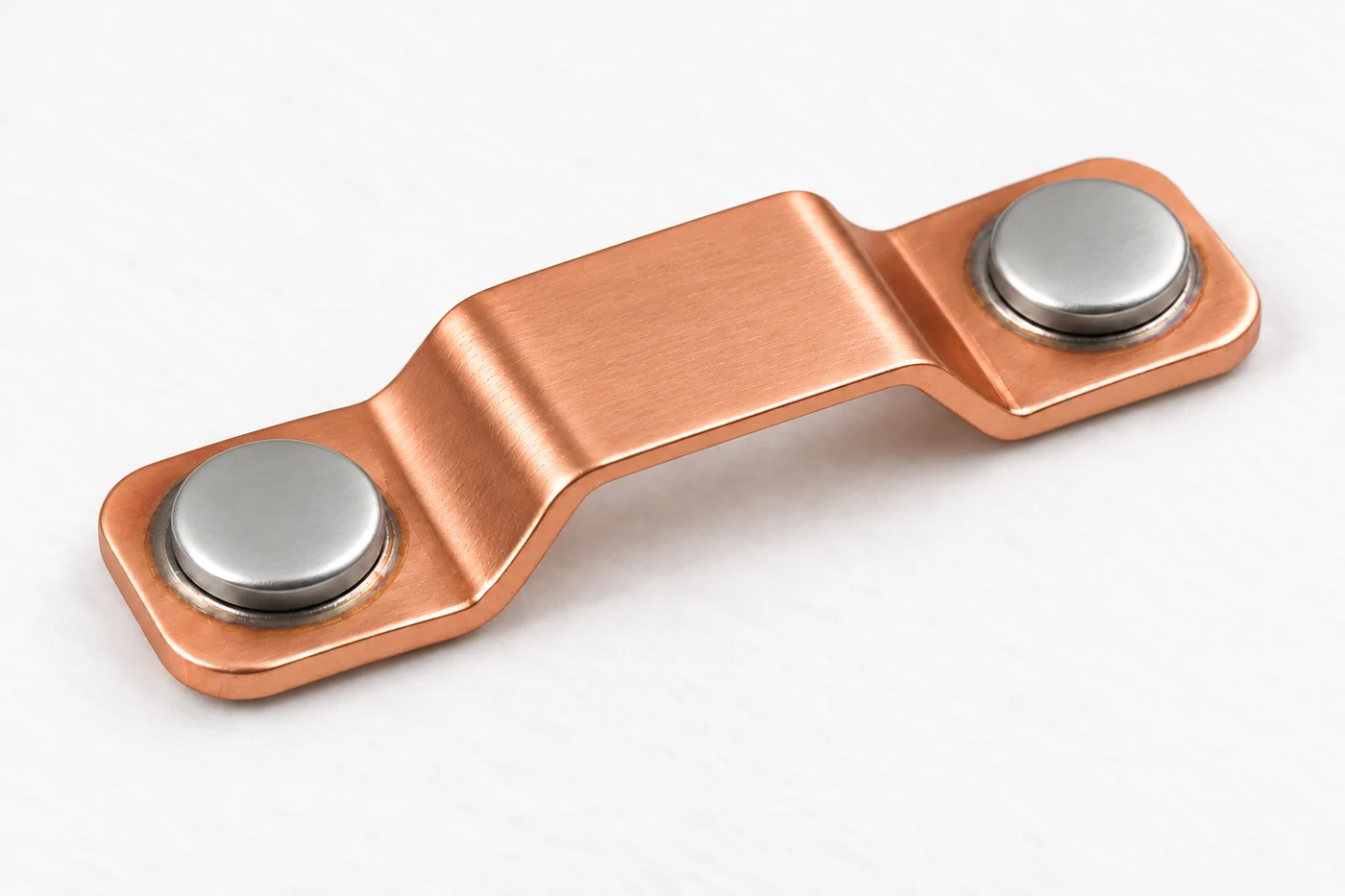
AgW 본체를 연성이 큰 단일 금속 리벳처럼 눌러 퍼뜨리는 구조로 해석하지 않습니다. 기계 체결용 샹크가 필요한 제품은 다른 재료와 복합 구조를 사용할 수 있으므로 단면 정의가 우선입니다. 사진의 캐리어와 팁 배치는 이 전류·접합 경로를 이해하기 위한 형상 예시입니다.
05개폐 손상과 열 거동
아크 침식·표면막·용착
아크 침식은 표면이 일정하게 닳는 현상만을 뜻하지 않습니다. 은의 용융·증발과 액적 비산, 텅스텐이 드러난 층의 균열과 탈락이 함께 나타날 수 있습니다. 남아 있는 형상과 내부 손상은 질량 손실 하나만으로 설명하기 어렵습니다.
공개된 AgW 개폐 후 조직 연구에서는 은이 줄어든 표면, 텅스텐 골격 균열과 내부 기공이 관찰되었습니다. 이는 반복 아크가 초기 조직을 바꾸고 다음 동작의 전류·열 경로에도 영향을 줄 수 있음을 보여줍니다. 특정 시료의 손상 형태를 모든 부하에서 같은 순서로 발생하는 법칙으로 적용하지는 않습니다.
서로 다른 손상을 나누는 관찰
| 손상 또는 변화 | 관찰 항목 | 설계·공정에 되돌릴 정보 |
|---|---|---|
| 침식·비산 | 질량·높이·국부 크레이터 | 아크 집중·유효 접점 두께 |
| 재료 전이 | 양쪽 접점의 증가·감소와 돌기 | 극성·동작·상대 재료 |
| 표면막 증가 | 사용 후 저항·표면 분석 | 환경·아크 이력·접촉력 |
| 균열·박리 | 단면 깊이·방향·기공 연계 | 조직·열충격·접합 영향 |
| 용착 | 재개방 힘·개방 실패·용착 흔적 | 돌입·바운스·구동 여유 |
산화물과 은 텅스테이트가 포함된 표면층은 전류가 통하는 미세 영역을 제한할 수 있습니다. 사용 후 온도상승이 커졌을 때에는 AgW 벌크 전도도뿐 아니라 표면 조성과 접촉력 변화를 분리해서 확인합니다. 세정 전후 결과가 다르면 세정이 제거한 것이 무엇인지도 기록해야 합니다.
용착은 두 면 사이에 생긴 금속 연결을 구동력이 충분히 끊지 못하는 문제입니다. 투입 중 바운스가 반복되면 재아크와 국부 용융이 더해질 수 있습니다. 재료의 내융착성을 높이는 선택과 바운스·속도·접촉력의 개선은 함께 검토해야 합니다.
아크의 전압·전류를 시간에 따라 기록하면 사건별 에너지 차이를 비교할 수 있습니다. 다만 전기적으로 계산한 아크 에너지 전체가 한쪽 접점에 흡수되는 것은 아닙니다. 아크가 이동하는 경로, 지속시간과 양쪽 표면의 손상을 함께 보아야 국부 침식의 원인을 좁힐 수 있습니다.
재료 전이가 있으면 한쪽 질량 감소를 전체 소모량으로 해석하기 어렵습니다. 양쪽 접점의 질량, 두께와 표면 지형을 함께 기록하고 극성도 유지해 비교합니다. 짧은 시험의 평균 손실을 장기 수명으로 직선 외삽하기 전에는 표면 변화와 파괴 양상이 유지되는지 확인해야 합니다.
접촉력·전류·열의 결합
접촉력을 높이면 미세 접촉부의 변형과 통전 영역이 달라집니다. 그러나 필요한 힘은 접점 곡률·경도·표면막과 기구의 움직임에 따라 정해야 합니다. 힘만 높이는 변경은 캐리어 변형이나 구동 부담을 늘릴 수 있으므로 닫힘 위치와 실제 힘을 함께 측정합니다.
전류는 상대 접촉면에서 AgW 몸체, 배면층과 접합부를 거쳐 캐리어로 이동합니다. 어느 한 구간이 좁거나 저항이 커지면 그 부위의 발열이 전체 온도에 영향을 줍니다. 따라서 양단 저항이 증가했다는 사실만으로 AgW 조성에 원인을 돌리지 않습니다.
발열량과 온도상승의 구분
정상 DC 전류에서 관심 구간의 발열은 P = I²R로 계산할 수 있습니다. 설명용으로 100 A와 100 µΩ을 가정하면 그 구간의 발열은 1 W이며, 저항만 200 µΩ으로 증가하면 2 W가 됩니다. 이는 특정 접점의 정격이나 허용값을 제시하는 계산이 아닙니다.
| 평가 대상 | 직접 얻는 정보 | 함께 필요한 조건 |
|---|---|---|
| 구간 전압강하·저항 | 어디에서 전기 손실이 늘었는지 | 검출점·전류·온도·접촉력 |
| 온도 측정 | 열 발생과 방열을 합친 결과 | 주변 온도·센서 위치·설치 상태 |
| 힘–변위 | 접촉 상태와 구동 여유 | 조립 기준·마모·열 이력 |
| 동작 파형 | 바운스·분리·아크 지속 | 측정 대역·동기화·부하 조건 |
온도상승은 발생 열뿐 아니라 캐리어 단면, 접합부와 외부 방열 조건에도 영향을 받습니다. 같은 접점과 전류라도 연결 도체와 설치 방식이 다르면 온도가 달라질 수 있습니다. 시험 성적서에 주변 온도와 연결 조건을 남겨야 재시험의 차이를 해석할 수 있습니다.
열화상으로 작은 금속 접점을 볼 때에는 반사와 방사율, 측정 지점의 크기를 주의해야 합니다. 밝게 보이는 영역이 곧 실제 최고온도라는 가정은 피하고 접촉식 센서 등과 대조해 방법을 정합니다. 센서 부착 자체가 작은 부품의 방열을 바꾸는지도 함께 고려합니다.
3D의 분해·절단 보기는 접촉면, 팁, 접합층과 캐리어를 따라 전류와 열이 지나가는 위치를 구분합니다. 표시된 경로는 계산된 전류밀도나 온도 해석 결과가 아닙니다. 실제 이상 위치는 구간 측정과 조립품 시험으로 확인합니다.
AgW 접점과 구리 캐리어의 접합
INTERACTIVE 3D연속된 접합층이 접점과 캐리어를 연결하는 이상화한 단면입니다. 실제 접합에서는 젖음·간극·열 이력과 표면 상태에 따라 계면의 연속성과 반응 상태가 달라집니다.
06검사와 제작 승인
소재 검사와 개폐 내구 검증
검사 계획은 입고 재료, 접합 전 팁과 완성 조립품을 나누어 구성합니다. 조성·밀도·경도는 소재 상태를, 접합과 치수는 조립 상태를, 저항·발열·개폐 시험은 작동 결과를 보여줍니다. 한 단계의 합격으로 다른 단계의 검사를 대신하지 않는 것이 핵심입니다.
밀도는 시편의 개방 기공에 맞는 방법으로 측정합니다. ASTM B962는 아르키메데스 원리를 사용하는 분말야금 제품의 밀도 시험을 다루며, 액체가 침투할 수 있는 시편은 기공 처리 방식이 중요합니다. 실제 조성과 표면층을 반영한 기준 밀도, 시료 온도와 반복 측정 편차도 함께 관리합니다.
| 검증 단계 | 주요 항목 | 판정 자료의 구성 |
|---|---|---|
| 소재 | 조성·밀도·경도·전도도 | 시험법·시료 정의·로트 |
| 조직·표면 | 상 분포·기공·균열·기능층 | 위치별 단면과 외관 기준 |
| 접합품 | 접합 분포·강도·치수·힘 | 파괴 위치와 조립 기준 |
| 전기·열 | 저항·전압강하·온도상승 | 전류·검출 위치·주변 조건 |
| 개폐 내구 | 침식·용착·동작·사용 후 저항 | 실제 부하와 단계별 중간 측정 |
재현 가능한 저항과 수명 측정
낮은 저항은 전류 공급선과 전압 검출선을 나눈 4선식으로 측정하면 리드 저항의 영향을 줄일 수 있습니다. 그러나 검출점 사이에 들어 있는 몸체·접합·접촉 계면의 저항을 자동으로 분리하지는 않습니다. 검출 위치, 접촉력, 인가 전류와 측정 시간을 고정하고 열기전력의 영향이 크면 검증된 반전·오프셋 보상법을 사용합니다.
작은 측정 전류의 결과와 정격 통전 중 결과는 구분해서 보관합니다. 측정 전류가 표면막이나 온도를 바꾸면 처음 상태의 저항과 다른 값이 나올 수 있습니다. ASTM B539의 정적 접속 저항 시험과 장치의 동적 개폐 시험도 목적이 다르므로 하나의 저항 기준으로 합치지 않습니다.
내구 시험은 완료 횟수만 기록하지 않고 중간 구간의 저항, 온도, 질량·높이와 개방 상태를 함께 남깁니다. 불량이 마지막에만 나타나는지, 초기에 급변한 뒤 안정되는지에 따라 원인과 대책이 달라집니다. 시험 종료 뒤에는 세정·분해 전에 표면과 조립 상태를 먼저 기록하는 편이 분석에 유리합니다.
AgW 소재 규격인 ASTM B631과 차단기 제품 규격인 IEC 60947-2는 다루는 대상이 다릅니다. 소재가 지정 요구에 맞더라도 완성 차단기의 차단 능력이나 수명이 자동으로 입증되지는 않습니다. 실제 장치 종류와 사용 조건에 맞는 규격 판본·시험 항목·합격 기준을 승인 문서에 연결합니다.
도면·발주·양산 승인
은·텅스텐 접점의 제작 검토는 재료명과 외형만으로 끝나지 않습니다. 접촉면과 배면, 캐리어와 접합 방식, 실제 개폐 조건이 같은 개정의 자료로 연결되어야 합니다. 이 정보가 모이면 소재 선택부터 시험 시료의 공급 상태까지 일관되게 정할 수 있습니다.
도면에는 Ag/W 함량의 기준과 허용 범위, 필요한 첨가 원소 및 배면층을 구분합니다. 기능상 중요한 높이·곡률·평탄도와 접합 후 위치를 먼저 지정하고 단순 외관치와 나누어 관리합니다. 모든 치수의 공차를 일괄 강화하기보다 성능에 직접 영향을 주는 항목을 좁히는 편이 효과적입니다.
| 발주 정보 | 필요한 내용 | 확인 목적 |
|---|---|---|
| 소재·층 구조 | 조성 기준·첨가물·배면·표면 처리 | 동등 재료와 공정 범위 |
| 형상·조립 | 기준면·접촉 형상·캐리어·접합 | 기능 치수와 공정 순서 |
| 작동 조건 | 전압·전류·부하·속도·힘·환경 | 소재 후보와 검증 조건 |
| 검사·승인 | 시료 수·시험법·판정·보관 시료 | 개발과 납품의 일치 |
| 공급·변경 | 포장·식별·수량·변경 통보 | 혼입 방지와 추적성 |
승인 기준과 변경 관리
개발 시료는 소재 검사, 접합 검증과 완성 장치 시험의 결과를 연결해 승인합니다. 이후 양산에서는 전수 확인할 항목과 파괴 시험으로 주기 확인할 항목을 위험도와 공정 안정성에 맞춰 나눕니다. 검사 수량과 주기는 편의가 아니라 어떤 불량을 놓치지 않으려는지에서 정합니다.
분말 공급처, 입도, 첨가물이나 소결·함침 조건이 바뀌면 같은 도면에서도 조직이 달라질 수 있습니다. 배면층·브레이즈·캐리어 또는 세정 변경 역시 전류 경로와 접합에 영향을 줄 수 있습니다. 변경 항목과 영향받는 기능을 묶어 재검증 범위를 정하고 승인 이력을 남깁니다.
원가는 은 사용량만으로 비교하기 어렵습니다. 성형·가공 수율, 배면층과 접합 공정, 파괴 검사와 기능 시험이 함께 반영됩니다. 은 비율이나 팁 두께를 줄이는 변경은 단가 계산과 동시에 발열·침식 후 잔여 두께·접합 여유를 다시 검토해야 합니다.
제작 상담에는 2D 도면과 조립도, 요구 재료 또는 비교 후보, 상대 접점 정보와 부하 조건을 함께 준비하면 좋습니다. 팁 단품 공급과 캐리어 접합품 공급의 범위를 구분하고 필요한 검사 기록을 지정합니다. 아이디메탈의 전기접점·브레이징 관련 제작 검토도 이 입력 자료를 기준으로 구체화할 수 있습니다.
English Edition · Silver–Tungsten Contacts (AgW): Composite Manufacturing and Quality Control for High-Current Switching
Silver–tungsten contacts (AgW) combine current-carrying silver with tungsten that helps resist arc-driven loss. Equal silver contents can produce different operating results when phase distribution, pores, surfaces and carrier attachment differ. Evaluating a contact requires understanding how its manufactured structure changes under actual switching duty, beyond a composition line.
Differences originating in powders and pressing pass through sintering, infiltration and finishing to influence resistance, heating, erosion and welding. Material and route selection must distinguish the mating face, backing and attachment, then connect material inspection to switching validation of the finished assembly.
Composite structure
Distinguish mass and volume fractions, phase distribution and pores.
Manufacturing and attachment
Connect pressing, sintering and infiltration to faces and carrier joints.
Switching validation
Relate resistance, heating, erosion and welding to drawings and approval.
01Material principles and selection
How silver–tungsten contacts work
Silver–tungsten contacts (AgW) combine the electrical and thermal transport of silver with the heat resistance of tungsten. During current carrying, resistance and temperature rise must remain controlled. During interruption, the contact must withstand arc-driven melting, ejection and material loss. Balancing these duties is the starting point for material selection.
Ag and W have negligible mutual solubility under practical contact-manufacturing conditions. Treating AgW as a uniform cast alloy can therefore lead to unsuitable manufacturing and inspection requirements. Performance depends on phase distribution, residual pores and interfaces as well as overall composition.
Different demands during carrying and switching
Current through a closed contact does not spread uniformly across its apparent face. It concentrates at microscopic contacting regions, whose condition changes with force and surface films. Bulk and attachment resistance add to this interface contribution, so material conductivity alone cannot predict the temperature of the complete assembly.
| Operating interval | Main demand | Associated checks |
|---|---|---|
| Continuous carrying | Restricted current paths and interface heating | Force, resistance and heat-removal path |
| Making | Inrush and renewed arcing during bounce | Motion waveforms, welding and reopening force |
| Breaking | Arc concentration and material loss | Arc duration, surface profile and height loss |
A device with separate main and arcing contacts can assign carrying and arc duties to different parts. Where one contact performs both roles, resistance after arcing also becomes a material-selection criterion. Establishing the engagement sequence and current-transfer path first prevents comparisons between contacts serving different functions.
High current needs to be separated into continuous current, short inrush and fault-interruption current. Equal peak values can impose different demands when duration, circuit inductance and operating frequency differ. A selection brief should identify the operating event alongside its current value.
The photographic illustrations and interactive 3D models explain contact geometry and material–process relationships. They do not identify the composition, dimensions or rating of a supplied product, or represent measured microscopy. Approved drawings and test conditions establish the actual manufacturing requirements.
Choosing between AgW, AgWC and CuW
W in AgW is metallic tungsten; WC in AgWC is tungsten carbide. CuW is a separate composite using copper instead of silver. Similar names and a gray appearance do not make their acceptance criteria or operating environments interchangeable.
AgW is a candidate where arc erosion and contact welding must be controlled. However, tungsten oxides or silver tungstates at the surface can raise carrying resistance. Resistance evolution after repeated switching may therefore inform selection more directly than a low initial reading.
Define service conditions before the material name
| Family | Constituent difference | Focus of comparative tests |
|---|---|---|
| AgW | Silver + metallic tungsten | Balance of erosion, post-duty resistance and welding |
| AgWC | Silver + tungsten carbide | Post-arc surface changes, cracking and counterpart |
| CuW | Copper + metallic tungsten | Atmosphere, oxidation and continuous carrying |
| AgSnO₂ | Silver + tin-oxide system | Switching endurance and heating at the specified load |
AgWC is not AgW with an equal mass of W simply replaced by WC. Differences in carbide density, mechanical behavior and reactions during arcing make an equal-mass comparison insufficient. Results obtained in air also require separate assessment before application in vacuum, gas or liquid-insulated environments.
The two mating faces do not always need identical materials. An asymmetric pair can balance resistance and loss where one side erodes more severely. Changing only one member also changes transfer and welding behavior, however, so the pair must be treated as the test unit.
Record AC or DC, load type, opening and closing speeds, force and bounce alongside voltage and current. With fixed polarity, compare mass and profile changes separately for the two contacts. Controlling both electrical duty and mechanical motion helps isolate the effect of a material change.
Narrow the candidates using the observed failure mode. Severe loss, failure to reopen and excessive temperature rise create different priorities. Identify the limiting behavior of the device before trying to solve all three with a single hardness value or silver percentage.
02Composition and microstructure
Interpreting composition and bulk properties
Composition in silver–tungsten contacts requires a clear distinction between mass fraction and volume fraction. Tungsten is heavier than silver for an equal volume, so half the mass does not imply half the microstructural volume. First establish which constituent and basis the supplier’s grade number denotes.
A simple conversion assumes two constituents without pores or additives, using 10.5 g/cm³ for Ag and 19.3 g/cm³ for W. In 100 g of Ag 30 wt%–W 70 wt%, silver occupies approximately 2.86 cm³ and tungsten 3.63 cm³. Silver therefore accounts for about 44% of the solid volume despite representing 30% of its mass.
| Illustrative composition | Silver fraction of solid volume | Pore-free theoretical density |
|---|---|---|
| Ag 50 wt% / W 50 wt% | About 65% | About 13.60 g/cm³ |
| Ag 40 wt% / W 60 wt% | About 55% | About 14.45 g/cm³ |
| Ag 30 wt% / W 70 wt% | About 44% | About 15.42 g/cm³ |
Calculated values and supplied properties
These room-temperature calculations are explanatory examples, not product acceptance limits. Actual density is affected by composition variation, additives and pores. Relative density uses the theoretical density of the particular material; different compositions must not be divided by one common reference value.
One public manufacturer datasheet lists conductivity of 38 MS/m for AgW50 and 31 MS/m for AgW70. These representative values illustrate why increasing tungsten content must be considered together with conductivity. They are not guaranteed values for materials from another supplier, process route or inspection condition.
High bulk conductivity cannot prevent a rise in assembled resistance caused by films or cracks after switching. Greater hardness can reduce local indentation while also reducing real contact area at a given force. Bulk properties characterize material condition but cannot independently establish switching performance.
Compare nominal composition together with allowed variation, additives and the density and conductivity test methods. If a silver backing or coating is present, state whether it is included in chemical analysis. Aligning specimen definitions comes before interpreting small numerical differences.
Powders, phase distribution and residual pores
A nominal AgW composition can contain both large silver-rich regions and tungsten agglomerates. Bulk chemistry combines them into one average and may miss local nonuniformity. Examining the face and through-thickness microstructure helps explain current, heat and crack paths.
Connected silver regions provide paths for current and heat. Connections between tungsten particles support the preform before infiltration, but excessive brittle continuity is not automatically beneficial. The significance of connectivity must include the paths taken by cracks under repeated thermal shock.
Powder control beyond average particle size
Powder size distribution and shape affect filling, compact density and pore channels together. Fine powders have more surface area, making oxygen, contamination and agglomeration important considerations. A smaller average size does not by itself guarantee uniform microstructure or long life.
| Feature | Why it matters | Useful examination |
|---|---|---|
| Silver-rich region | Local variation in melting and transfer | Polished sections from multiple positions |
| Tungsten agglomerate | Variation in continuity and local brittleness | Particle distribution, contiguity and crack comparison |
| Residual pore | Reduced effective section and damage initiation | Density together with sectioned porosity |
| Face-to-interior variation | Surface analysis can miss internal condition | Through-thickness and differently oriented sections |
Incoming powder control should connect composition and size to lot identity, storage history and required purity checks. Define sampling locations after blending rather than sampling one convenient point. Correct overall blending proportions do not exclude separation during handling or filling, which can create part-to-part variation.
Particle pull-out during polishing can resemble a real pore, while smeared silver can conceal small voids. Keep specimen preparation consistent and check questionable regions using an additional section or preparation condition. Image-analysis results need the field count, magnification and classification rules alongside the reported number.
Phase isolation and cutaway views in the 3D model show the spatial relationship between silver paths, tungsten and pores. Area fractions from one polished plane cannot establish the actual three-dimensional connectivity. Microstructural acceptance should connect multiple sections to process history and functional switching tests.
Two phases and connected paths in AgW
INTERACTIVE 3DParticle shapes and counts are deliberately simplified. Blue-grey W and pale Ag share a flush section; this is not a reconstruction of microscopy or composition.
03Powder metallurgy and infiltration
Pressing, sintering and infiltration routes
Powder metallurgy establishes the constituent distribution and geometry of silver–tungsten contacts. Representative routes include pressing, sintering and repressing a blended powder, and infiltrating a porous tungsten preform with silver. They differ in the role of the initial powder and the sequence used to manage porosity.
In press–sinter–repress processing, a powder blend is compacted and heat treated to develop interparticle bonding. Repressing subsequently adjusts density and dimensions. A joining backing may be compacted as a separate layer, making identification of the contact face and underside important.
| Route | Intermediate | Key process controls |
|---|---|---|
| Blend, press, sinter and repress | Compact containing Ag and W | Blend uniformity, density distribution and repressing damage |
| Liquid-phase sintering | Compact with a molten lower-melting constituent | Liquid amount, shape stability and shrinkage |
| Press, sinter and infiltrate | Tungsten skeleton with connected pores | Open porosity, wetting, silver supply and remaining pores |
Distinguishing the process routes
During liquid-phase sintering, a lower-melting constituent already inside the compact becomes liquid and participates in densification. In infiltration, externally supplied liquid fills an existing pore network. Both may involve liquid silver, but they require different approaches to preform design and silver quantity.
Longer heating is not automatically better sintering. Insufficient bonding leaves the intermediate vulnerable during handling, while excessive closure or shrinkage of pores before infiltration changes the available volume and access paths. The target intermediate must balance strength, pore structure and dimensional change.
In die pressing, fill quantity, loading direction and friction during ejection can influence local density. Edge cracks or lamination require examination of pressing and ejection history rather than cosmetic removal during finishing. Relating reference sections to process records helps locate the stage at which damage begins.
Composition alone does not fix the route. Geometry, backing construction, quantity and required microstructure and dimensional ranges must be considered together. A process change can alter pores, distribution and surface condition without changing nominal chemistry, requiring comparative inspection and functional results.
Silver infiltration and pore control
In infiltration, molten silver enters connected pores while the tungsten skeleton remains solid. A molten pool on the surface does not demonstrate complete internal filling. Pore connectivity, wetting and a route for displaced gas must all be available.
Small pores can support capillary action when wetting is favorable, but they can also increase resistance to flow. Blocked entrances and closed pores are not filled simply by extending the hold. Distinguishing insufficient silver from inaccessible pathways requires checking both supplied quantity and sections before and after infiltration.
Temperature, atmosphere and the preform
| Control variable | Effect of variation | Process evidence |
|---|---|---|
| Open porosity of the skeleton | Silver capacity and flow paths | Compact/sintered density and representative sections |
| Cleanliness and atmosphere | Wetting, oxidation and contamination | Powder, furnace and atmosphere records |
| Temperature and hold | Melting, infiltration and structural evolution | Actual thermal history and specimen position |
| Silver supply and placement | Incomplete filling, surplus silver and backing | Input mass, remaining silver and final section |
One published infiltration study compared Ag–1 wt% Ni at 1100°C and 1200°C for one hour in hydrogen. Reported relative densities for the studied specimens were approximately 92.5–96%, and the higher temperature did not improve every property. These results concern particular powders and compositions, not universal production temperatures or pore acceptance limits.
The practical lesson is to avoid judging infiltration from appearance or the route name. Linking mass, dimensions, density and sections clarifies whether sufficient silver entered and whether local pores remain. Equal average density does not remove the need to distinguish a concentrated large void from small dispersed pores.
A minor addition used to improve wetting remains part of the final material. Changing that addition or its source requires reviewing the validation scope for microstructure, joining and electrical behavior. Matching nominal Ag/W proportions alone does not establish equivalence when suppliers change.
The 3D process view shows silver filling accessible pores while the solid skeleton remains. It does not calculate filling velocity or temperature, so animation duration is not a processing time. The useful manufacturing evidence is the relationship between the initial preform and the finished section.
From a W skeleton to an infiltrated AgW structure
INTERACTIVE 3DThe blue-grey W skeleton remains fixed through all stages. The pale outline denotes an observation volume, not silver that has already filled it. Particle size and porosity are not reproduced.
04Surfaces and attachment
Contact-face finishing and surface condition
Flatness, curvature, height and surface condition act together at the face of a silver–tungsten contact. Edge-first engagement can concentrate the initial current and force in a small region. Establish the location and alignment of engagement in the finished assembly before focusing only on lower roughness.
Machining and polishing act differently on soft silver and hard tungsten. Silver smearing, particle pull-out and edge damage must be distinguished from a sound finish. Magnified surface inspection, supported by sections where needed, separates processing artifacts from underlying defects.
Specify the contact face and joining face separately
| Face or location | Characteristics to specify | Common confusion |
|---|---|---|
| Mating face | Profile, height and permitted surface condition | Luster versus electrical performance |
| Carrier attachment face | Backing, coating and cleanliness | Requirements intended for the mating face |
| Edge | Chamfer, chips and crack criteria | Deburring versus removal of a crack |
| Inspection section | Section location and preparation | Preparation damage versus actual pores |
A silver backing or joining coating can be a functional layer that enables brazing or welding. Its purpose differs from a silver-rich surface at the mating face, so drawings should distinguish location and treatment sequence. Reversing the part can change both attachment and switching behavior even when the outline appears identical.
Residual oil and abrasive can affect joining-face wetting or mating-surface condition. Define cleaning, drying and packaging as part of the delivered state to reduce recontamination after inspection. Aggressive cleaning or additional polishing can remove an approved layer and should not be treated as an unrestricted corrective operation.
Packaging should protect edges and working faces from mutual impact and prevent mixing of grades or finishes. Color or magnetic response alone does not establish an AgW grade at incoming inspection. Traceable identification combined with the required analysis is more reliable than surface appearance.
Rework criteria should separate removable surface defects from structural damage requiring renewed approval. Polishing a face changes height and curvature; polishing the underside changes backing thickness. Recheck final geometry and functional layers together so that rework does not introduce a new defect.
Backings, brazing and carrier attachment
An AgW tip performs as part of its attached carrier. Current and heat pass through the tip, joint and carrier, making attachment more than a mechanical fastening. A satisfactory external fillet does not establish internal bonded area or the location of voids.
An infiltrated tip may use excess silver on its underside, while another route may provide a separate Ag or AgNi backing. Some supply forms include a pre-applied braze alloy layer. Select attachment using the actual backing construction and carrier material rather than the contact-body name alone.
Bonded area and thermal history
| Control item | Possible problem | Associated inspection |
|---|---|---|
| Backing and braze compatibility | Incomplete wetting or discontinuous interface | Section, composition and fracture location |
| Gap and alloy quantity | Incomplete filling, local surplus or tilt | Seating and bond distribution |
| Heating, loading and cooling | Carrier softening, distortion or cracking | Thermal history, dimensions and mechanical properties |
| Flux and residue | Voids, contamination or corrosion concerns | Cleanliness, residue and environmental tests |
Heating must melt the braze but also changes the thermal history of surrounding parts. For a compliant carrier, check hardness and operating-force changes; for a locating member, check distortion and height after attachment. Passing tip retention alone can miss changes in carrier function.
Assess bonded fraction together with defect position. Equal unbonded fractions can have different effects when defects cluster near the current entrance or an important heat path. A section reveals only its selected plane and should be distinguished from methods intended to assess the full joint distribution.
In shear or tensile testing, record fracture location as well as maximum load. Failure at the joint, within the backing, inside AgW or in the carrier has a different meaning even at the same load. Ultrasonic or radiographic methods require demonstrated detection capability for the actual small geometry and material contrast.
Do not treat an AgW body as a ductile solid-metal rivet that can simply be upset. A product requiring a mechanically formed shank may use another material and a composite construction, making the section definition essential. The pictured carrier and tips provide a geometric example of this current and attachment path.
05Switching damage and thermal behavior
Arc erosion, surface films and welding
Arc erosion is more than uniform surface wear. Silver melting, evaporation and droplet ejection can occur alongside cracking and loss from a tungsten-rich exposed layer. Remaining geometry and subsurface damage cannot be described by mass loss alone.
Published post-switching AgW microscopy reports silver-depleted surfaces, cracks in tungsten structures and internal pores. These observations show how repeated arcs can modify the initial structure and the paths for subsequent current and heat. Their occurrence in particular specimens does not establish a fixed sequence for every load.
Separate the damage modes
| Damage or change | Observations | Feedback to design and processing |
|---|---|---|
| Erosion and ejection | Mass, height and local craters | Arc concentration and usable tip thickness |
| Material transfer | Gains, losses and protrusions on both contacts | Polarity, motion and counterpart material |
| Surface-film buildup | Post-duty resistance and surface analysis | Environment, arc history and contact force |
| Cracking and spalling | Section depth, direction and pore association | Microstructure, thermal shock and attachment |
| Welding | Reopening force, opening failures and weld marks | Inrush, bounce and actuator margin |
Surface layers containing oxides and silver tungstates can restrict microscopic conducting regions. A rise in post-duty temperature calls for separate checks of surface chemistry and force, not only AgW bulk conductivity. When cleaning changes the result, record what the cleaning operation removed.
Welding becomes a functional problem when the actuator cannot break the metallic connection between the faces. Repeated bounce during making can add renewed arcing and local melting. Material resistance to welding and improvements to bounce, velocity and contact force should be reviewed together.
Time-resolved arc voltage and current allow comparisons of energy between events. However, the total electrically calculated arc energy is not entirely absorbed by one contact. Relate arc motion and duration to damage on both faces to narrow the causes of local erosion.
With material transfer, loss from one contact is not necessarily total consumption. Record the mass, thickness and topography of both members while preserving polarity during comparison. Before linearly extrapolating a short-test average to long life, check whether surface evolution and failure mechanisms remain comparable.
Coupled force, current and heat
Increasing contact force changes deformation and conducting regions at microscopic contact spots. The required force depends on curvature, hardness, films and mechanism motion. Increasing force alone may also distort the carrier or raise actuator demand, so measure actual force together with the closed position.
Current travels from the mating interface through the AgW body, backing and attachment into the carrier. A restricted or resistive region can affect the temperature of the assembly. Increased terminal-to-terminal resistance should therefore not be attributed to AgW composition without locating the contributing region.
Distinguish heat generation from temperature rise
For steady DC, heat generation in a defined resistive region follows P = I²R. As an illustration, 100 A through 100 µΩ produces 1 W; increasing only resistance to 200 µΩ produces 2 W. These assumed values are neither a contact rating nor acceptance limits.
| Evaluation | Direct information | Conditions to define |
|---|---|---|
| Regional voltage drop/resistance | Where electrical loss has increased | Sense locations, current, temperature and force |
| Temperature measurement | Combined generation and heat-removal result | Ambient, sensor position and installation |
| Force versus displacement | Engagement and actuation margin | Assembly datum, wear and thermal history |
| Operating waveforms | Bounce, separation and arc duration | Bandwidth, synchronization and load |
Temperature rise depends on carrier section, attachment and external heat removal as well as generated heat. The same contact at the same current can reach different temperatures with different conductors or installations. Ambient and connection conditions must accompany the result to make retest differences interpretable.
Thermal imaging of small metallic contacts requires attention to reflection, emissivity and measurement spot size. Do not assume a bright image region is the true hottest location; establish the method through comparison with an appropriate contact sensor or other reference. Sensor attachment can itself alter heat removal from a small part.
The exploded and cutaway 3D views distinguish the mating face, tip, joining layer and carrier along the current and heat paths. Displayed paths are not computed current-density or temperature fields. Regional measurements and assembly tests establish the actual location of an abnormal condition.
Joining an AgW tip to a copper carrier
INTERACTIVE 3DAn idealized continuous joining layer connects tip and carrier. Wetting, joint clearance, thermal history and surface condition influence actual interfacial continuity and reactions.
06Inspection and manufacturing approval
Material inspection and switching endurance
Structure the inspection plan around incoming material, unattached tips and finished assemblies. Chemistry, density and hardness describe material condition; joints and dimensions describe assembly condition; resistance, heating and switching tests describe operation. Acceptance at one stage cannot substitute for evidence at another.
Density requires a method suited to the specimen’s open porosity. ASTM B962 addresses Archimedes-based density testing of powder-metallurgy products; treatment of accessible pores matters when liquid can enter them. Control the reference density for the actual composition and layers, specimen temperature and repeatability.
| Validation stage | Main checks | Evidence required |
|---|---|---|
| Material | Chemistry, density, hardness and conductivity | Method, specimen definition and lot |
| Microstructure/surface | Phases, pores, cracks and functional layers | Positioned sections and appearance criteria |
| Attached assembly | Bond distribution, strength, dimensions and force | Failure location and assembly datums |
| Electrical/thermal | Resistance, voltage drop and temperature rise | Current, sensing locations and ambient conditions |
| Switching endurance | Erosion, welding, motion and post-duty resistance | Actual duty with measurements at defined intervals |
Reproducible resistance and endurance measurements
A four-wire connection separates current supply from voltage sensing to reduce lead-resistance error. It does not automatically separate the body, joint and mating-interface resistances between the sensing points. Fix sense locations, force, test current and timing; where thermal EMFs matter, use a validated reversal or offset-compensation method.
Keep low-level resistance results distinct from measurements during rated-current carrying. A test current that changes films or temperature can produce a value different from the initial-state resistance. Static connection testing under ASTM B539 and dynamic device switching tests serve different purposes and should not be collapsed into one resistance criterion.
Endurance records should include resistance, temperature, mass or height and opening behavior at defined intervals, not just completed cycles. Late deterioration and rapid early change followed by stabilization suggest different causes and actions. Document surfaces and assembled condition before cleaning or dismantling at the end of a test.
ASTM B631 for AgW material and IEC 60947-2 for circuit-breakers address different objects. Conforming material does not automatically establish the breaking capacity or life of a finished breaker. Link the applicable edition, test items and acceptance criteria to the actual device and duty in the approval documentation.
Drawings, procurement and production approval
A manufacturing review of silver–tungsten contacts needs more than a material name and outline. Mating face, underside, carrier, attachment and actual switching duty must be linked through consistent revisions. These inputs support coherent decisions from material selection to the delivered state of test samples.
Define the composition basis and permitted variation, required additives and backing separately on the drawing. Prioritize functional height, curvature, flatness and final attached position rather than treating them like cosmetic dimensions. Focus control on performance-sensitive features instead of tightening every tolerance indiscriminately.
| Procurement input | Required information | Purpose |
|---|---|---|
| Material and layers | Composition basis, additives, backing and finish | Material equivalence and permitted route |
| Geometry/assembly | Datums, mating profile, carrier and attachment | Functional dimensions and operation sequence |
| Duty | Voltage, current, load, speed, force and environment | Candidate materials and validation conditions |
| Inspection/approval | Sample quantity, methods, criteria and retained samples | Alignment of development and deliveries |
| Supply/change | Packaging, identity, quantities and change notification | Mix prevention and traceability |
Approval criteria and change control
Approve development samples by connecting material, attachment and complete-device results. In production, separate every-piece checks from periodic destructive evaluations using the risk and demonstrated process stability. Choose sample quantities and intervals according to the failure to be detected rather than convenience.
Changing powder source, size, additives or sintering/infiltration conditions can alter microstructure under the same drawing. Changes to the backing, braze, carrier or cleaning can also affect current paths and attachment. Define revalidation by connecting each change to the affected function, then retain the approval history.
Cost is not determined by silver quantity alone. Forming and machining yield, backing and attachment, destructive inspection and functional testing also contribute. Reducing silver fraction or tip thickness requires reassessing heating, remaining thickness after erosion and joint margin alongside the price calculation.
For a manufacturing enquiry, provide the 2D drawing, assembly arrangement, specified or candidate materials, mating contact and load conditions. Distinguish loose-tip supply from an attached carrier assembly and identify the required inspection records. These inputs also make an ID METAL electrical-contact and brazing manufacturing review more specific.
추가 정보
검색엔진용 요약
은·텅스텐 접점은 은의 전도성과 텅스텐의 아크 저항을 결합한 복합소재입니다. 조성·기공·상 분포와 성형·소결·함침 경로를 접촉면·캐리어 접합에 연결하고, 완성 조립품의 저항·발열·침식·용착과 개폐 내구를 함께 검증해야 합니다.
핵심 포인트 정리
- AgW의 질량비와 부피비를 구분하고 공급자 등급 표기의 기준을 확인합니다.
- AgW·AgWC·CuW는 다른 재료군이며 부하와 사용 분위기에 맞춰 비교합니다.
- 평균 조성뿐 아니라 상 분포·잔류 기공·두께 방향의 편차를 확인합니다.
- 혼합 분말 소결과 은 함침은 중간체와 기공 관리 순서가 다릅니다.
- 접촉면과 배면층을 구분하고 캐리어 접합 후 전류·열 경로를 검증합니다.
- 침식·재료 전이·용착·표면막은 서로 다른 관찰 항목으로 기록합니다.
- 소재 합격을 완성 장치의 정격·수명으로 해석하지 않고 기능 시험을 연결합니다.
FAQ
AgW는 은과 텅스텐을 녹여 만든 주조합금인가요?
실용적인 접점 제조 조건에서 두 성분은 거의 고용되지 않으므로 분말야금으로 만든 복합소재로 이해하는 것이 적절합니다. 조성에 더해 상 분포와 기공, 제조 경로가 품질에 영향을 줍니다.
W 함량이 높을수록 좋은 접점인가요?
내아크 요구와 전도성·접촉저항·균열 거동을 함께 비교해야 합니다. 연속 통전과 개폐 부담의 비중, 접촉력과 상대 재료에 따라 적합한 균형이 달라집니다.
AgW70이라는 이름은 은이 70%라는 뜻인가요?
공급자별 명명 기준을 확인해야 합니다. 텅스텐 질량비를 숫자로 표시하는 자료에서는 AgW70이 W 70 wt%를 뜻하며, 이 값은 W 부피비 70%와 같지 않습니다.
AgW와 AgWC를 같은 재료로 대체할 수 있나요?
AgW는 금속 텅스텐, AgWC는 텅스텐 탄화물을 사용합니다. 구성상의 차이가 표면 반응과 기계적 거동에 영향을 주므로 같은 형상·부하·상대재로 비교 승인해야 합니다.
밀도와 경도만 합격하면 개폐 수명도 보장되나요?
두 값은 소재 상태를 확인하는 지표입니다. 상 분포와 접합, 접촉력·바운스·부하 조건을 포함하지 않으므로 완성 조립품의 저항·온도상승·개폐 시험을 대신하지 못합니다.
브레이징 외관이 좋으면 내부 접합도 양호한가요?
외부 필렛만으로 내부 젖음과 빈 공간의 위치를 알 수 없습니다. 합의한 단면·강도·비파괴 검사와 공정 기록을 연결하고 파괴 시험은 하중뿐 아니라 파괴 위치도 확인합니다.
4선식 저항 측정에서 무엇을 고정해야 하나요?
검출점, 접촉력, 인가 전류, 온도와 측정 시간을 정합니다. 4선식은 리드 저항 영향을 줄이지만 검출점 사이의 접점·접합·캐리어 저항을 자동으로 분리하지는 않습니다.
제작 문의에 필요한 자료는 무엇인가요?
동일 개정의 도면·조립도, 소재와 배면층, 상대 접점, 전압·전류·부하·개폐 조건, 요구 검사와 공급 수량을 준비합니다. 팁 단품인지 캐리어 접합품인지도 구분하면 검토 범위를 정하기 쉽습니다.
관련 주제 확장 설명
소재 구조와 접촉저항
질량비·부피비와 상 분포를 구분하면 벌크 전도도와 사용 후 접촉저항이 서로 다른 이유를 이해할 수 있습니다.
접합부의 열·전류 전달
배면층·브레이즈·캐리어의 연결 상태는 유지력뿐 아니라 발열과 방열 경로에도 영향을 줍니다.
개폐 후 조직과 변경 승인
침식된 표면과 내부 균열을 공정 이력에 연결하면 재료·분말·열처리·접합 변경의 재검증 범위를 정할 수 있습니다.
내부 링크
접합 구조의 차이는 리벳 접점 조립품과 프레스 스프링, 기계 체결 원리는 중공 접점 리베팅과 비교할 수 있습니다. 가공·접합 뒤의 표면 관리는 정밀 금속부품 세척과 청정도와 연결됩니다.
제작 분야는 전기접점과 브레이징 안내를 확인하고, 도면·재료·작동 조건·검사 요구는 제품문의·개발의뢰로 전달해 주세요.