
알루미늄 6061·7075 정밀가공:
강도·가공성·표면처리·비용 비교
알루미늄 정밀가공에서 6061과 7075의 선택은 강도 수치 하나로 끝나지 않습니다. 높은 하중을 견디는 능력, 사용 중 휘는 정도, 가공 후 변형과 표면처리 이후의 치수가 서로 다른 기준이기 때문입니다.
6061의 균형 잡힌 특성과 7075의 높은 강도를 실제 부품에 활용하려면 합금·열처리 상태·형상·공정을 함께 검토해야 합니다. 공개 대표 물성과 공학적 계산을 바탕으로 소재 선정부터 절삭·아노다이징·검사·소량 제작 비용까지 연결해 살펴봅니다.
강도와 강성의 구분
7075의 높은 항복강도와 탄성 처짐 감소는 같은 비율이 아닙니다.
열처리부터 최종 치수까지
템퍼·잔류응력·고정·피막 성장을 하나의 제작 조건으로 관리합니다.
완성품 기준의 비용 비교
소재비에 준비·가공·후처리·검사를 더해 실제 제작 조건을 비교합니다.
01합금과 열처리 상태
알루미늄 정밀가공의 소재 선정 기준
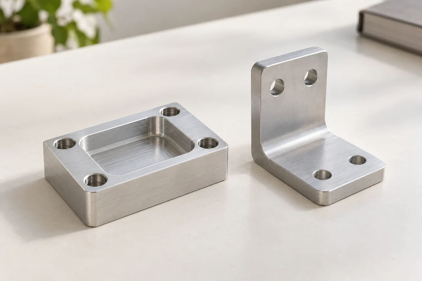
알루미늄 정밀가공의 소재 선택은 부품이 견뎌야 할 하중과 허용되는 움직임에서 시작합니다. 같은 브래킷도 파손 방지가 목적일 때와 센서의 위치 유지가 목적일 때 필요한 특성이 다릅니다. 여기에 습기, 접촉 재료, 표면처리와 반복 조립 조건을 더해야 합금의 장단점이 실제 기능으로 연결됩니다.
합금 계열과 강화 원리
6061은 주로 마그네슘과 실리콘을 이용하는 6xxx계, 7075는 아연·마그네슘·구리를 이용하는 7xxx계 열처리형 합금입니다. 용체화·급랭·시효를 거치면서 형성되는 미세 석출물이 전위의 이동을 방해해 강도를 높입니다. 따라서 합금 번호만 같아도 시효 상태가 다르면 기계적 성질이 달라집니다.
6061은 내식성·용접성·표면 마감과 일반 구조용 강도의 균형을 검토할 때 유용한 후보입니다. 7075는 크기나 단면을 늘리기 어려운 고하중 부품에서 높은 항복강도를 활용할 수 있습니다. 어느 쪽이든 형상, 열처리 상태와 사용 환경을 확인한 뒤 선정해야 합니다.
| 우선 해결할 요구 | 검토 방향 | 함께 확인할 조건 |
|---|---|---|
| 탄성 처짐과 위치 안정성 | 탄성계수와 단면 형상 | 지지 간격·리브·체결부 유연성 |
| 높은 하중에서 영구변형 방지 | 항복강도와 설계 여유 | 노치·응력 집중·소재 방향 |
| 용접 구조와 일반 내식성 | 6061 적용성 검토 | 열영향부 강도·용접 후 변형 |
| 좁은 공간의 고강도 구조 | 7075 적용성 검토 | 템퍼·부식 환경·접합 방법 |
설계 초기에는 합금 후보를 넓게 비교하되, 제작 도면에는 승인된 재질과 템퍼를 명확히 적습니다. “동급 알루미늄으로 대체” 같은 지시는 성능·후처리·검사의 기준을 흐리게 만듭니다. 대체가 필요하면 달라지는 물성과 공정 영향을 검토하고 승인 이력을 남기는 편이 재제작에도 유리합니다.
T6·T651·T7351과 소재 형태
템퍼는 단순한 경도 등급이 아니라 소재가 거친 열처리와 가공 이력을 나타냅니다. T6는 용체화 처리 후 인공시효한 상태를 뜻합니다. T651은 여기에 규정된 인장 방식의 응력완화가 포함된 상태이므로, 정밀 절삭에서 T6와 같은 의미로 생략해서는 안 됩니다.
7075의 T73 계열은 최대 강도에만 초점을 맞추기보다 응력부식균열 저항성을 고려한 시효 상태입니다. T7351은 해당 시효 상태와 인장 응력완화를 함께 나타냅니다. 압출재에서 만나는 T6511 등은 제품 형태와 추가 가공 조건까지 연결되므로 구매 규격에서 정확한 표기를 확인합니다.
| 표기·조건 | 실무에서 확인할 의미 |
|---|---|
| T6 | 용체화·인공시효 상태. 별도 응력완화 여부를 임의 추정하지 않습니다. |
| T651 | 인장 응력완화가 포함된 상태. 잔류응력이 완전히 사라진다는 뜻은 아닙니다. |
| 7075-T73 / T7351 | 강도와 응력부식균열 저항의 균형을 검토합니다. T7351은 인장 응력완화도 포함합니다. |
| 판재·봉재·압출재 | 제품 규격, 두께·단면, 시험 방향과 성적서를 함께 확인합니다. |
도면과 구매 명세의 연결
판재의 압연 방향과 두께 방향은 서로 다른 재료 방향입니다. 고하중 연결부나 깊게 파낸 블록은 최종 하중 방향이 원소재의 어느 방향과 대응하는지 검토할 필요가 있습니다. 봉재 자료의 대표값을 두꺼운 판재의 모든 방향에 그대로 적용하는 방식은 피합니다.
구매 단계에서는 합금·템퍼·제품 형태·적용 규격·성적서 요구를 하나의 조건으로 정리합니다. 소재를 절단한 뒤에도 로트와 식별 정보가 부품에 연결되도록 관리합니다. 강도가 중요한 부품이라면 납품 시 재질명만 확인하는 것보다 가공 전 추적성을 확보하는 편이 확실합니다.
02강도·강성·사용 환경
대표 물성 비교와 강도·강성의 차이
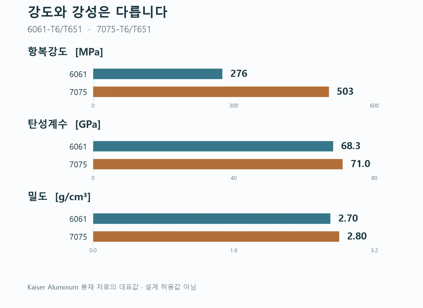
아래 수치는 Kaiser Aluminum의 공개 봉재 자료에 제시된 대표값을 비교한 것입니다. 6061-T6/T651과 7075-T6/T651 조건을 함께 표시했습니다. 최소 보증값이나 설계 허용값은 아니며, 실제 판정에는 적용 규격·제품 치수·시험 방향·소재 성적서가 우선합니다.
| 항목 | 6061-T6 / T651 | 7075-T6 / T651 |
|---|---|---|
| 인장강도 | 310 MPa | 572 MPa |
| 항복강도 | 276 MPa | 503 MPa |
| 탄성계수 E | 68.3 GPa | 71.0 GPa |
| 밀도, 약 20°C | 2.70 g/cm³ | 2.80 g/cm³ |
| 열전도율, 약 20°C | 167 W/(m·K) | 130 W/(m·K) |
| 선팽창계수, 20–100°C | 23.6 µm/(m·K) | 23.4 µm/(m·K) |
항복에 대한 여유와 탄성 처짐
표의 항복강도 비는 약 1.82이지만, 탄성계수 비는 약 1.04입니다. 같은 형상·지지·하중의 보가 선형 탄성 영역에서 휘는 단순 모델이라면 처짐은 E에 반비례합니다. 이 조건에서 6061을 7075로 바꿨을 때 계산되는 처짐 감소는 약 3.8%이며, 항복강도의 증가율과는 크게 다릅니다.
직사각형 단면의 굽힘 강성은 E와 단면2차모멘트 I의 곱으로 결정되며, I = bh³/12입니다. 폭 b가 같고 굽힘 방향의 두께 h를 10% 늘리면 I는 약 33% 증가합니다. 공간·질량 제약이 허용한다면 합금 변경과 함께 리브, 지지 간격, 하중 경로를 조정하는 방법을 검토할 이유입니다.
같은 부피라면 위 대표 밀도 기준으로 7075가 약 3.7% 무겁습니다. 고강도 소재로 단면을 줄여 경량화하려면 처짐, 국부 좌굴, 피로와 체결부까지 다시 계산해야 합니다. 높은 항복강도가 얇아진 부품의 모든 기능을 자동으로 보완하지는 않습니다.
피로·응력부식과 사용 환경
정적인 항복 검토를 통과해도 반복 하중에서의 수명이 충분하다고 결론낼 수는 없습니다. 피로 성능은 응력 진폭과 평균응력, 반복 횟수뿐 아니라 구멍 주변의 응력 집중, 표면 흠집과 부식 상태의 영향을 받습니다. 두 합금의 인장강도 비를 부품의 피로수명 비로 바꾸어 설명하지 않습니다.
7075 템퍼와 응력부식균열
응력부식균열은 민감한 재료 상태, 지속 인장응력과 특정 부식 환경이 함께 작용하는 문제입니다. 7075에서는 T6 계열과 T73 계열의 차이를 사용 환경과 연결해 검토합니다. 대표 봉재 자료에서 T73/T7351의 항복강도는 434 MPa로 T6/T651의 503 MPa보다 낮지만, 응력부식균열 저항을 개선하는 선택지가 됩니다.
이 차이는 T73 계열이 모든 환경에서 부식되지 않는다는 뜻이 아닙니다. 응력이 걸리는 방향, 두께, 잔류응력과 표면 손상까지 함께 검토해야 합니다. 젖은 틈새나 염분이 남는 구조에서는 보호막의 유무만큼 배수·밀봉·조립 형상이 중요합니다.
| 사용 조건 | 설계·제작에서 검토할 항목 |
|---|---|
| 반복 하중 | 응력 범위·노치 형상·표면 손상·필요 수명 |
| 지속 인장과 습윤 환경 | 템퍼·소재 방향·응력부식·잔류응력 |
| 스테인리스 등 이종금속 접촉 | 전해질 유입·절연·접촉 면적 관계·코팅 손상 |
| 마모와 반복 분해 | 접촉 압력·마찰·인서트·교체 가능한 마모부 |
부식과 피로가 중요한 부품은 최종 표면 상태까지 포함해 검증 조건을 정합니다. 가공면 시험 결과를 코팅·조립이 끝난 부품의 수명으로 곧바로 환산하지 않습니다. 도면의 재질 지정과 사용 환경의 정의가 함께 있어야 소재 비교가 유효해집니다.
03열적 특성과 소재 변형
열전도와 열팽창이 만드는 치수 변화
방열 부품에는 강도 외에 열이 흐르는 경로를 살펴야 합니다. 앞의 대표값에서 6061-T6/T651의 열전도율은 7075-T6/T651보다 높지만, 실제 온도 상승은 단면·길이·접촉 열저항·냉각 조건에 함께 좌우됩니다. 합금만 바꿔 방열 성능이 같은 비율로 개선된다고 계산할 수는 없습니다.
균일한 팽창과 온도 구배
균일한 온도 변화에서 자유롭게 팽창하는 단순 모델은 ΔL = αLΔT로 계산합니다. 설명용으로 길이 100 mm, 온도 변화 10 K와 앞의 평균 선팽창계수를 적용하면 6061은 약 23.6 µm, 7075는 약 23.4 µm 늘어납니다. 두 합금의 차이보다 절대적인 열팽창량이 중요할 수 있음을 보여주는 예시입니다.
한쪽 면만 가열되면 평균 온도가 같아도 휨이 생길 수 있습니다. 또 다른 재료에 고정되어 팽창이 구속되면 열응력과 접합부 하중이 발생합니다. 광학 지지대, 센서 베이스나 정밀 지그는 소재 비교와 함께 열원 위치, 대칭성, 지지 방식과 열평형 시간을 검토합니다.
| 상황 | 확인할 변수 | 판단에 필요한 정보 |
|---|---|---|
| 방열판·열전달 베이스 | 열전도율·단면·접촉 상태 | 발열량·접촉 열저항·냉각 조건 |
| 정밀 위치 유지 | 온도 변화·온도 구배 | 작동 온도 분포·지지 구조 |
| 정밀 치수 측정 | 부품·측정기 온도 | 열평형·온도 보정·불확도 |
| 이종재료 조립 | 팽창계수 차이·구속 | 체결 방식·미끄럼 허용·접합부 하중 |
정밀 측정은 일반적으로 20°C 기준 치수와 연결하지만, 모든 작업을 정확히 20°C에서만 해야 한다는 뜻은 아닙니다. 측정 온도와 열팽창 보정, 온도 차이에 따른 불확도를 관리해야 한다는 의미입니다. 절삭 직후 따뜻한 부품과 충분히 안정된 부품을 같은 조건으로 비교하지 않도록 측정 절차를 정합니다.
원소재 잔류응력과 포켓 가공 후 변형
두꺼운 소재에서 한쪽 면을 깊게 제거하면 내부에 균형을 이루던 잔류응력이 재분배됩니다. 얇아진 바닥이나 벽은 이 변화에 더 민감하게 반응할 수 있습니다. 가공 중에는 평평해 보였던 부품이 클램프를 풀자 휘는 현상을 공구 오차만으로 설명하기 어려운 이유입니다.
서로 구분할 세 가지 원인
| 변형의 출발점 | 주요 원인 | 확인 방법 |
|---|---|---|
| 원소재 내부 | 소재 제조·급랭·응력완화 이력 | 소재 로트·제거 위치·가공 순서 비교 |
| 절삭 표면층 | 기계적·열적 작용으로 생기는 가공 유발 잔류응력 | 공구·절삭 조건·표면 상태·자유 상태 형상 비교 |
| 가공 중 고정 | 클램프 힘과 지지 위치에 따른 탄성변형 | 고정 전후·해제 후 동일 기준 측정 |
응력완화 소재는 위험을 줄이는 선택지이지만 변형이 없어지는 보증은 아닙니다. 양면의 제거량을 가능한 범위에서 균형 있게 배분하고, 황삭 후 기준을 다시 확인한 뒤 정삭하는 순서를 검토합니다. 최종 형상이 비대칭이라면 대칭 가공이라는 원칙보다 실제 강성이 남는 순서가 우선할 수 있습니다.
Weber 등의 2021년 연구는 AA7050-T7451 밀링에서 가공 유발 잔류응력과 변형의 관계를 분석했고, 불안정한 절삭 조건에서 변동이 커지는 결과를 보고했습니다. 이는 변형 원인을 검토하는 근거로 유용하지만, 6061·7075의 수치 예측이나 범용 절삭 조건으로 직접 옮길 결과는 아닙니다.
단순히 시간을 두고 방치하거나 임의의 온도로 가열하는 방법을 응력제거 공정으로 간주하지 않습니다. 추가 열처리는 기존 템퍼와 치수에 영향을 줄 수 있습니다. 필요하다면 소재 공급자와 열처리 담당자가 승인한 조건, 처리 후 물성 확인과 재검사 범위를 먼저 정합니다.
04절삭과 공정 고정
절삭 조건과 표면 건전성
6061과 7075 모두 공구·윤활·칩 배출 조건에 따라 절삭 결과가 달라집니다. 낮은 경도가 항상 우수한 표면을 뜻하지 않으며, 강도가 높은 합금이라고 무조건 느린 가공만 가능한 것도 아닙니다. 소재 상태와 형상에 맞춘 공구 선택, 안정적인 절삭 두께와 칩의 재절삭 방지가 중요합니다.
회전수보다 먼저 연결할 변수
절삭속도 vc, 공구 지름 D와 회전수 n의 관계는 n = 1000vc/(πD)입니다. vc를 m/min, D를 mm로 입력하면 n은 rpm이 됩니다. 밀링 이송속도는 vf = n·z·fz로 계산합니다. 여기서 z는 유효 날 수, fz는 날당 이송량(mm/날), vf는 이송속도(mm/min)입니다. 실제 칩 두께는 반경 방향 절입과 공구 경로에 따라서도 달라집니다.
| 관리 변수 | 문제가 생기는 경로 | 조정 시 함께 볼 항목 |
|---|---|---|
| 날끝·경사각·날홈 | 용착·문지름·칩 막힘 | 소재용 공구 형상·날끝 상태·윤활 |
| 돌출 길이·홀더 | 공구 처짐·진동·런아웃 | 도달 깊이·간섭·가장 짧은 유효 돌출 |
| 축·반경 절입 | 절삭력·발열·코너 부하 | 잔여 두께·경로의 접촉각 변화 |
| 이송과 칩 배출 | 과도한 부하 또는 문지름·재절삭 | 유효 날 수·칩 두께·절삭유 공급 |
Jomaa 등의 AA7075-T651 건식 직교절삭 연구는 구성인선과 금속간화합물 입자가 표면 형성에 영향을 주는 과정을 다뤘습니다. 이 시험은 특정 공구와 건식 조건의 결과이므로 실제 MCT 공정의 회전수·이송값으로 그대로 적용할 수 없습니다. 실무에서는 평균 거칠기 Ra와 함께 찢김, 눌림, 방향성 가공 흔적을 확인하는 근거로 활용합니다.
절삭 조건은 공구 제조사의 해당 소재 권장 범위에서 시작해 장비·홀더·고정 강성에 맞춰 검증합니다. 회전수만 올리거나 이송만 낮추는 조정은 원인을 가릴 수 있습니다. 칩 형태, 부하 변화, 표면과 실제 치수의 변화를 함께 기록해야 다음 공정에서도 재현할 수 있습니다.
고정·황삭·정삭의 공정 설계
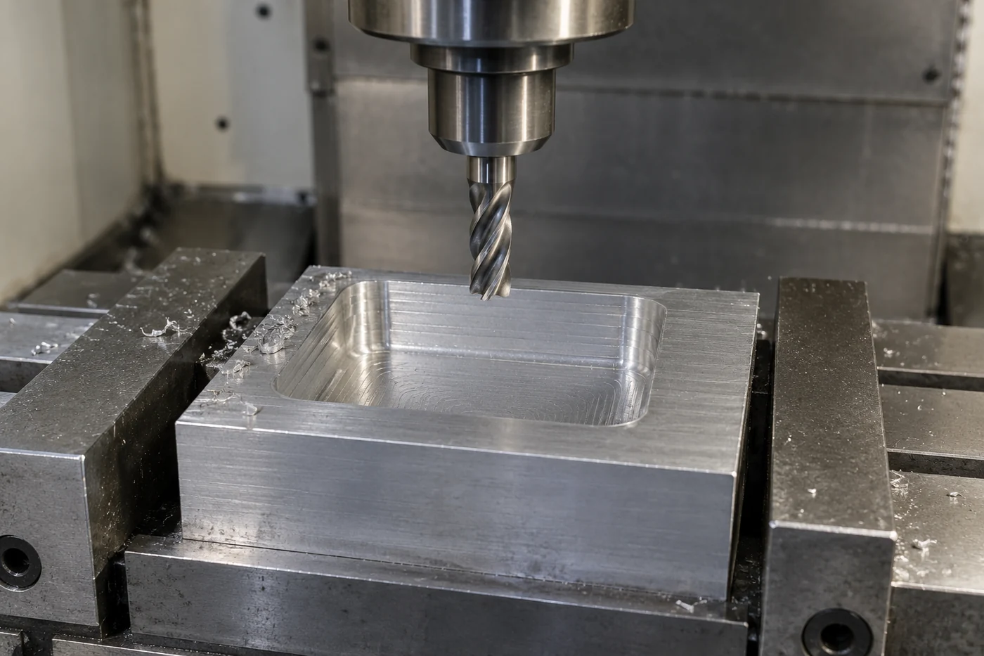
클램프는 절삭력을 견뎌야 하지만 얇은 부품의 형상을 누르거나 비틀 수도 있습니다. 특히 포켓 바닥과 긴 벽을 완성한 뒤에는 초기에 사용한 고정력이 과도해질 수 있습니다. 가공이 진행되면서 줄어드는 강성을 공정 단계별로 반영해야 합니다.
| 공정 단계 | 주요 목적 | 확인할 결과 |
|---|---|---|
| 소재·기준 준비 | 식별·방향 확인과 안정적인 기준 확보 | 절단 상태·안착·기준면 |
| 황삭 | 강성을 유지하며 주요 제거량 처리 | 정삭 여유·벽과 바닥의 남은 두께 |
| 해제·재안착 | 탄성 복원과 변형 확인 | 자유 상태 형상·새 기준의 타당성 |
| 정삭 | 안정된 조건에서 기능면 완성 | 기능 치수·면 관계·표면 상태 |
| 디버링·후처리·최종 검사 | 최종 사용 상태로 적합성 확인 | 모서리·끼워맞춤·코팅·청정도 |
고정 상태와 자유 상태의 구분
바이스에서 평탄도가 맞아도 풀어 놓은 상태의 평탄도가 같다고 볼 수는 없습니다. 반대로 사용 중 지정된 면에 체결되는 부품은 자유 상태 검사와 실제 구속 조건의 검사가 서로 다른 목적을 가집니다. 도면에서 어느 상태의 형상을 요구하는지 먼저 정하고 검사 지지를 맞춥니다.
정삭 여유가 지나치게 작으면 황삭에서 생긴 흔적이나 변형을 보정할 재료가 부족할 수 있습니다. 너무 크면 정삭 단계의 힘과 열이 증가합니다. 획일적인 여유값보다 부품 강성, 공구 형상과 공정 간 측정 결과를 근거로 결정합니다.
버 제거도 기능면을 만드는 공정입니다. 접촉면의 돌출 버는 안착을 방해하지만, 무리한 연마는 모서리 치수와 기준면을 손상시킬 수 있습니다. 버가 생기는 출구 방향을 줄이는 경로를 검토하고, 허용 모서리 상태와 제거 방법을 작업 기준에 남깁니다.
05기능 형상과 접합
포켓·구멍·나사의 기능 형상
가공성이 좋은 합금이라도 깊은 포켓, 작은 내부 코너와 얇은 벽이 겹치면 공정이 어려워집니다. 내부 코너 반경을 줄일수록 작은 공구와 긴 돌출이 필요해질 수 있습니다. 기능상 허용되는 반경과 벽 두께를 초기에 검토하면 진동·가공시간·표면 손상의 원인을 함께 줄일 수 있습니다.
구멍 치수와 위치의 서로 다른 역할
볼트 통과 구멍, 위치 결정 구멍과 베어링 안착부는 같은 “구멍”이어도 관리 목적이 다릅니다. 지름 공차만 엄격하게 지정하면 위치·축 방향·원통 형상이 필요한 기능을 놓칠 수 있습니다. 조립 기준을 먼저 정하고, 그 기준에서 필요한 형상과 위치 관계를 지정합니다.
| 형상 | 기능상 고려 | 제작·검사 관점 |
|---|---|---|
| 깊은 포켓·얇은 벽 | 강성·질량·간섭 | 공구 도달성·잔여 두께·고정 해제 변형 |
| 위치 결정 구멍 | 위치·방향·끼워맞춤 | 기준계·가공 순서·후처리 전후 치수 |
| 암나사·카운터보어 | 하중 전달·접촉 압력 | 완전산 물림·잔여 벽·좌면 버 |
| 내부 코너·단면 변화 | 응력 집중·피로 | 반경·공구 흔적·날카로운 단차 |
7075로 바꾸면 모재의 강도가 높아지지만, 나사 결합은 볼트 강도·유효 물림·주변 단면·예압과 마찰을 함께 검토해야 합니다. 얇은 벽이나 짧은 물림을 합금 변경만으로 해결했다고 판단하지 않습니다. 반복 분해가 많으면 인서트나 교체 가능한 체결 요소도 비교합니다.
나사 가공은 절삭 탭, 성형 탭과 나사 밀링의 차이를 형상·소재 상태에 맞춰 판단합니다. 막힌 구멍의 칩 공간, 공구 동기와 윤활, 입구 모따기는 최종 결합에 영향을 줍니다. 게이지 합격과 실제 조립 하중에 대한 적합성은 별도의 확인 항목입니다.
용접과 기계적 접합의 선택
용접이 포함된 구조라면 소재 선정 단계에서 접합 방법을 먼저 확인합니다. 6061은 일반적인 용융용접을 검토할 수 있는 합금이지만, T6 모재의 강도를 용접부와 열영향부에 그대로 적용하지 않습니다. 열 이력으로 석출 상태가 바뀌면서 국부적인 강도 저하와 변형이 발생할 수 있기 때문입니다.
7075는 일반적인 TIG·MIG 용접을 전제로 쉽게 대체할 소재가 아닙니다. 고강도 합금의 균열 민감성과 접합부 성능을 검토해야 하며, 특별한 접합 공정을 적용한다면 해당 절차와 성능 검증이 필요합니다. “알루미늄이므로 용접 가능”이라는 분류만으로 결정하지 않습니다.
접합 후 형상과 기능의 재검토
6061 용접 구조에서는 용가재, 용접 순서, 구속과 후속 가공을 함께 정합니다. 후열처리를 선택하더라도 전체 구조의 치수 변화와 접합부 특성을 검증해야 합니다. 용접 전에 완료한 정밀 구멍이나 기준면이 용접 후에도 요구 위치를 유지하는지 따로 확인합니다.
| 접합 선택 | 장점으로 검토할 점 | 추가 검토 |
|---|---|---|
| 6061 용접 구조 | 일체형 구조 구성 | 열영향부·용접 변형·후가공 기준 |
| 볼트·핀 결합 | 분해·교체·모듈화 | 미끄럼·접촉 압력·예압·위치 결정 |
| 7075 기계적 결합 | 고강도 모재 활용 | 나사·주변 단면·이종금속 부식 |
| 특수 접합 공정 | 설계 선택지 확장 | 공정 적합성·접합부 시험·승인 절차 |
기계적 접합에서도 나사와 위치 결정 기능을 구분하면 공차를 배분하기 쉽습니다. 체결력을 높여 미끄럼을 줄이는 방식은 접촉면 눌림이나 변형을 늘릴 수 있습니다. 모재 강도, 접촉 면적과 잠금 후 위치를 연결해 조립 조건을 정합니다.
06아노다이징과 표면 품질
아노다이징 피막과 최종 치수
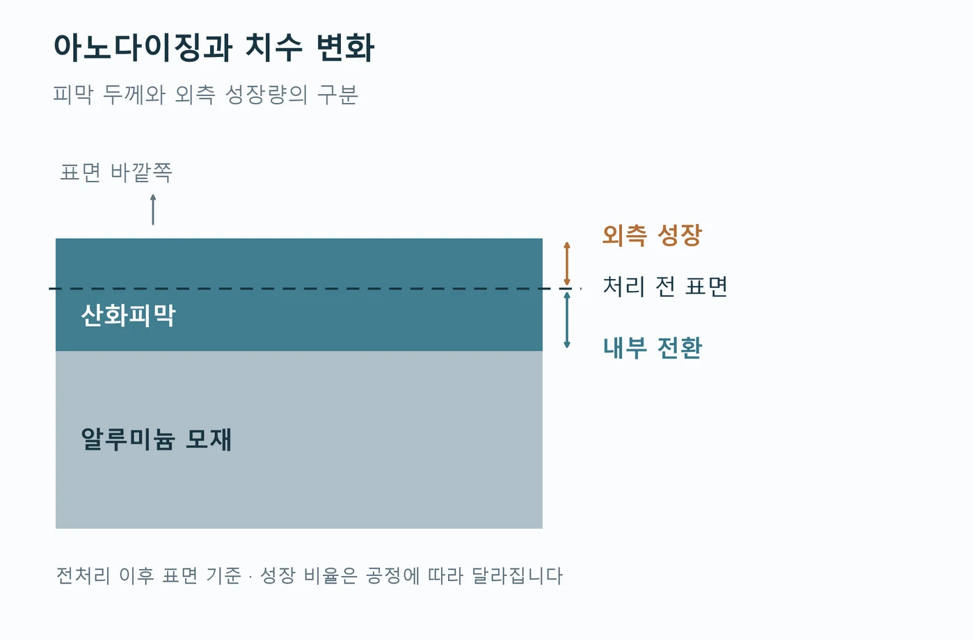
아노다이징은 알루미늄 표면을 산화피막으로 전환하는 처리입니다. 피막은 원래 금속 표면의 안쪽과 바깥쪽에 걸쳐 형성되므로, 전체 피막 두께를 그대로 외측 치수 증가량으로 더해서는 안 됩니다. 전처리에서 제거되는 양과 실제 외측 성장량을 구분해 가공 치수를 정합니다.
평면과 구멍의 치수 계산
전처리로 한 면에서 제거되는 양을 e, 남은 금속 표면에서 바깥으로 성장하는 양을 g라고 하면 단순 평면 모델의 순변화는 g − e입니다. 서로 마주 보는 두 외측 면이 같은 조건이라면 외형은 약 2(g − e) 증가하고, 구멍 지름은 약 2(g − e) 감소합니다. 이는 개념 계산이며 실제 보정값은 합금·공정·형상별 협의와 검증으로 정합니다.
| 기능 부위 | 처리 전 협의할 항목 | 최종 확인 |
|---|---|---|
| 정밀 구멍·핀 결합 | 성장량·전처리 제거·마스킹 | 후처리 후 지름·형상·조립성 |
| 암나사 | 피막 적용 범위·공정 순서 | 지정 게이지·체결 상태 |
| 접촉·접지 면 | 전도성 요구·마스킹 경계 | 접촉 상태·필요 전기적 성능 |
| 깊은 포켓·내측 면 | 피막 분포·측정 접근성 | 합의된 위치의 두께·외관 |
내부 구멍과 좁은 포켓의 피막이 외측 평면과 항상 같다고 가정하지 않습니다. NASA/JSC의 아노다이징 공정 문서도 내측 표면의 피막 차이와 최종 치수 지정의 중요성을 다룹니다. 특정 기관의 기본 두께를 일반 부품에 일괄 적용하기보다 도면과 사용 목적에 맞는 피막 조건을 정합니다.
후처리 후 나사를 다시 가공하거나 정밀면을 연마하면 그 부위의 피막이 제거될 수 있습니다. 치수를 복구하는 작업과 표면 보호를 유지하는 작업은 같은 결과가 아닙니다. 마스킹, 가공 순서와 최종 검사의 조합을 제작 전에 결정합니다.
표면 외관·경질 피막·마스킹
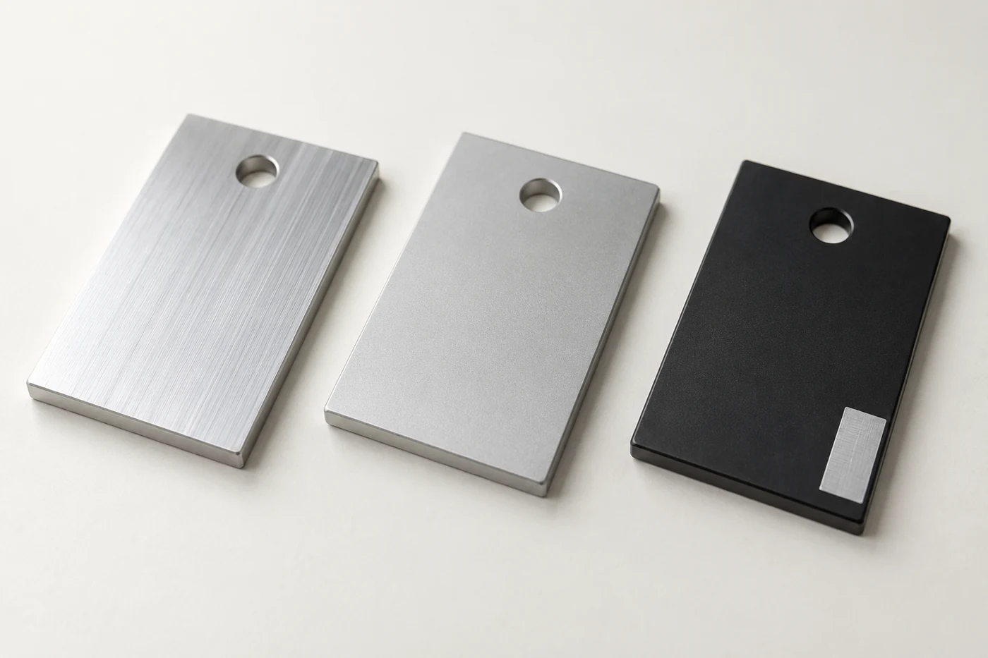
6061과 7075는 모두 아노다이징을 적용할 수 있지만 같은 공정에서 같은 색과 광택이 나온다고 보장할 수는 없습니다. 합금 성분, 소재 조직, 가공 흔적과 전처리가 외관에 영향을 줍니다. 사진의 은색이나 검은색만으로 합금, 피막 종류와 성능을 구별할 수 없습니다.
외관 요구와 기능 요구의 분리
일반 황산 아노다이징과 경질 아노다이징은 요구 성능에 따라 선택합니다. 내마모성이 필요하면 피막뿐 아니라 접촉 하중과 상대재, 윤활을 함께 검토합니다. 두꺼운 피막이 모재의 항복강도를 높여 주는 것은 아니므로 접촉부 아래의 알루미늄이 눌리는 문제는 별도로 검토합니다.
| 요구 | 명세에 포함할 내용 |
|---|---|
| 외관 균일성 | 색 기준·광택·가공 흔적 허용·비교 조명 |
| 내마모·내식 | 피막 종류·두께·실링·해당 성능 확인 |
| 전기적 접촉 | 마스킹 위치·접촉면 처리·접촉저항 요구 |
| 조립·끼워맞춤 | 최종 치수·마스킹 경계·검사 순서 |
| 랙 접촉 흔적 | 허용 위치·외관 면과 기능면의 구분 |
실링은 피막의 기공 상태와 내식 특성에 영향을 주며, 내마모나 접착 요구와 함께 선택해야 합니다. 색상 승인 시편도 합금·전처리·피막 조건이 실제 부품과 대응해야 의미가 있습니다. “검정 아노다이징” 한 줄에 외관·마찰·절연·내식 요구를 모두 맡기지 않습니다.
최종 외관은 밝고 일정한 조명에서 합의된 기준과 비교합니다. 기능면은 색상뿐 아니라 버, 손상, 마스킹 경계와 잔사를 살펴야 합니다. 청정도가 필요한 부품은 표면처리 이후의 헹굼·건조·취급·포장까지 연결해 관리합니다.
07검사와 문제 해결
소재 확인과 최종 품질검사
검사는 소재 입고, 가공 중, 후처리 후에 각각 다른 질문에 답합니다. 입고 검사는 지정된 소재를 사용했는지, 공정 검사는 변동을 제어하고 있는지, 최종 검사는 사용 상태의 요구를 만족하는지 확인합니다. 모든 검사를 마지막 치수 측정 한 번으로 대체하기는 어렵습니다.
재질명과 템퍼의 증거
소재 성적서와 로트 추적성을 기본으로 확보하고 필요하면 추가 식별 시험을 정합니다. 화학 성분 확인과 열처리 상태 확인은 같은 시험이 아닙니다. 경도나 전기전도도 결과도 시험 방법과 기준이 마련된 상태에서 보조 증거로 해석해야 하며, 값 하나로 모든 합금·템퍼를 확정하지 않습니다.
| 검사 단계 | 주요 항목 | 기록할 조건 |
|---|---|---|
| 입고 | 합금·템퍼·제품 형태·성적서 | 로트·절단 식별·도면 개정 |
| 가공 중 | 기준면·정삭 여유·변형·기능 치수 | 고정 상태·온도·공구 이력 |
| 후처리 후 | 최종 끼워맞춤·피막·마스킹·외관 | 측정 위치·공정 로트·검사 방법 |
| 조립 검증 | 안착·체결·위치·필요 성능 | 상대 부품·잠금 조건·사용 환경 |
평탄도·평행도·위치는 지름이나 두께와 다른 특성입니다. 기능 기준에 맞춘 지지와 측정점을 정하고, 필요하면 좌표측정이나 형상 측정을 사용합니다. 측정기의 분해능이 곧 측정 정확도인 것은 아니므로 반복성·교정·접촉력·온도와 측정불확도를 함께 검토합니다.
거칠기는 측정 방향과 평가 조건을 함께 기록합니다. 피막 두께 역시 곡면·모서리·작은 면적에서는 측정 방법의 적용성을 확인해야 합니다. 공차 경계 근처의 합격 판정은 불확도와 판정 규칙을 미리 합의해 두는 편이 재측정 분쟁을 줄입니다.
불량 현상별 원인 확인 순서
치수 불량이나 외관 문제를 합금 탓으로 바로 결론내리면 공정 원인을 놓칠 수 있습니다. 언제 처음 차이가 나타났는지, 고정 상태가 같았는지, 후처리 전후 결과가 어떻게 달라졌는지를 먼저 나눕니다. 한 번에 여러 조건을 바꾸기보다 의심 원인을 좁혀 비교하는 편이 재현성 확인에 유리합니다.
| 관찰된 현상 | 우선 의심할 경로 | 확인·대응 방향 |
|---|---|---|
| 클램프 해제 후 휨 | 고정 변형·잔류응력 재분배 | 자유 상태 측정·제거 순서·지지와 힘 비교 |
| 면의 찢김·문지른 흔적 | 날끝 용착·공구 상태·칩 재절삭 | 날끝 관찰·윤활·배출·절삭 두께 점검 |
| 주기적인 물결무늬 | 진동·런아웃·공구 또는 부품 유연성 | 홀더·돌출·고정·접촉각 확인 |
| 아노다이징 후 결합 불량 | 피막 성장·전처리·마스킹 조건 | 처리 전후 동일 부위 측정·보정 조건 확인 |
| 색상·광택 차이 | 합금·조직·전처리·공정 차이 | 소재와 공정 로트·승인 시편 비교 |
| 구멍 입구의 눌림·버 | 공구 출구·날끝 마모·디버링 | 확대 관찰·모서리 기준·가공 경로 검토 |
재가공 판단의 조건
재가공은 남은 치수 여유와 표면 상태를 함께 확인한 뒤 결정합니다. 치수만 맞추려고 코팅을 제거하거나 기준면을 바꾸면 다른 요구를 벗어날 수 있습니다. 원인, 수정 범위와 재검사 항목을 남겨야 동일한 문제가 반복될 때 비교할 수 있습니다.
표면 사진은 위치와 형태를 기록하는 데 유용하지만, 거칠기·피막 두께·치수의 측정값을 대신하지는 않습니다. 반대로 숫자만으로는 국부 흠집이나 버의 위치가 충분히 전달되지 않을 수 있습니다. 측정 결과와 확대 관찰을 기능 부위 기준으로 묶어 기록합니다.
08제작 비용과 소재 선정
소재 단가와 완성품 비용의 차이
6061과 7075의 견적은 kg당 소재 가격만으로 비교하기 어렵습니다. 필요한 규격의 재고, 최소 구매량, 절단 손실과 부품당 제거량이 소재비를 바꿉니다. 소량 제작에서는 CAM 준비·지그·세팅·검사·표면처리의 최소 비용이 개당 금액에 크게 반영될 수 있습니다.
동일한 납품 조건으로 비교할 항목
| 비용 요소 | 차이를 만드는 조건 | 비교 방법 |
|---|---|---|
| 소재 | 합금·템퍼·규격·구매 수량 | 동일 성적서·납품 조건으로 확인 |
| 준비·고정 | 설계 검토·CAM·지그·세팅 횟수 | 일회성 비용과 수량 연동 비용 분리 |
| 절삭 | 제거량·도달성·공구·공정 안정성 | 실제 경로와 예상 공정 시간 검토 |
| 후처리 | 피막·색·마스킹·최소 작업비 | 최종 치수와 검사 범위까지 일치 |
| 검사·품질 | 공차·성적서·추적성·조립 검증 | 필요 증거와 검사 빈도 명시 |
| 재작업 위험 | 변형·마감 불량·소재 대기 | 납기 여유와 재검사 비용 고려 |
공개 대표값으로 강도를 비교할 수는 있어도 현재 소재 가격이나 완성품 가격의 고정 배수는 정할 수 없습니다. 7075의 소재비가 더 높은 견적이어도 형상과 공정이 바뀌면 총비용 차이는 달라집니다. 반대로 설계에 필요 없는 고강도 소재를 선택하면 구매와 후처리 조건만 까다로워질 수 있습니다.
소량 부품의 원가를 줄이려면 먼저 불필요하게 좁은 공차, 작은 내부 반경과 깊은 가공부를 검토합니다. 기능면에 필요한 정밀도를 집중하고 비기능면은 합리적인 일반 요구로 정리합니다. 가공 업체가 치수를 임의 완화하는 방식이 아니라 설계 승인으로 요구를 명확히 하는 과정입니다.
용도별 판단과 제작 의뢰 조건
최종 선택은 “어느 합금이 더 좋은가”보다 부품이 만족해야 할 조건의 우선순위로 정리하는 편이 정확합니다. 강도 한계가 먼저인지, 처짐·열변형·부식·용접·표면 외관이 먼저인지 확인합니다. 그다음 소재와 공정을 함께 비교하면 필요 이상의 사양과 빠진 요구를 줄일 수 있습니다.
| 일반적인 검토 사례 | 우선 검토 방향 | 최종 선정 전에 확인 |
|---|---|---|
| 정밀 지그·센서 베이스 | 강성·열변형·기준면 중심으로 6061 검토 | 리브·지지 간격·작동 온도·평탄도 |
| 제한된 단면의 고하중 부품 | 7075의 항복강도 활용성 검토 | 템퍼·피로·부식·접합부 |
| 용접 프레임·일체 구조 | 6061과 접합 공정 동시 검토 | 열영향부·변형·후가공 |
| 외관·내식이 중요한 하우징 | 6061과 전처리·피막 조합 검토 | 승인 색상·마스킹·최종 조립 |
| 정밀 끼워맞춤이 있는 코팅 부품 | 합금과 피막의 치수 영향 동시 검토 | 처리 전 여유·처리 후 검사·마스킹 |
위 사례는 용도별 검토 방향이며 특정 설계의 적합성을 보증하는 선정표는 아닙니다. 실제 하중과 환경, 설계 여유와 검증 결과에 따라 선택이 달라집니다. 소재가 정해져 있다면 그 조건을 유지한 상태에서 형상·공정·검사 개선안을 협의합니다.
견적과 재제작에 필요한 전달 정보
제작 의뢰에는 도면과 3D 형상, 재질·템퍼·소재 형태, 기능 기준과 중요 공차, 표면처리·마스킹·최종 치수 조건을 함께 전달합니다. 이어서 수량·납기, 성적서와 추적성 요구, 상대 부품 또는 조립 검증 범위를 정리합니다. 자료가 부족한 항목은 제작자가 임의 추정하기보다 협의해 확정하는 편이 정확한 견적으로 이어집니다.
6061과 7075의 선택은 소재 번호에서 끝나지 않습니다. 하중과 변위의 검토가 가공 기준으로 이어지고, 고정과 절삭 조건이 표면처리 이후의 최종 검사로 연결되어야 합니다. 이 연결을 명확히 정리할수록 소량 정밀부품도 재제작과 설계 변경에 일관된 기준을 유지할 수 있습니다.
English Edition · 6061 and 7075 Precision Machining
In precision aluminum machining, choosing between 6061 and 7075 involves more than a single strength figure. Load capacity, elastic deflection in service, distortion after machining and dimensions after surface treatment are different criteria.
Using the balanced characteristics of 6061 or the high strength of 7075 effectively requires consideration of alloy, temper, geometry and process together. Public typical properties and engineering calculations connect material selection with cutting, anodizing, inspection and small-batch manufacturing cost.
Strength and stiffness
The higher yield strength of 7075 does not produce a proportional reduction in elastic deflection.
Temper through final dimensions
Manage temper, residual stress, workholding and coating growth as connected manufacturing conditions.
Finished-part cost
Compare stock, preparation, machining, finishing and inspection under the actual delivery requirements.
01Alloys and tempers
Material selection for precision aluminum machining
Material selection for precision aluminum machining begins with the load a part must withstand and the movement it can tolerate. The same bracket demands different properties when the priority is preventing failure or maintaining sensor position. Moisture, mating materials, surface treatment and repeated assembly must also enter the decision to connect alloy properties with actual function.
Alloy families and strengthening
6061 is a heat-treatable 6xxx alloy based primarily on magnesium and silicon. 7075 belongs to the heat-treatable 7xxx family and uses zinc, magnesium and copper. Fine precipitates formed through solution treatment, quenching and aging obstruct dislocation motion and increase strength. Consequently, identical alloy numbers can describe materials with different mechanical properties when their aging conditions differ.
6061 is a useful candidate when balancing corrosion resistance, weldability, finish and general structural strength. The high yield strength of 7075 can be valuable in highly loaded components whose size or section cannot readily increase. Either choice requires confirmation of geometry, temper and service environment.
| Priority | Evaluation route | Conditions to check |
|---|---|---|
| Elastic deflection and positional stability | Elastic modulus and section geometry | Support span, ribs and joint compliance |
| Prevention of permanent deformation under load | Yield strength and design margin | Notches, stress concentrations and material direction |
| Welded structures and general corrosion resistance | Evaluate 6061 | Heat-affected-zone strength and weld distortion |
| High strength within limited space | Evaluate 7075 | Temper, corrosion environment and joining method |
Compare candidates broadly during initial design, but specify the approved alloy and temper on the manufacturing drawing. Instructions such as “substitute equivalent aluminum” leave performance, finishing and inspection criteria ambiguous. When substitution is necessary, reviewing the changed properties and process effects and recording approval also improves repeatability on future orders.
T6, T651, T7351 and stock form
A temper identifies thermal and mechanical processing history, rather than merely a hardness grade. T6 denotes solution heat treatment followed by artificial aging. T651 additionally identifies specified stress relief by stretching, so the suffix should not be omitted as though it were interchangeable with T6 in precision machining.
The T73 family for 7075 uses an aging condition that considers stress-corrosion-cracking resistance rather than maximizing strength alone. T7351 combines that aging condition with stress relief by stretching. Designations such as T6511, encountered in extrusions, also relate to product form and further processing conditions, so the purchasing specification must preserve the exact designation.
| Designation or condition | Practical interpretation |
|---|---|
| T6 | Solution-treated and artificially aged. Do not infer a separate stress-relief operation. |
| T651 | Includes stress relief by stretching. It does not mean that residual stress is zero. |
| 7075-T73 / T7351 | Evaluate the balance between strength and stress-corrosion-cracking resistance. T7351 also includes stretching stress relief. |
| Plate, bar and extrusion | Check product specification, thickness or section, test direction and certification together. |
Connecting drawings with purchasing requirements
Rolling and through-thickness directions are distinct material directions in plate. Highly loaded connections and deeply pocketed blocks may require consideration of how the final load aligns with the original stock. Typical bar properties should not be applied indiscriminately to every direction in thick plate.
Treat alloy, temper, product form, governing specification and certification requirements as one purchasing condition. Maintain the connection between each cut blank and its material lot. For strength-critical parts, establishing traceability before machining provides stronger evidence than checking only the material name at delivery.
02Strength, stiffness and service environment
Typical properties: strength versus stiffness
The following comparison uses typical values from Kaiser Aluminum public rod-and-bar data, with 6061-T6/T651 and 7075-T6/T651 explicitly identified. These are neither guaranteed minima nor design allowables. The applicable specification, product dimensions, test direction and material certificate govern actual acceptance.
| Property | 6061-T6 / T651 | 7075-T6 / T651 |
|---|---|---|
| Ultimate tensile strength | 310 MPa | 572 MPa |
| Yield strength | 276 MPa | 503 MPa |
| Elastic modulus E | 68.3 GPa | 71.0 GPa |
| Density, approximately 20°C | 2.70 g/cm³ | 2.80 g/cm³ |
| Thermal conductivity, approximately 20°C | 167 W/(m·K) | 130 W/(m·K) |
| Linear expansion coefficient, 20–100°C | 23.6 µm/(m·K) | 23.4 µm/(m·K) |
Yield margin and elastic deflection
The table gives a yield-strength ratio of about 1.82 but an elastic-modulus ratio of only about 1.04. In a simple beam model with identical geometry, supports and load, deflection in the linear elastic range is inversely proportional to E. Under these conditions, replacing 6061 with 7075 reduces calculated deflection by about 3.8%, very different from the increase in yield strength.
For a rectangular section, bending stiffness depends on the product of E and the second moment of area I, where I = bh³/12. At constant width b, increasing the thickness h in the bending direction by 10% raises I by approximately 33%. Where space and mass permit, this supports evaluating ribs, support spacing and load paths alongside alloy substitution.
At equal volume, the stated typical densities make 7075 about 3.7% heavier. Reducing section size to exploit higher strength requires reassessing deflection, local buckling, fatigue and joints. A higher yield strength does not automatically compensate for every functional consequence of a thinner component.
Fatigue, stress corrosion and service environment
Passing a static yield assessment does not establish adequate life under cyclic loading. Fatigue performance depends on stress amplitude, mean stress and cycle count, together with stress concentrations around holes, surface damage and corrosion. The tensile-strength ratio of the alloys should not be presented as a ratio of component fatigue lives.
7075 temper and stress-corrosion cracking
Stress-corrosion cracking involves the combination of a susceptible material condition, sustained tensile stress and a relevant corrosive environment. For 7075, the distinction between T6 and T73 should be evaluated against service exposure. Typical bar data give a yield strength of 434 MPa for T73/T7351 versus 503 MPa for T6/T651, while the former provides an option for improved stress-corrosion-cracking resistance.
This distinction does not make T73 immune to corrosion in every environment. Loading direction, thickness, residual stress and surface damage also require consideration. In assemblies that retain moisture or salts, drainage, sealing and joint geometry matter alongside the presence of a protective coating.
| Service condition | Design and manufacturing considerations |
|---|---|
| Cyclic loading | Stress range, notch geometry, surface damage and required life |
| Sustained tension and moisture | Temper, material direction, stress corrosion and residual stress |
| Contact with stainless steel or other dissimilar metals | Electrolyte access, isolation, contact-area relationship and coating damage |
| Wear and repeated disassembly | Contact pressure, friction, inserts and replaceable wear elements |
For corrosion- or fatigue-critical parts, define verification conditions that include the final surface state. Results from a machined specimen cannot directly establish the life of a coated and assembled component. Material comparisons become useful when the drawing designation is accompanied by a defined service environment.
03Thermal behavior and stock distortion
Thermal conduction, expansion and dimensional change
Heat-dissipating components require examination of the heat-flow path in addition to strength. The typical thermal conductivity listed for 6061-T6/T651 exceeds that for 7075-T6/T651, but actual temperature rise also depends on cross-section, length, contact thermal resistance and cooling. Changing alloy alone does not improve overall heat dissipation in the same proportion.
Uniform expansion and temperature gradients
For a freely expanding body under a uniform temperature change, a simple model gives ΔL = αLΔT. An illustrative length of 100 mm, temperature change of 10 K and the stated mean expansion coefficients produce about 23.6 µm for 6061 and 23.4 µm for 7075. The example shows that absolute thermal expansion can matter more than the difference between the alloys.
Heating only one face can create bending even when average temperature is unchanged. Restraining expansion through attachment to another material can instead generate thermal stress and joint loads. Optical supports, sensor bases and precision fixtures therefore require consideration of heat-source position, symmetry, support conditions and equilibration time alongside alloy selection.
| Situation | Variables | Information needed |
|---|---|---|
| Heat sink or heat-transfer base | Conductivity, section and contact condition | Heat input, contact thermal resistance and cooling |
| Precision positioning | Temperature change and gradient | Operating temperature distribution and supports |
| Dimensional measurement | Part and instrument temperature | Equilibration, correction and uncertainty |
| Dissimilar-material assembly | Expansion mismatch and restraint | Fastening, permitted sliding and joint load |
Precision dimensional measurement is generally related to dimensions at 20°C, which does not mean every operation must occur at exactly that temperature. Measurement temperature, thermal correction and the uncertainty caused by temperature differences must be controlled. Establish a procedure that avoids treating a warm, freshly machined part as equivalent to a thermally stabilized one.
Stock residual stress and distortion after pocketing
Deep removal from one side of thick stock redistributes residual stresses that were previously balanced internally. Thin floors and walls can respond more strongly to that redistribution. This is why a part that appears flat while clamped may distort on release for reasons that cannot be explained by tool error alone.
Three causes to distinguish
| Origin | Principal cause | Evaluation route |
|---|---|---|
| Inside the stock | Manufacturing, quenching and stress-relief history | Compare stock lot, removal location and operation order |
| Machined surface layer | Machining-induced residual stress from mechanical and thermal action | Compare tools, cutting conditions, surfaces and free-state geometry |
| Workholding | Elastic deformation from clamping force and support position | Measure with consistent references before clamping, while held and after release |
Stress-relieved stock can reduce risk but does not guarantee zero distortion. Consider balancing removal between faces where feasible and rechecking datums after roughing before finishing. For an asymmetric final shape, an operation order that preserves useful stiffness may take precedence over a general preference for symmetric removal.
A 2021 study by Weber and colleagues examined machining-induced residual stress and distortion in milling AA7050-T7451 and reported greater variation under an unstable cutting condition. This supports investigating the mechanisms of distortion, but does not provide direct numerical predictions or universal cutting conditions for 6061 or 7075.
Leaving a part to rest or heating it to an arbitrary temperature should not be treated as a qualified stress-relief process. Additional heat treatment can affect the existing temper and dimensions. If required, first establish conditions approved by the material supplier and heat-treatment provider, together with post-treatment property checks and reinspection.
04Cutting and workholding
Cutting conditions and surface integrity
Both 6061 and 7075 respond to tool selection, lubrication and chip evacuation. Lower hardness does not always produce a better surface, and higher strength does not automatically require slow machining. Tool selection matched to material condition and geometry, stable chip thickness and prevention of chip recutting are important.
Variables to connect before selecting spindle speed
Cutting speed vc, tool diameter D and spindle speed n are related by n = 1000vc/(πD). With vc in m/min and D in mm, n is in rpm. Milling feed is calculated as vf = n·z·fz, where z is the effective tooth count, fz is feed per tooth in mm/tooth and vf is feed in mm/min. Actual chip thickness also varies with radial engagement and toolpath.
| Control variable | Failure mechanism | Items to evaluate together |
|---|---|---|
| Edge, rake and flute | Adhesion, rubbing and chip packing | Material-specific geometry, edge condition and lubrication |
| Tool overhang and holder | Deflection, vibration and runout | Reach, interference and shortest practical overhang |
| Axial and radial engagement | Cutting force, heat and corner loading | Remaining section and changes in engagement angle |
| Feed and chip evacuation | Overload, rubbing or recutting | Effective tooth count, chip thickness and coolant delivery |
Jomaa and colleagues studied how built-up edge and intermetallic particles affect surface formation in dry orthogonal cutting of AA7075-T651. The experiment used specific tooling and dry conditions, so its settings cannot be transferred directly to an MCT milling process. It supports examining tearing, smearing and directional tool marks alongside average roughness Ra.
Start with the tool manufacturer’s recommendations for the material and validate them against the machine, holder and workholding stiffness. Raising spindle speed alone or lowering feed alone can obscure the cause of a problem. Record chip form, load changes, surface condition and dimensional response together to make the result repeatable.
Planning workholding, roughing and finishing
Clamps must resist cutting forces but can also press or twist thin parts out of shape. The clamping force used initially may become excessive after pocket floors and long walls are finished. Process planning must account for the reduction in stiffness as material is removed.
| Process stage | Purpose | Result to check |
|---|---|---|
| Stock and datum preparation | Establish identification, orientation and stable references | Cut condition, seating and datum faces |
| Roughing | Remove the main stock while preserving stiffness | Finishing allowance and remaining wall/floor thickness |
| Release and reseating | Check elastic recovery and distortion | Free-state geometry and validity of the revised setup |
| Finishing | Complete functional surfaces under stable conditions | Functional dimensions, surface relationships and finish |
| Deburring, treatment and final inspection | Verify conformity in the final use condition | Edges, fits, coating and cleanliness |
Clamped and free-state conditions
Flatness achieved in a vise does not establish the same flatness after release. Conversely, a part attached to specified mounting faces in service may need both free-state and restrained checks for different purposes. First define the required condition on the drawing, then match the inspection support to it.
An excessively small finishing allowance may leave insufficient material to correct roughing marks or distortion. An excessive allowance increases force and heat during finishing. Determine it from part stiffness, tool geometry and interstage measurements rather than applying a single allowance to every part.
Deburring also contributes to functional geometry. A protruding burr can prevent proper seating, while aggressive abrasion can damage edge dimensions and datum surfaces. Consider toolpaths that reduce exit-edge burr formation and document acceptable edge conditions and removal methods.
05Functional geometry and joining
Functional geometry of pockets, holes and threads
Even a machinable alloy becomes challenging when deep pockets, small internal corners and thin walls occur together. Smaller internal corner radii can demand smaller tools with longer overhang. Reviewing functionally acceptable radii and wall thickness early can reduce the causes of vibration, long cycle times and surface damage together.
Different roles of hole size and location
A bolt-clearance hole, locating hole and bearing seat serve different purposes despite all being holes. A tight diameter tolerance alone can miss functional requirements for location, axis direction or cylindrical form. Establish assembly datums first and specify the required geometric and positional relationships from those datums.
| Feature | Functional considerations | Manufacturing and inspection |
|---|---|---|
| Deep pockets and thin walls | Stiffness, mass and clearance | Tool access, remaining section and release distortion |
| Locating holes | Position, orientation and fit | Datum system, operation order and dimensions before/after treatment |
| Internal threads and counterbores | Load transfer and contact pressure | Full-thread engagement, surrounding wall and seat burrs |
| Internal corners and section transitions | Stress concentration and fatigue | Radii, tool marks and sharp steps |
Changing to 7075 increases parent-material strength, but threaded joints still require consideration of bolt strength, effective engagement, surrounding section, preload and friction. Alloy substitution alone should not be taken as a solution for thin walls or short engagement. Inserts and replaceable fastening elements are also worth comparing where frequent disassembly is expected.
Select among cutting taps, forming taps and thread milling according to geometry and material condition. Chip space in blind holes, tool synchronization, lubrication and entrance chamfers affect the final connection. Gauge acceptance and suitability for actual assembly loading are separate checks.
Selecting welded or mechanical joints
If a structure includes welding, identify the joining method during material selection. 6061 can be considered for conventional fusion welding, but T6 parent-metal strength should not be assigned unchanged to the weld and heat-affected zone. The thermal cycle can alter precipitation, causing local strength loss and distortion.
7075 is not a straightforward substitute when conventional TIG or MIG welding is assumed. Cracking susceptibility and joint performance must be considered, and specialized joining requires a qualified procedure and performance verification. Classification simply as “weldable aluminum” is insufficient.
Reassessing geometry and function after joining
For welded 6061 structures, determine filler selection, weld sequence, restraint and subsequent machining together. If post-weld heat treatment is selected, verify dimensional changes across the structure and the resulting joint properties. Separately confirm whether precision holes and datum faces completed before welding retain their required positions afterward.
| Joining option | Potential benefit | Additional evaluation |
|---|---|---|
| Welded 6061 structure | Integrated structural assembly | Heat-affected zone, distortion and machining references |
| Bolted and pinned assembly | Disassembly, replacement and modularity | Slip, contact pressure, preload and location |
| Mechanical joints in 7075 | Use of high-strength parent material | Threads, surrounding section and galvanic corrosion |
| Specialized joining | Broader design options | Process suitability, joint testing and approval |
Separating fastening from locating functions also makes tolerancing clearer in mechanical joints. Increasing clamping force to reduce slip can increase contact indentation or distortion. Set assembly conditions by connecting parent-material strength, contact area and position after tightening.
06Anodizing and surface quality
Anodizing and final dimensions
Anodizing converts the aluminum surface into an oxide layer. Because the layer extends both inward and outward relative to the original metal surface, its total thickness cannot simply be added as external dimensional growth. Set machining dimensions by distinguishing pretreatment removal from actual outward growth.
Dimension accounting for faces and holes
Let e be the material removed from one face during pretreatment and g the growth outward from the remaining metal surface. A simple planar model gives a net change of g − e. For two opposing faces treated equally, an outside dimension increases by about 2(g − e), while a hole diameter decreases by about 2(g − e). This is conceptual accounting; actual compensation requires agreement and validation for the alloy, process and geometry.
| Functional region | Agreement before treatment | Final verification |
|---|---|---|
| Precision bores and pin fits | Growth, pretreatment removal and masking | Diameter, form and assembly after treatment |
| Internal threads | Coating coverage and process order | Specified gauges and engagement |
| Contact or grounding faces | Conductivity requirements and masking boundaries | Contact condition and required electrical performance |
| Deep pockets and internal faces | Coating distribution and measurement access | Thickness and appearance at agreed locations |
Do not assume that coating inside bores and narrow pockets always matches an external flat face. NASA/JSC anodizing process documentation also addresses internal coating differences and the importance of specifying final dimensions. Rather than transferring an institution-specific default thickness to general components, define coating conditions for the drawing and intended use.
Recutting a thread or grinding a precision face after treatment can remove its coating. Restoring dimensions and preserving surface protection are different outcomes. Decide the combination of masking, operation order and final inspection before manufacture.
Appearance, hard coatings and masking
Both 6061 and 7075 can be anodized, but identical color and gloss are not guaranteed under the same process. Alloy composition, material structure, machining marks and pretreatment affect appearance. Silver or black appearance in a photograph cannot identify the alloy, coating type or performance.
Separating cosmetic and functional requirements
Choose conventional sulfuric or hard anodizing according to required performance. Where wear resistance matters, consider contact load, mating material and lubrication in addition to the coating. A thicker coating does not increase the substrate’s yield strength, so indentation of the underlying aluminum remains a separate concern.
| Requirement | Items to specify |
|---|---|
| Uniform appearance | Color reference, gloss, acceptable tool marks and comparison lighting |
| Wear and corrosion resistance | Coating type, thickness, sealing and relevant performance verification |
| Electrical contact | Masking location, contact-face treatment and resistance requirement |
| Assembly and fit | Final dimensions, masking boundaries and inspection sequence |
| Racking contact marks | Permitted locations and distinction between cosmetic and functional faces |
Sealing changes the pore condition and corrosion behavior of the coating and should be selected together with wear or adhesion requirements. A color approval sample is meaningful only when its alloy, pretreatment and coating condition correspond to the intended part. A single note stating “black anodize” cannot define appearance, friction, insulation and corrosion requirements together.
Compare final appearance with agreed references under consistent lighting. Inspect functional faces for burrs, damage, masking boundaries and residues, as well as color. Where cleanliness matters, connect surface treatment with subsequent rinsing, drying, handling and packaging.
07Inspection and troubleshooting
Material verification and final quality inspection
Incoming, in-process and post-treatment inspections answer different questions. Incoming inspection verifies the specified stock, process checks monitor variation, and final inspection verifies requirements in the use condition. A single final dimensional measurement cannot replace all three.
Evidence for alloy and temper
Establish material certification and lot traceability, then define additional identification tests if needed. Verifying chemistry is different from verifying heat-treatment condition. Hardness or electrical-conductivity measurements should be interpreted as supporting evidence under defined methods and acceptance criteria; a single reading cannot identify every alloy and temper conclusively.
| Stage | Principal checks | Conditions to record |
|---|---|---|
| Incoming | Alloy, temper, product form and certification | Lot, blank identification and drawing revision |
| In-process | Datums, allowance, distortion and functional dimensions | Clamping state, temperature and tool history |
| After treatment | Final fits, coating, masking and appearance | Measurement locations, process lot and method |
| Assembly validation | Seating, fastening, position and required performance | Mating parts, tightening conditions and environment |
Flatness, parallelism and position are different characteristics from diameter or thickness. Define support and measurement points from the functional datum system and use coordinate or form measurement where needed. Instrument resolution is not measurement accuracy; consider repeatability, calibration, contact force, temperature and measurement uncertainty together.
Record measurement direction and evaluation conditions for roughness. For coating thickness, check method suitability on curved surfaces, edges and small areas. Agreeing uncertainty treatment and acceptance rules in advance reduces disputes when results fall close to tolerance limits.
A diagnostic sequence for common defects
Immediately blaming the alloy for a dimensional or cosmetic defect can hide its process origin. First identify when the difference appeared, whether clamping conditions matched and how results changed through surface treatment. Narrowing the suspected cause and making controlled comparisons is more useful for reproducibility than changing many variables simultaneously.
| Observed symptom | First mechanisms to consider | Evaluation and response |
|---|---|---|
| Warping after unclamping | Clamping deformation or residual-stress redistribution | Free-state measurement, removal sequence and support/force comparison |
| Tearing or smeared faces | Built-up edge, tool condition or chip recutting | Inspect edges, lubrication, evacuation and chip thickness |
| Periodic surface waves | Vibration, runout or tool/part flexibility | Check holder, overhang, clamping and engagement |
| Poor fit after anodizing | Growth, pretreatment or masking conditions | Measure identical features before/after treatment and check compensation |
| Color or gloss differences | Alloy, structure, pretreatment or process variation | Compare stock/process lots and approved samples |
| Burrs or rolled edges around holes | Tool exit, edge wear or deburring | Magnified inspection, edge criteria and toolpath review |
Conditions for rework decisions
Decide on rework after checking remaining dimensional allowance and surface condition together. Removing coating or changing a datum simply to recover size can violate another requirement. Record the cause, correction scope and reinspection items so repeated problems can be compared meaningfully.
Surface photographs help document location and appearance but do not replace measurements of roughness, coating thickness or dimensions. Conversely, numbers alone may not convey the position of local scratches or burrs. Link measurements and magnified observations to the relevant functional feature.
08Manufacturing cost and material selection
Material price versus finished-part cost
Quotations for 6061 and 7075 cannot be compared by stock price per kilogram alone. Availability in the required size, minimum purchase quantity, cutting loss and material removal per part affect stock cost. For small batches, CAM preparation, fixtures, setup, inspection and finishing minimum charges can have a substantial effect on unit cost.
Items to compare under identical delivery conditions
| Cost element | What changes it | Comparison method |
|---|---|---|
| Stock | Alloy, temper, size and purchase quantity | Match certification and delivery conditions |
| Preparation and workholding | Design review, CAM, fixtures and setup count | Separate one-time and quantity-dependent costs |
| Cutting | Removal volume, accessibility, tools and stability | Review actual toolpaths and estimated process time |
| Finishing | Coating, color, masking and minimum charges | Match final dimensions and inspection scope |
| Inspection and quality | Tolerances, reports, traceability and assembly validation | Specify required evidence and inspection frequency |
| Rework risk | Distortion, finish defects and stock lead time | Consider schedule margin and reinspection cost |
Public typical properties support strength comparisons but cannot establish current stock prices or a fixed finished-part price multiplier. Even when a quotation lists a higher material cost for 7075, changes in geometry and processing alter the total difference. Conversely, selecting high strength without a functional need can complicate purchasing and finishing conditions.
To reduce small-batch cost, first review unnecessarily tight tolerances, small internal radii and deep features. Concentrate precision on functional surfaces and use reasonable general requirements elsewhere. This means clarifying requirements through design approval, rather than allowing the manufacturer to relax dimensions unilaterally.
Application decisions and manufacturing inputs
A final choice is clearer when organized around the priority of requirements rather than asking which alloy is better overall. Determine whether strength, deflection, thermal movement, corrosion, welding or appearance is the first constraint. Comparing material and process together then reduces both unnecessary specifications and omitted requirements.
| Illustrative application | Initial evaluation | Checks before final selection |
|---|---|---|
| Precision fixture or sensor base | Evaluate 6061 around stiffness, thermal movement and datums | Ribs, support span, operating temperature and flatness |
| Highly loaded part with limited section | Evaluate use of 7075 yield strength | Temper, fatigue, corrosion and joints |
| Welded frame or integrated structure | Evaluate 6061 together with the joining process | Heat-affected zone, distortion and finish machining |
| Housing prioritizing appearance and corrosion resistance | Evaluate 6061 with pretreatment and coating | Approved color, masking and final assembly |
| Coated component with precision fits | Evaluate alloy and coating dimensional effects together | Machining allowance, post-treatment inspection and masking |
These examples indicate evaluation routes, not guaranteed material selections for a specific design. Actual loading, environment, design margin and verification results can change the choice. If a material is already specified, discuss improvements to geometry, processing and inspection while preserving that requirement.
Inputs for quotation and repeat manufacture
Provide the drawing and 3D geometry together with alloy, temper, stock form, functional datums, critical tolerances, surface treatment, masking and final dimensional requirements. Then define quantity, delivery date, reporting and traceability requirements, and mating-part or assembly-validation scope. Resolve missing inputs through discussion rather than leaving the manufacturer to infer them, so the quotation reflects the actual job.
Selecting 6061 or 7075 does not end with an alloy number. Load and displacement requirements must inform machining references, while workholding and cutting conditions must connect to final inspection after treatment. Making those connections explicit gives even small-batch precision parts a consistent basis for repeat manufacture and design changes.
추가 정보
검색엔진용 요약
알루미늄 정밀가공에서 6061과 7075는 강도뿐 아니라 템퍼·탄성계수·열적 특성·부식 환경·가공 변형·표면처리 조건을 함께 비교해야 합니다. 대표 물성과 설계 허용값을 구분하고, 최종 치수와 검사·추적성·소량 제작 비용을 연결해 소재와 공정을 선정합니다.
핵심 포인트 정리
- 높은 항복강도와 높은 굽힘 강성은 같은 의미가 아니며, 형상과 지지 조건을 함께 검토합니다.
- T6·T651·T7351 표기와 판재·봉재·압출재 조건을 구매 명세에 정확히 연결합니다.
- 응력완화 소재도 가공·고정·잔류응력 재분배에 의해 변형될 수 있습니다.
- 절삭 조건은 회전수뿐 아니라 날끝·칩 두께·돌출·접촉각·칩 배출을 함께 관리합니다.
- 아노다이징 피막 전체 두께와 외측 성장량을 구분하고 최종 끼워맞춤을 검사합니다.
- 소재 성적서·로트와 후처리 이력을 유지하고 단품 치수와 조립 기능을 구분해 검증합니다.
- 소량 제작 비용은 소재 가격에 준비·세팅·절삭·후처리·검사와 재작업 위험을 더해 비교합니다.
FAQ
7075로 바꾸면 같은 부품이 훨씬 덜 휘나요?
항복강도와 탄성계수는 다른 특성입니다. 제시한 대표값의 탄성계수 차이는 약 4%이므로 같은 형상·하중·지지의 선형 탄성 보 모델에서는 처짐 감소가 약 3.8%입니다. 강성 개선에는 리브·두께·지지 간격도 함께 검토합니다.
T6와 T651은 무엇이 다른가요?
T6는 용체화 처리 후 인공시효 상태를 나타내며, T651은 규정된 인장 응력완화가 포함됩니다. T651을 잔류응력이 전혀 없는 상태로 해석해서는 안 됩니다. 제품 형태와 성적서도 함께 확인합니다.
6061과 7075의 대표 강도를 설계값으로 써도 되나요?
공개 대표값은 초기 비교에 유용하지만 최소 보증값이나 설계 허용값은 아닙니다. 실제 설계와 납품 판정은 적용 규격·템퍼·치수·시험 방향·소재 성적서와 필요한 설계 기준을 따릅니다.
7075의 T73 계열을 선택하는 이유는 무엇인가요?
T6 계열 대비 강도와 응력부식균열 저항의 균형을 검토하기 위한 선택지입니다. 사용 환경·지속 응력·소재 방향과 두께를 함께 확인하며, 모든 환경에서 부식되지 않는다는 의미는 아닙니다.
아노다이징을 하면 구멍 치수가 바뀌나요?
피막 성장과 전처리의 금속 제거에 따라 최종 지름이 달라질 수 있습니다. 전체 피막 두께를 그대로 지름 변화로 적용하지 않고, 양쪽 면의 순변화와 실제 공정 조건을 확인합니다. 최종 상태에서 검사해야 합니다.
표면 색으로 6061과 7075를 구별할 수 있나요?
외관만으로 합금이나 템퍼를 확정할 수 없습니다. 소재 성적서와 로트 추적성을 우선 확인하고, 필요하면 적합한 식별 시험을 추가합니다. 가공·전처리·피막도 외관을 바꿉니다.
소량 제작에서 무엇이 비용을 크게 좌우하나요?
소재 규격과 최소 구매량 외에 CAM·지그·세팅·정밀 검사·표면처리 최소 비용이 개당 금액에 반영됩니다. 동일한 최종 치수, 후처리와 검사 조건으로 견적을 비교해야 합니다.
관련 주제 확장 설명
형상 설계와 강성
같은 합금에서도 단면2차모멘트와 지지 간격이 처짐을 크게 바꿉니다. 소재 변경 전에 기능상 허용되는 리브와 두께, 체결부의 유연성을 검토하면 강도와 위치 안정성을 구분해 개선할 수 있습니다.
공정 간 변형과 최종 검사
가공 중 구속된 상태와 자유 상태의 형상은 다를 수 있습니다. 황삭·재안착·정삭·후처리 단계에서 기준과 측정 조건을 일관되게 관리해야 변형이 발생한 구간을 찾을 수 있습니다.
표면처리와 조립 기능
피막 종류·마스킹·실링과 공정 순서는 치수뿐 아니라 접촉·마찰·전도성에도 연결됩니다. 외관 요구와 기능 요구를 나누고 최종 상태에서 확인할 특성을 명세에 포함합니다.
내부 링크
기능에 맞는 공차는 CNC 공차와 정밀도에서, 표면 평가 조건은 표면거칠기와 측정 기준에서 확인할 수 있습니다. 후공정은 정밀부품 세척과 청정도와 연결해 검토합니다.
지지 구조의 설계와 제작은 플레이트·브래킷 가공, 제작 방식은 정밀 CNC 가공을 참고할 수 있습니다. 소재·형상·후처리와 검사 범위의 협의는 제품문의·개발의뢰를 통해 진행할 수 있습니다.