정밀 금속부품 세척과 청정도:
치수가 맞아도 불량이 되는 이유
정밀 금속부품 세척과 청정도 관리는 치수 검사만으로 잡기 어려운 조립·기능 불량을 줄이는 과정입니다. 작은 칩 하나가 유로를 막고, 눈에 잘 보이지 않는 가공유가 접착과 표면처리를 방해할 수 있습니다. 반짝이는 외관만으로 납품 적합성을 판단하기 어려운 이유입니다.
세척의 목표는 기능에 필요한 잔류물 기준을, 합의한 검사법과 인도 상태에서 만족하는 것입니다. 오염을 떼어내는 조건에 더해 헹굼·건조·취급·포장을 관리하고, 입자와 표면막은 각각 맞는 방법으로 확인해야 합니다.
오염별 기준
입자·유막·이온성 잔류물을 구분하고 기능면의 위험을 먼저 정합니다.
형상별 공정
액 접근·교환·배출이 되는지 확인하고 적재와 건조까지 함께 설계합니다.
검사와 인도 상태
추출 검증·공시험·분석 조건을 맞추고 포장 후의 합격 시점을 합의합니다.
01기능 요구와 오염원
기능과 청정도
정밀부품은 치수가 공차 안에 들어와도 잔류 오염 때문에 제 기능을 하지 못할 수 있습니다. 청정도는 표면의 광택보다, 남아 있는 물질이 조립과 사용에 어떤 영향을 주는지를 기준으로 판단해야 합니다.
입자·막·이온의 구분
칩과 연마 입자는 좁은 유로를 막거나 움직이는 접촉면에 끼어 손상을 일으킬 수 있습니다. 같은 크기의 입자라도 부품의 간극, 입자의 재질과 형상, 이동 가능한 경로에 따라 위험이 달라집니다.
| 오염 유형 | 대표 잔류물 | 기능상 검토 대상 |
|---|---|---|
| 입자 | 금속 칩, 연마재, 섬유 | 유로 막힘, 접촉면 손상, 조립 중 이동 |
| 막 형태 잔류물 | 가공유, 그리스, 방청제 | 접착·도장·코팅 전 표면 상태 |
| 이온성 잔류물 | 염류와 공정 약품의 일부 성분 | 수분이 존재하는 조건의 부식, 전기 부품의 누설 전류 위험 |
이 세 유형은 서로 완전히 분리된 범주가 아닙니다. 기름막에 입자가 붙어 있거나, 마른 자국에 이온성 성분이 남을 수 있으므로 한 가지 오염만 제거했다고 전체 청정도가 확보되지는 않습니다.
기능면과 공급 상태
세척 목표는 다음 공정과 연결해 정해야 합니다. 보관 중 부식을 막기 위해 남기는 방청막도 접착이나 코팅 직전에는 제거 대상이 될 수 있으므로, 유지할 표면 처리와 제거할 오염을 구분해야 합니다.
외관이 보이는 바깥 면뿐 아니라 밀봉면, 조립 접촉면, 내부 유로를 먼저 살펴보는 것이 좋습니다. 오염이 실제로 이동하거나 접촉할 수 있는 영역을 정리해야 세척 범위를 기능 위험에 맞출 수 있습니다.
오염 발생과 잔류 위치
최종 세척의 부담은 앞선 가공에서 들어오는 오염량에 크게 좌우됩니다. 절삭 칩, 연삭·연마 잔류물, 가공유를 공정별로 구분하면 약품 성능 문제와 오염 유입 문제를 더 정확하게 나눌 수 있습니다.
상류 공정의 오염원
부품에 붙어 있는 버와 이미 떨어진 금속 입자는 처리 관점이 다릅니다. 세척으로 느슨한 입자를 제거하더라도 교차 구멍의 버가 나중에 떨어지면 다시 오염원이 되므로, 버 제거 공정의 적절성도 함께 확인해야 합니다.
연마 후와 절삭 후의 부품을 같은 조건으로만 평가하면 실제 오염 차이를 놓치기 쉽습니다. 세척 시험에는 해당 공정의 가공유와 잔류물을 가진 부품을 사용하고, 시험 전 임의로 닦아 실제 유입 상태를 바꾸지 않아야 합니다.
교차 구멍과 막힌 구멍
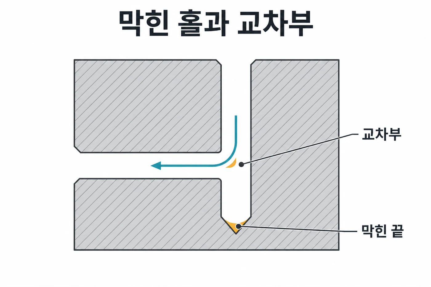
막힌 구멍과 내부 교차부는 세척액이 들어가는 것만으로 충분하지 않습니다. 갇힌 공기를 내보내고 오염된 액을 새 액으로 교체한 뒤 배출할 수 있어야 하므로, 입구의 크기와 방향뿐 아니라 출구와 배액 자세를 함께 검토해야 합니다.
- 입구: 노즐 방향과 지그가 세척액 접근을 가리는지 확인합니다.
- 내부: 단차·교차부·막힌 끝에 칩이 머물거나 공기가 갇히는지 살펴봅니다.
- 출구: 분리된 입자와 오염액이 부품 밖으로 나갈 경로를 확인합니다.
아래 단면의 화살표는 세척액이 접근할 수 있는 연결 경로를, 주황색은 잔류 여부를 확인할 위치를 나타냅니다. 유로가 연결되어 있어도 막힌 끝까지 같은 액 교환이 보장되는 것은 아닙니다.
02세척 공정과 적재
세척액과 소재 적합성
세척액은 제거할 오염과 지켜야 할 소재를 함께 보고 선택해야 합니다. 수계와 유기용제계 중 어느 한쪽을 모든 정밀부품에 우선 적용하는 방식으로는 표면 손상과 잔류 문제를 충분히 다루기 어렵습니다.
오염과 세척액의 조합
수계 세척제에는 중성·알칼리성·산성 등 서로 다른 조성이 있으며, 같은 수계라도 탈지력과 소재 적합성이 다릅니다. 유기용제 역시 성질이 다양하므로 가공유가 잘 제거된다는 이유만으로 수용성 잔류물까지 제거된다고 판단해서는 안 됩니다.
| 세척액 계열 | 선정 시 확인 사항 | 후속 공정 조건 |
|---|---|---|
| 수계 | 오염 종류, 세척제 조성, 합금·표면 처리의 내약품성 | 약품 잔류를 줄이는 헹굼과 배액·건조 경로 |
| 유기용제계 | 오염물의 용해 특성, 소재·수지·씰과의 적합성 | 선택한 용제에 맞는 설비, 회수와 건조 조건 |
온도·농도·시간을 높이면 항상 세척 결과가 좋아지는 것은 아닙니다. 오염 제거와 함께 변색, 표면 공격, 약품 잔류를 살펴보고 실제 소재와 오염을 사용한 시험으로 적용 범위를 정해야 합니다.
합금과 표면 처리의 확인
알루미늄·마그네슘·아연계 합금은 특히 약품 적합성을 확인할 필요가 있습니다. 예를 들어 알칼리성 제품인 Elma Clean 300도 이들 합금에는 사전 내약품성 시험을 요구하므로, 제품의 금속용 표기만으로 적용을 결정하기 어렵습니다.
도금·산화피막과 조립된 수지·씰이 있으면 모재만으로 적합성을 판단하지 않아야 합니다. 시험에서는 세척 직후의 외관뿐 아니라 보호해야 할 표면 상태가 유지되는지 확인하고, 제조사 권장 조건을 해당 부품의 검증 조건으로 구체화해야 합니다.
기계적 작용과 적재
적절한 약품도 필요한 표면에 도달하지 못하면 효과가 제한됩니다. 세척 방식은 오염을 떼어 내는 작용과 분리된 오염을 밖으로 운반하는 흐름을 함께 고려해 선택해야 합니다.
형상에 맞는 세척 작용
분사, 침적, 초음파와 감압을 활용하는 공정은 서로 다른 방식으로 세척을 돕습니다. 복잡한 부품에서는 여러 작용을 조합할 수 있지만, 특정 방식을 넣었다는 사실만으로 내부까지 세척되었다고 볼 수는 없습니다.
| 방식 | 주요 작용 | 형상·적재 검토점 |
|---|---|---|
| 분사 | 지향성 액류로 표면 세척 | 노즐 정렬, 지그와 부품 뒤의 분사 사각부 |
| 침적·유동 | 액에 담그고 흐름으로 오염 배출 보조 | 내부 공기 배출과 오염액 교체 경로 |
| 초음파 | 액 중 캐비테이션으로 오염 분리 보조 | 젖음 상태, 민감한 표면, 부품 겹침 |
| 감압·압력 변동 | 복잡한 내부 형상의 세척 보조 | 공정에 맞는 챔버와 액 접근·배출 조건 |
바스켓과 적재 자세
부품을 겹쳐 담으면 맞닿은 면의 액 접근이 줄고 아래쪽 부품에 오염이 다시 묻을 수 있습니다. 바스켓의 적재량뿐 아니라 부품 간격, 지지 위치, 구멍 방향을 정해 세척과 배액에 필요한 공간을 확보해야 합니다.
소량으로 흩어 놓은 시험품의 결과를 밀집된 양산 적재에 그대로 적용해서는 안 됩니다. 실제 적재 수량과 지그를 사용하고, 회전·요동이 필요하다면 부품 손상과 배액까지 함께 확인해야 합니다.
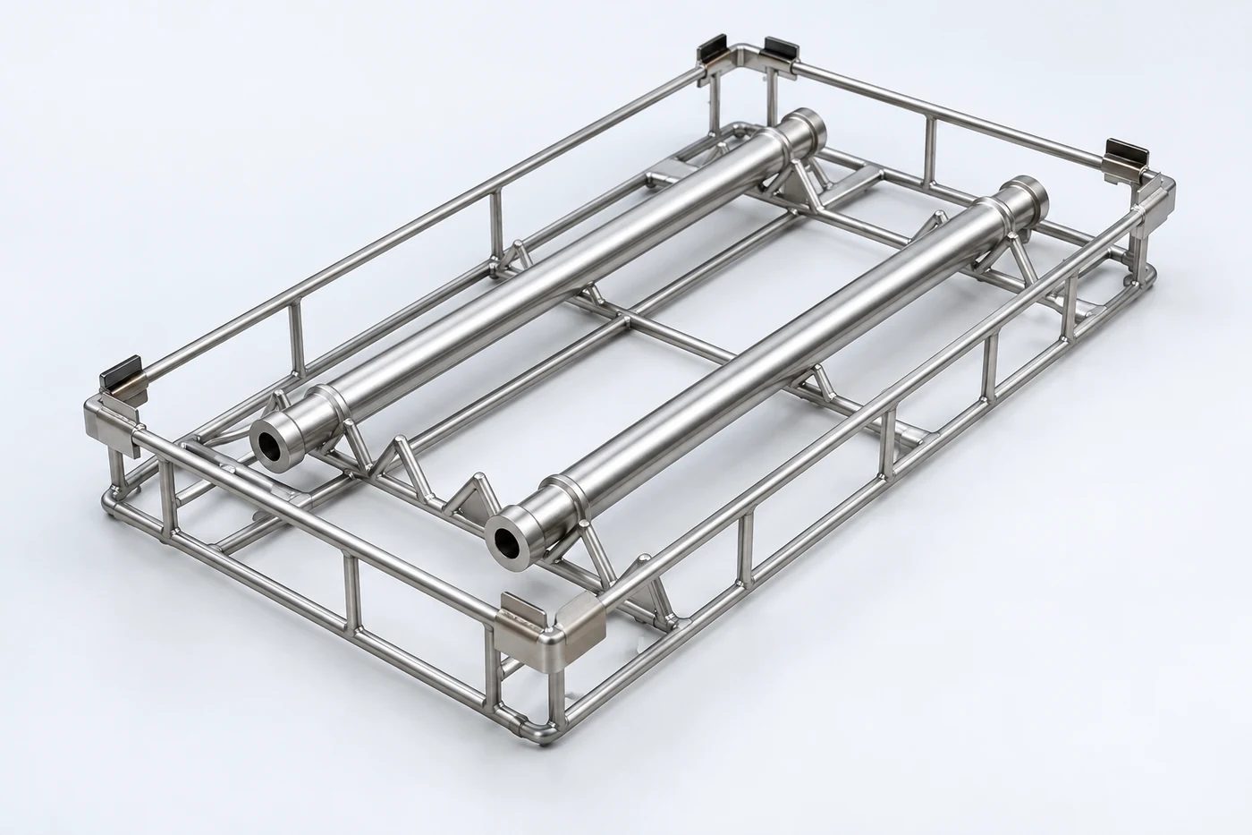
샤프트를 떨어뜨려 지지하는 개방형 캐리어는 부품 사이의 공간과 지지점을 함께 설계하는 사례입니다. 짧은 부싱이나 얇은 판재는 필요한 지지 방식이 다르므로, 실제 형상에 맞춰 접촉 자국과 배액을 확인해야 합니다.
03공정 유지와 재오염
세정욕과 헹굼 관리
부품에서 떨어진 오염은 세정욕으로 이동하므로, 사용 중인 액의 상태는 계속 달라집니다. 새 액으로 얻은 좋은 결과를 유지하려면 유입 오염량과 제거 능력, 약품 농도를 함께 관리해야 합니다.
오염 부하와 농도
입자용 필터만으로 유분이나 용해된 오염까지 모두 관리할 수는 없습니다. 필터는 유량과 차압, 포집 성능을 확인하고, 유분은 세척제의 유화·유분 분리 특성에 맞는 관리 방법을 별도로 검토해야 합니다.
농도는 처음 조제할 때만 맞추는 값이 아닙니다. 약품이 부품에 묻어 나가는 양과 보충 이력을 고려하고, 제조사가 해당 조성에 제시한 측정 방법으로 추세를 확인해야 농도 변화와 오염 축적을 혼동하지 않을 수 있습니다.
헹굼수와 잔류물
헹굼은 부품에 남은 세척액과 분리된 오염을 줄이는 공정입니다. 앞 단계의 액이 다음 탱크로 넘어가는 드래그아웃이 크면 헹굼수도 빠르게 오염되므로, 탱크 수뿐 아니라 배액과 물 교체 흐름을 함께 봐야 합니다.
헹굼수 전도도는 주로 물속 이온성 성분의 변화를 보는 관리 지표입니다. 전도도가 낮아도 비이온성 유기물이나 부품에 붙은 입자를 모두 설명하지 못하며, 탱크의 수질 결과가 곧 부품 표면의 합격 결과가 되지는 않습니다.
- 세정욕: 농도와 오염 부하의 추세를 함께 기록합니다.
- 순환 계통: 필터 상태, 유량, 노즐 막힘을 확인합니다.
- 헹굼: 유입수·사용수의 상태와 부품에서 넘어오는 액을 함께 관리합니다.
건조와 재오염
건조는 오염된 물을 증발시키는 것만으로 끝나지 않습니다. 배액과 헹굼이 부족하면 액 속 성분이 표면에 남을 수 있으므로, 건조 후 자국이 생겼을 때는 건조기와 앞선 공정을 함께 살펴봐야 합니다.
배액과 건조 경로
막힌 구멍과 오목한 면의 물고임은 부품 자세에 따라 달라집니다. 바깥 면이 말라도 내부에 액이 남을 수 있으므로, 자세 변경으로 배액을 돕고 형상에 맞춰 열풍·진공 건조 등의 적용을 검토해야 합니다.
세척 후 습윤 상태가 이어지면 소재와 잔류 성분에 따라 부식 문제가 생길 수 있습니다. 건조 지연, 내부 잔류액, 필요한 방청 조건을 함께 검토하되, 후속 접착이나 코팅에 영향을 주는 방청제를 임의로 추가해서는 안 됩니다.
취급과 보호 포장
에어 블로를 사용할 때는 압축공기 자체도 오염원인지 확인해야 합니다. 물·오일·입자는 압축기와 배관에서 유입될 수 있으므로, 오일프리 압축기라는 명칭만으로 부품에 닿는 공기의 청정도를 판단하기 어렵습니다.
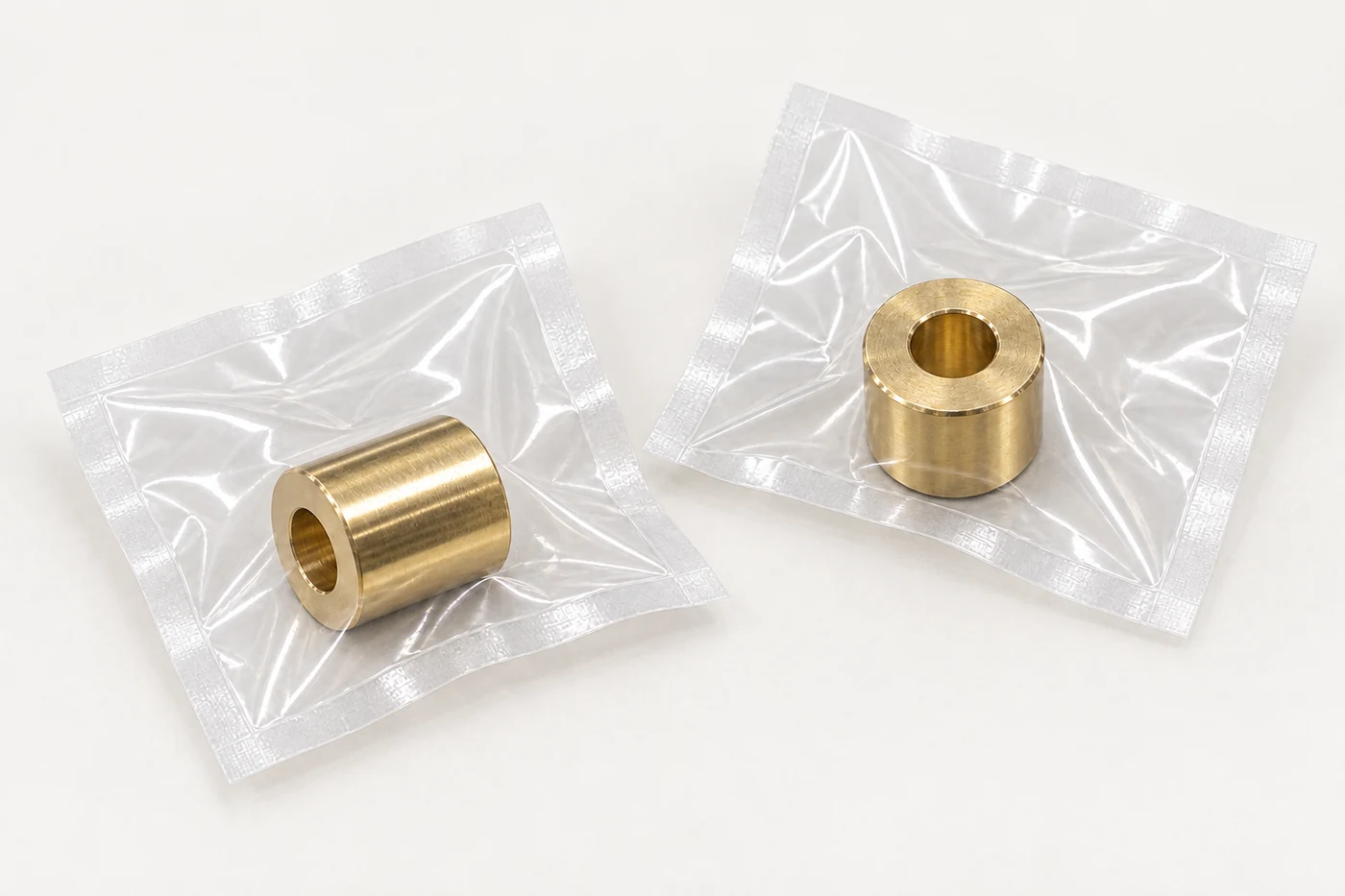
세척이 끝난 부품은 작업대, 손, 운반 용기와 포장재를 거치며 다시 오염될 수 있습니다. 필요한 청정 수준에 맞춰 접촉 재료와 작업 환경을 정하고, 세척부터 다음 사용 시점까지 보호가 이어지도록 해야 합니다.
- 접촉: 장갑·지그·용기가 오염이나 섬유를 다시 옮기는지 확인합니다.
- 대기: 건조 후 노출 시간과 주변 작업에서 들어오는 오염을 관리합니다.
- 포장: 요구 수준에 맞는 포장재를 선택하고, 포장 내부에서 부품이 비벼지는 조건도 살펴봅니다.
04검사 설계와 추출
표준과 검사 범위
청정도 검사에서 표준 번호는 측정 방법을 맞추는 출발점입니다. 번호만 적어서는 어느 부위를 검사하고 어떤 오염을 얼마나 허용할지까지 정해지지 않습니다.
입자와 표면막
ISO 16232:2018은 자동차의 기능상 중요한 부품과 시스템에 대한 입자 오염 검사·기록을 다룹니다. 유막·그리스막, 비정량 육안 평가는 적용 범위에서 제외되므로 입자 검사 성적만으로 탈지 상태까지 합격이라고 판단할 수 없습니다. 다른 산업에서 참고할 때도 해당 부품에 적용할 방법과 변경 조건을 명확히 해야 합니다.
| 문서·요구사항 | 확인할 역할 | 별도로 정할 내용 |
|---|---|---|
| ISO 16232 | 입자 오염의 검사·기록 체계 | 검사 영역과 부품별 허용 한계 |
| VDA 19.1 | 자동차 부품의 기술적 청정도 검사 | 적용 판본과 구체적인 시험 조건 |
| 고객 도면·검사 협약 | 제품의 실제 합격 요구사항 | 입자·막 오염의 지표, 단위와 판정 절차 |
판본과 기능 요구
2026년 9월 확인 기준 ISO 16232:2018이 현행 발행판이며 후속 DIS 개정안이 진행 중입니다. VDA 19.1은 2026년 2월 제3차 개정판의 발행이 확인되므로 2015년판을 최신판으로 적지 않아야 합니다. 공개된 2025년 초안의 세부 규칙도 최종판 조항과 동일하다고 가정하지 않습니다.
ISO 16232 자체는 모든 부품에 공통인 허용 입자 크기나 질량을 지정하지 않습니다. 기능 간극, 접착·도금 요구와 고장 영향을 검토한 뒤 검사 위치, 크기 범위, 허용 개수·최대 크기, 필요 시 막 오염 기준을 합의해야 합니다. 이 조건이 있어야 서로 다른 업체의 성적서를 같은 기준으로 검토할 수 있습니다.
추출·블랭크·여과
내부 유로와 홈의 입자는 표면 사진만으로 평가하기 어렵습니다. 추출액에 입자를 회수해 필터로 검사하더라도, 충분히 떼어냈는지와 회수 중 결과가 달라지지 않았는지를 확인해야 합니다.
검증 절차의 역할
추출 검증에서는 같은 부품에 정한 조건으로 반복 추출하고 회차별 검출량의 감소를 봅니다. 이 감소곡선은 시험 추출 조건의 적합성을 확인하는 절차이며, 생산 세척이 초기 오염의 일정 비율을 제거했다는 뜻은 아닙니다. 추출이 너무 강해 모재나 코팅에서 새 입자가 발생하는지도 살펴야 합니다.
| 검증 | 확인하는 문제 | 그 시험만으로 알 수 없는 것 |
|---|---|---|
| 반복 추출·감소곡선 | 부품에서 충분히 회수되는가 | 생산 세척의 절대 제거율 |
| 블랭크 공시험 | 용액·장치·취급에서 오염이 더해지는가 | 부품 내부에서 미추출된 양 |
| 회수 시험 | 알려진 입자가 전달·여과·분석 중 손실되는가 | 실제 부품의 모든 입자가 떨어지는가 |
공시험과 오염 경로
블랭크는 부품 없이 실제 시험과 같은 장치·용액·취급 과정을 거치는 공시험입니다. 높은 블랭크를 부품 측정값에서 단순 차감해 합격으로 바꾸어서는 안 됩니다. 그렇다고 높은 블랭크를 곧바로 부품 불합격과 동일시하지도 말고, 정량 신뢰성과 한계 적합성을 구분해 합의한 절차로 재시험 여부를 판단합니다.
여과 단계에서는 분석 대상에 맞는 필터와 입자 부하, 용기·배관의 헹굼, 필터 취급과 건조 조건을 맞춥니다. 입자 겹침은 영상 계수를 흔들고 잔류 용액이나 세정 성분은 중량값에 영향을 줄 수 있으므로, 검사 부품 수를 늘릴 때도 분석 가능성을 다시 확인해야 합니다.
05결과 해석과 유막
입자 결과 판독
입자 총질량이 작아도 기능 간극에 걸릴 긴 칩이 있을 수 있습니다. 반대로 최대 입자 하나만으로 전체 오염량이나 공정의 안정성을 설명하기도 어렵습니다.
측정 정의와 원본 영상
성적서에는 검사한 크기 범위와 입자 길이·폭의 정의가 필요합니다. 영상에서 측정한 최대 길이는 구형 입자의 직경과 다르며, 필터 위의 겹친 입자나 반사 때문에 분리된 영상은 계수와 최대값을 왜곡할 수 있습니다. 한계를 좌우하는 입자는 원본 영상을 함께 검토하는 편이 좋습니다.
| 지표 | 잘 보여주는 것 | 함께 확인할 것 |
|---|---|---|
| 크기별 입자 개수 | 오염의 분포와 변화 | 분석 크기 범위·겹침·분류 조건 |
| 최대 입자 길이 | 검출된 큰 입자의 존재 | 폭·형상·원본 영상과 변동성 |
| 필터 전후 질량 차이 | 회수 잔사의 총질량 | 건조·블랭크와 별도의 입자 크기 정보 |
환산 기준과 재질 확인
부품당·면적당 결과를 비교하려면 시험 수량, 검사 영역과 환산 기준이 같아야 합니다. 단순 계산 예로 5개 부품의 합동 추출에서 50개 입자가 나왔다면 부품당 평균은 10개지만, 각 부품에 10개씩 있었다는 뜻은 아닙니다. 이는 허용치가 아닌 산술 예시이며, 최대 입자 길이를 시험 수량으로 나누어서도 안 됩니다.
섬유 형태와 반사성은 유용한 광학 분류이지만 특정 재질이나 무해함을 입증하지는 않습니다. 금속 성분이 중요한 원인 조사에는 SEM/EDS 등의 별도 분석을 검토하고, ‘불검출’도 검사한 크기·영역과 방법의 검출 능력 안에서 해석해야 합니다.
유막과 비휘발성 잔류물
입자 검사를 통과한 표면에도 접착이나 도금에 영향을 줄 잔류막이 남을 수 있습니다. 막 오염 검사는 ‘얼마나 남았는가’, ‘무엇이 남았는가’, ‘표면이 잘 젖는가’ 중 필요한 질문에 맞춰 선택해야 합니다.
NVR의 측정 조건
비휘발성 잔류물인 NVR은 정한 추출액을 증발시킨 뒤 남는 잔사의 질량으로 평가합니다. 불용성 입자를 먼저 여과했는지에 따라 결과의 의미가 달라지므로, 추출액·검사 면적·여과·증발 조건과 블랭크를 함께 기록해야 합니다. 입자 필터의 질량과 같은 mg 단위를 써도 서로 대체할 수 없으며, 물과 유기용매가 회수하는 잔류물도 다릅니다.
| 방법 | 주요 질문 | 판정 시 한계 |
|---|---|---|
| NVR | 추출·증발 후 잔사가 얼마나 남는가 | 질량만으로 성분이나 분포를 알 수 없음 |
| FTIR | 오염의 적외선 스펙트럼은 무엇과 대응하는가 | 분석 위치와 성분 확인 근거가 필요 |
| 형광 | 검출 가능한 오염의 신호가 어떻게 변하는가 | 실제 오염·소재별 검증과 기준 시편 필요 |
| 접촉각 | 정한 액체가 표면에서 어떻게 젖는가 | 잔사 질량·성분의 직접 측정이 아님 |
| 이온 크로마토그래피 | 추출액에 목표 이온이 얼마나 있는가 | 이온별 추출·분리·정량 조건 필요 |
현장 지표와 기능 검증
형광 측정은 실제 미세척품과 양품·불량품으로 검출 가능성과 판정 구분을 확인해야 합니다. 신호는 오염 종류뿐 아니라 소재의 광학 특성과 측정 거리 등에 영향을 받으므로 다른 표면의 수치를 그대로 합격선으로 가져오지 않습니다. FTIR은 오염 성분의 확인에 활용하고, 특정 이온이 문제라면 이온별 분석 조건을 따로 정합니다.
접촉각은 소재·표면 화학과 액적을 놓는 방법을 맞춰 비교하며, 표면 거칠기의 영향도 해당 조건에서 확인합니다. 서로 다른 측정법의 수치를 직접 비교하거나 작은 각도만으로 잔류물이 없다고 단정해서는 안 됩니다. 최종적으로는 선택한 지표가 실제 접착·도금 등 후공정 결과를 구분하는지 검증해야 합니다.
06양산 승인과 발주
양산 검증과 불량 추적
한 번의 시제품 세척 성공은 양산 전체의 청정도를 보증하지 않습니다. 실제 양산에서는 가공유의 종류와 묻은 양, 세척 전 대기시간, 바스켓 적재량, 세정욕의 누적 오염이 함께 바뀝니다. 승인 시험은 가장 깨끗한 소량 시편보다 실제 생산에서 예상되는 불리한 조건을 포함해야 합니다.
조건 범위와 채취 시점
먼저 동일한 추출·분석법으로 비교할 수 있도록 검사 절차를 확정합니다. 이어 깊은 홀이나 넓은 접촉면이 있는 형상, 최대 허용 적재, 세척 전 최대 대기시간, 관리 한계에 가까운 세정욕 상태를 조합해 결과를 비교합니다. 합격한 설정값 하나만 기록하지 말고 그 결과를 얻은 적재 방식·헹굼·건조 조건까지 묶어 승인합니다.
공정 중간 시편과 최종 포장품은 목적이 다릅니다. 세척 직후 채취는 세척 성능을, 건조 후 채취는 건조·취급 영향을, 운송을 거친 포장품 검사는 인도 상태를 판단하는 데 도움이 됩니다. 동일한 부품을 반복 추출하면 먼저 수행한 검사가 오염을 제거하므로, 공정 단계 비교에는 가능한 한 동등한 별도 시편을 사용합니다.
| 관찰 결과 | 우선 비교할 항목 | 다음 조치 |
|---|---|---|
| 큰 금속 입자만 간헐적으로 증가 | 버·칩 걸림, 홀 교차부, 바스켓 마찰 | 문제 입자 형상과 발생 공정 대조, 디버링·이송 조건 확인 |
| 입자는 합격하지만 접착·도금 문제 발생 | 유막·세척제 잔사, 헹굼, 표면 상태 | 표면막 분석과 실제 후공정 시험을 연결 |
| 세척 직후 합격, 포장 후 불합격 | 건조 공기, 장갑·트레이·봉투, 보관·운송 | 단계별 별도 시편과 포장재 공시험으로 유입 지점 분리 |
| 검사일·검사실에 따라 값이 크게 변동 | 블랭크, 추출 범위, 필터 겹침, 판독 설정 | 공정 변경 전에 검사법과 시편 취급의 일치성 확인 |
변경 관리와 재세척
세척제나 절삭유를 바꾸면 기존 형광 기준과 용해·헹굼 거동이 달라질 수 있습니다. 소재·표면처리·필터·바스켓·포장재 변경도 영향 범위를 검토하고 필요한 항목을 재검증합니다. 정기 검사 주기는 공정 변동과 기능 위험을 근거로 정하며, 모든 제품에 같은 주기를 적용하지 않습니다.
불합격품을 반복 세척해 합격시킨 경우에는 최초 불합격, 재세척 횟수와 조건, 재검사 결과를 함께 남깁니다. 추가 세척으로 변색·부식·치수 변화 또는 표면 손상이 발생하지 않았는지도 확인합니다. 재검사 합격만으로 앞선 양산 로트의 영향 범위가 해소되는 것은 아닙니다.
도면·발주 사양과 비용
발주서의 ‘세척 후 납품’만으로는 양쪽이 같은 품질을 기대하기 어렵습니다. 외관상 기름기를 없애는 작업과 기능면의 입자·유막을 정량 관리하는 작업은 검사와 포장까지 달라집니다. 어느 면을, 어떤 오염에 대해, 어떤 방법으로, 어느 시점에 판정할지를 먼저 합의해야 합니다.
청정도 요구서의 필수 항목
| 사양 항목 | 합의할 내용 |
|---|---|
| 기능과 대상면 | 유로·밀봉면·접착면 등 중요 영역, 검사 제외면과 경계, 분해 여부 |
| 판정 항목 | 입자 크기 구간별 개수·최대 크기·질량 중 필요한 항목, 유막·이온 잔류물의 별도 요구, 각 항목의 허용한계와 합격·불합격 판정 규칙 |
| 기준 단위 | 부품당·면적당 등 분모, 내부면 포함 면적 산정, 여러 부품 합동 시험의 수량 |
| 검사 절차 | 표준 판본, 검증된 추출법, 블랭크, 여과·분석 조건, 검출 범위와 보고 형식 |
| 채취와 판정 시점 | 로트 정의·채취 방식·시료 수, 최종 포장 후 또는 입고 후 등 인도 상태 |
| 보존과 포장 | 방청제 허용 여부, 건조 상태, 접촉 포장재, 개별·구획 포장, 개봉·보관 조건 |
| 이탈과 변경 | 재세척·재검사 절차, 부적합 로트 처리, 공정·재료 변경 시 재승인 범위 |
‘입자 없음’ 대신 검사 가능한 크기 범위와 검출·판독 조건을 정하고, 해당 범위에서의 판정 규칙을 씁니다. 도면의 특정 홀만 중요하다면 전체 외면의 평균값으로 대신하지 않도록 영역을 표시합니다. 방청유가 필요한 강재를 완전 탈지 상태로 납품하도록 요구한다면, 부식 방지와 후공정 청정도를 함께 만족할 대안을 정해야 합니다.
총비용과 검토 자료
비용은 세척 시간만으로 비교하지 않습니다. 전처리와 적재 인력, 세정욕·필터 관리, 물과 에너지, 건조, 검사 시편, 포장, 재작업과 고객 조립 불량까지 포함해야 합니다. 기능상 필요하지 않은 수준까지 전면을 관리하면 검사와 포장 비용이 늘지만, 중요한 유로나 접착면을 빠뜨리면 후공정 손실이 더 커질 수 있습니다.
검토 자료에는 도면과 소재·표면처리, 오염원으로 쓰는 가공유·연마제 정보, 후공정, 현재 포장 방식, 불량 사진과 검사 성적서를 포함합니다. 기존 정밀 CNC 가공 조건 및 패시베이션·표면처리 요구와 연결해 검토하면 서로 충돌하는 사양을 줄일 수 있습니다. 청정도 수치나 시험법이 아직 정해지지 않았다면 기능 위험과 시편 시험 범위부터 정리해 제품문의·개발의뢰 자료로 전달하시면 됩니다.
English Technical Overview
Precision metal-parts cleaning and cleanliness control help reduce assembly and functional failures that dimensional inspection alone may miss. A small chip can block a passage, while barely visible machining oil can interfere with bonding and surface treatment. A shiny appearance is therefore insufficient to establish delivery acceptance.
The objective is to meet function-based residue criteria using an agreed inspection method at the specified delivery condition. Alongside contaminant removal, control rinsing, drying, handling and packaging, and assess particles and surface films using appropriate separate methods.
Define the contamination
Distinguish particles, films and ionic residues, starting with risks on functional surfaces.
Match the geometry
Check liquid access, exchange and drainage, and design loading and drying together.
Align inspection and delivery
Agree on extraction validation, blanks, analysis conditions and acceptance after packaging.
01Function and contamination sources
Function and Cleanliness
A precision part can meet its dimensional tolerances and still malfunction because of residual contamination. Cleanliness should be judged by how remaining substances affect assembly and use, rather than by surface shine.
Particles, Films, and Ions
Chips and abrasive particles can obstruct narrow passages or become trapped between moving contact surfaces and cause damage. The risk from particles of the same size varies with component clearance, particle material and shape, and the paths along which they can move.
| Contamination type | Typical residues | Functional considerations |
|---|---|---|
| Particles | Metal chips, abrasives, fibers | Blocked passages, damaged contact surfaces, migration during assembly |
| Film residues | Machining oil, grease, corrosion preventives | Surface condition before bonding, painting, or coating |
| Ionic residues | Salts and some constituents of process chemicals | Corrosion in the presence of moisture and leakage-current risks in electrical components |
These three types are not completely separate categories. Particles may adhere to an oil film, and dried marks may contain ionic constituents, so removing one type does not establish overall cleanliness.
Functional Surfaces and Delivery Condition
The cleaning objective must be tied to the next operation. A protective film retained to prevent storage corrosion may need removal before bonding or coating, so intended surface treatments must be distinguished from unwanted contamination.
Review sealing faces, assembly contact surfaces, and internal passages as well as visible exterior surfaces. Identifying where contamination can migrate or make contact helps align the cleaning scope with functional risk.
Contamination Sources and Traps
The burden on final cleaning depends strongly on contamination introduced by earlier manufacturing operations. Separating cutting chips, grinding and polishing residues, and machining fluids by process helps distinguish a chemistry problem from excessive incoming contamination.
Upstream Sources
An attached burr and a metal particle that has already detached require different treatment. Even after cleaning removes loose particles, a burr at a bore intersection can detach later and become a new contamination source, so the deburring process also needs review.
Evaluating polished and machined parts under an identical assumption can conceal important differences in their contamination. Cleaning trials should use parts carrying the actual process fluids and residues, without unplanned wiping that changes their incoming condition.
Cross-Drilled and Blind Holes
Merely getting cleaning fluid into a blind hole or internal intersection is insufficient. Trapped air must escape, contaminated fluid must be replaced, and liquid must drain, so review exits and draining orientation as well as entrance size and direction.
- Entrance: Check whether nozzle orientation or the fixture obstructs fluid access.
- Interior: Examine steps, intersections, and blind ends for retained chips or trapped air.
- Exit: Confirm a route for detached particles and contaminated liquid to leave the part.
The arrow in the section diagram indicates a connected access path for cleaning liquid, while the amber accents mark locations to check for retention. A connected passage does not guarantee equally effective liquid exchange at its blind end.
02Cleaning processes and loading
Cleaning Media and Material Compatibility
Select the cleaning medium for both the contamination to remove and the material to protect. Treating either aqueous or organic-solvent cleaning as the default for every precision part does not adequately address surface damage or residue.
Matching Contamination and Medium
Aqueous cleaners include neutral, alkaline, and acidic formulations, with different degreasing behavior and material compatibility. Organic solvents also vary, so effective removal of machining oil does not establish removal of water-soluble residues.
| Medium family | Selection checks | Downstream conditions |
|---|---|---|
| Aqueous | Contamination type, cleaner formulation, chemical resistance of the alloy and surface treatment | Rinsing to reduce chemical residue, followed by effective drainage and drying |
| Organic solvent | Contaminant solubility and compatibility with materials, polymers, and seals | Equipment, recovery, and drying conditions suited to the selected solvent |
Increasing temperature, concentration, or time does not always improve the result. Check discoloration, surface attack, and chemical residue alongside soil removal, and establish the operating window through trials with the actual material and contamination.
Alloys and Surface Treatments
Chemical compatibility deserves particular attention for aluminum, magnesium, and zinc alloys. For example, the alkaline cleaner Elma Clean 300 calls for preliminary resistance testing on these alloys, so a general metal-cleaning designation is insufficient for approval.
When plating, oxide coatings, or assembled polymers and seals are present, compatibility cannot be assessed from the base metal alone. Trials should verify preservation of the required surface condition as well as immediate appearance, translating supplier guidance into validated conditions for the specific part.
Mechanical Action and Loading
Even suitable chemistry has limited effect when it cannot reach the required surface. Select the process for both its action in detaching contamination and its flow in carrying the released material away.
Cleaning Action for the Geometry
Spraying, immersion, ultrasound, and pressure-reduction processes assist cleaning in different ways. Complex parts may benefit from a combination, but including a particular technology does not demonstrate that all internal surfaces have been cleaned.
| Method | Main action | Geometry and loading checks |
|---|---|---|
| Spraying | Directed liquid jets clean the surface | Nozzle alignment and spray shadows behind fixtures and parts |
| Immersion and flow | Submersion and fluid movement help transport contamination away | Routes for trapped air to escape and contaminated liquid to be replaced |
| Ultrasound | Cavitation in the liquid assists contaminant detachment | Wetting, sensitive surfaces, and overlapping parts |
| Pressure reduction and cycling | Assist cleaning of complex internal geometry | A suitable chamber and conditions for fluid access and discharge |
Baskets and Part Orientation
Overlapping parts can restrict fluid access at contact surfaces and allow contamination to redeposit on parts below. Define part spacing, support points, and hole orientation as well as basket load to preserve room for cleaning and drainage.
Results from a few widely spaced trial parts should not be transferred directly to a densely loaded production batch. Use the actual load and fixture, and assess part damage and drainage together when rotation or oscillation is needed.
An open carrier holding shafts apart illustrates the need to design both spacing and support points. Short bushings and thin sheet parts need different supports, so check contact marks and drainage for the actual geometry.
03Process control and recontamination
Bath and Rinse Management
Contamination removed from parts enters the cleaning bath, so the condition of the fluid changes during use. Maintaining a good result obtained with fresh fluid requires control of incoming soil, removal capacity, and chemical concentration.
Soil Load and Concentration
A particulate filter alone cannot manage every oil residue or dissolved contaminant. Check filter flow, differential pressure, and capture performance, and address oil separately with a method suited to the cleaner’s emulsifying or oil-splitting behavior.
Concentration is not merely a value to set when preparing the bath. Account for chemical carryout and replenishment history, and track it using a method specified for the formulation so concentration drift is not confused with soil accumulation.
Rinse Water and Residues
Rinsing reduces cleaner and released contamination remaining on the part. Heavy dragout from the preceding stage quickly contaminates the rinse, so drainage and water replacement matter alongside the number of tanks.
Rinse-water conductivity primarily tracks changes in ionic constituents in the water. A low reading does not account for every nonionic organic residue or particle attached to a part, and acceptable tank-water quality is not itself a surface acceptance result.
- Cleaning bath: Record concentration and soil-load trends together.
- Circulation system: Check filter condition, flow, and nozzle blockage.
- Rinsing: Manage incoming and used water together with liquid carried over on parts.
Drying and Recontamination
Drying is not complete merely because contaminated water has evaporated. Poor drainage or rinsing can leave constituents on the surface, so marks after drying call for review of both the dryer and the preceding stages.
Drainage and Drying Paths
Liquid retained in blind holes and recesses depends on part orientation. An exterior can be dry while liquid remains inside, so use orientation to aid drainage and assess hot-air or vacuum drying for the actual geometry.
Prolonged wetness after cleaning can cause corrosion depending on the material and remaining substances. Review drying delays, trapped liquid, and required corrosion protection together, without adding a preservative that may interfere with subsequent bonding or coating.
Handling and Protective Packaging
When using compressed-air blow-off, check whether the air itself introduces contamination. Water, oil, and particles can enter through the compressor and distribution system, so an oil-free compressor designation alone does not establish the cleanliness of air contacting the part.
Cleaned parts can be contaminated again by benches, hands, transport containers, and packaging. Select contact materials and the working environment for the required cleanliness level, maintaining protection from cleaning through the next use.
- Contact: Check whether gloves, fixtures, or containers transfer contamination or fibers.
- Waiting: Control exposure after drying and contamination from surrounding operations.
- Packaging: Select materials for the required level and examine conditions that allow parts to rub inside the package.
04Inspection design and extraction
Standards and inspection scope
A cleanliness standard provides a starting point for consistent measurement. Its number alone does not define the inspection area, the contamination of concern or the acceptable amount.
Particles and films
ISO 16232:2018 addresses the inspection and documentation of particulate contamination on functionally relevant automotive components and systems. Its scope excludes oil and grease films and nonquantitative visual assessments. A particle inspection result therefore does not establish acceptable degreasing; use in another industry also requires a clear agreement on applicable methods and adaptations.
| Document or requirement | Role to confirm | Items requiring a separate definition |
|---|---|---|
| ISO 16232 | Particle inspection and documentation framework | Inspection area and component-specific limits |
| VDA 19.1 | Technical cleanliness inspection of automotive components | Applicable edition and detailed test conditions |
| Customer drawing and inspection agreement | Actual product acceptance requirements | Particle and film metrics, units and decision procedure |
Editions and functional requirements
As verified in September 2026, ISO 16232:2018 remains the current published edition, with a subsequent DIS revision in development. VDA 19.1 has a third revised edition dated February 2026, so the 2015 edition should no longer be described as the latest. Detailed rules in the public 2025 draft should not be assumed identical to the final edition.
ISO 16232 does not prescribe a universal allowable particle size or mass for all components. Review functional clearances, bonding or plating requirements and failure consequences before agreeing on inspection locations, size ranges, allowable counts and maximum size, plus film criteria where needed. These definitions make supplier reports comparable.
Extraction, blanks and filtration
Photographs alone cannot readily assess particles inside passages and grooves. Even when particles are extracted into a liquid and inspected on a filter, the test must confirm adequate removal and control changes during recovery.
Roles of validation checks
Extraction validation repeats the extraction on the same component under defined conditions and examines the decline in recovered contamination. This decay curve assesses the test conditions; it does not prove that production cleaning removed a particular fraction of the original contamination. The procedure must also check whether aggressive extraction generates new particles from the substrate or coating.
| Check | Question addressed | What it cannot establish alone |
|---|---|---|
| Repeated extraction and decay curve | Is recovery from the component adequate? | Absolute removal efficiency of production cleaning |
| Blank test | Do liquids, equipment or handling add contamination? | Contamination left unextracted inside the component |
| Recovery test | Are known particles lost during transfer, filtration or analysis? | Whether every particle detaches from the actual component |
Blanks and contamination paths
A blank follows the actual equipment, liquid and handling procedure without the component. A high blank must not simply be subtracted from the component result to obtain a pass. Nor does it automatically establish component failure: distinguish quantitative reliability from compliance with the limit, and use the agreed procedure to decide whether retesting is needed.
Filtration requires a suitable filter and particle loading, controlled rinsing of vessels and lines, and consistent filter handling and drying. Overlapping particles can distort image counts, while residual liquid or cleaning chemicals can affect mass results. Increasing the number of components in a test therefore requires another check of analytical suitability.
05Result interpretation and films
Reading particle results
A low total particle mass can still include a long chip capable of interfering with a functional clearance. Conversely, the largest particle alone cannot adequately describe total contamination or process stability.
Definitions and original images
The report needs an inspected size range and definitions of particle length and width. Maximum image-based length differs from the diameter of a spherical particle; overlapping particles or reflections that split one particle into several images can distort counts and maxima. Review the original images of particles that determine compliance with a limit.
| Metric | What it shows well | Additional checks |
|---|---|---|
| Counts by size class | Contamination distribution and changes | Analysis size range, overlap and classification settings |
| Maximum particle length | Presence of a large detected particle | Width, shape, original image and variability |
| Filter mass difference | Total mass of recovered residue | Drying, blank and separate particle size information |
Reporting basis and material verification
Comparing results per component or per unit area requires matching the sample quantity, inspection area and normalization basis. As a simple arithmetic example, 50 particles from a pooled extraction of five components gives an average of ten per component; it does not mean that each component carried ten. This example is not an acceptance limit, and maximum particle length must not be divided by the sample quantity.
Fiber shape and reflectivity are useful optical classifications, but they do not establish a specific material or prove harmlessness. Consider separate analysis such as SEM/EDS when metallic composition matters to the investigation. Interpret “not detected” within the inspected size range, area and detection capability of the method.
Films and nonvolatile residue
A surface that passes particle inspection can still retain a film that affects bonding or plating. Select a film assessment according to the question: how much remains, what it is, or how well the surface wets.
NVR measurement conditions
Nonvolatile residue, or NVR, is evaluated as the mass remaining after evaporation of a specified extract. Record the extraction liquid, inspected area, filtration, evaporation conditions and blank, because prior removal of insoluble particles changes the meaning of the result. NVR and particle-filter mass are not interchangeable despite sharing mg units, and water and organic solvents recover different residues.
| Method | Main question | Interpretation limit |
|---|---|---|
| NVR | How much residue remains after extraction and evaporation? | Mass alone does not identify composition or distribution |
| FTIR | What does the contaminant’s infrared spectrum correspond to? | Requires a defined analysis location and evidence for identification |
| Fluorescence | How does the signal from detectable contamination change? | Requires validation for the actual contaminant and substrate, with reference samples |
| Contact angle | How does a specified liquid wet the surface? | Does not directly measure residue mass or composition |
| Ion chromatography | How much of a target ion is present in the extract? | Requires ion-specific extraction, separation and quantification conditions |
Production indicators and functional validation
Validate fluorescence detection and discrimination using actual uncleaned, acceptable and defective parts. The signal depends on substrate optics and measurement distance as well as the contaminant, so a value from another surface should not be adopted directly as an acceptance threshold. Use FTIR to help identify contamination, and define ion-specific analysis conditions when particular ions are a concern.
Compare contact angles with consistent substrate, surface chemistry and drop-deposition methods, and assess roughness effects under the relevant conditions. Do not compare values from different methods directly or treat a small angle as proof of zero residue. Finally, verify that the chosen indicator distinguishes actual downstream outcomes, such as bonding or plating performance.
06Production approval and purchasing
Production validation and failure tracing
A successful cleaning trial on one prototype does not guarantee cleanliness throughout production. The type and amount of machining fluid, waiting time before cleaning, basket load and accumulated bath contamination all change during production. Approval trials should include the adverse conditions expected in actual production, rather than relying on a small load of relatively clean samples.
Operating ranges and sampling points
First establish the inspection procedure so that results can be compared using the same extraction and analysis method. Then compare combinations of challenging geometries, such as deep holes or broad contact surfaces, maximum permitted loading, maximum waiting time before cleaning and bath conditions close to their control limits. Approve the loading arrangement, rinsing and drying conditions together with the settings that produced the result.
In-process samples and finally packaged parts serve different purposes. Sampling immediately after cleaning helps evaluate cleaning performance; sampling after drying helps assess drying and handling; testing packaged parts after transport helps evaluate the delivery condition. Repeated extraction of the same part removes contamination during the earlier test, so comparisons between process stages should use equivalent separate specimens where possible.
| Observation | First comparisons | Next action |
|---|---|---|
| Intermittent increases in large metallic particles | Burrs, trapped chips, intersecting holes and basket friction | Compare particle morphology with possible source processes; check deburring and transfer conditions |
| Particles pass, but bonding or plating problems occur | Oil films, cleaner residues, rinsing and surface condition | Connect film analysis with actual downstream process tests |
| Pass after cleaning, fail after packaging | Drying air, gloves, trays, bags, storage and transport | Separate entry points using independent samples at each stage and packaging blank tests |
| Large variation between inspection days or laboratories | Blanks, extraction scope, overlapping particles on filters and analysis settings | Check agreement in inspection methods and specimen handling before changing production |
Change control and recleaning
Changing a cleaner or machining fluid can change an established fluorescence reference as well as dissolution and rinsing behaviour. Changes to material, surface treatment, filters, baskets or packaging also require an impact review and appropriate revalidation. Set routine inspection frequency according to process variation and functional risk, rather than applying one frequency to every product.
If a failed part passes after repeated cleaning, retain the original failure, the number and conditions of recleaning cycles and the retest result. Also check for discolouration, corrosion, dimensional change or surface damage caused by additional cleaning. A passing retest alone does not resolve the potential impact on earlier production lots.
Drawing requirements, purchasing and cost
The purchasing instruction “deliver after cleaning” does not reliably establish a shared quality expectation. Removing visible grease and quantitatively controlling particles and films on functional surfaces require different inspection and packaging provisions. First agree which surfaces and contaminants will be assessed, by which method and at what point.
Essential items in a cleanliness specification
| Specification item | What to agree |
|---|---|
| Function and surfaces | Critical flow passages, sealing or bonding surfaces; excluded areas and boundaries; whether disassembly is required |
| Acceptance metrics | Required particle counts by size class, maximum size and/or mass; separate requirements for films and ionic residues; limits for each metric and pass/fail decision rules |
| Reference unit | Per component or per area; area calculation including internal surfaces; number of parts in a pooled test |
| Inspection procedure | Standard edition, validated extraction, blanks, filtration and analysis conditions, detection range and reporting format |
| Sampling and acceptance point | Lot definition, sampling approach and sample count; delivery condition, such as after final packaging or upon receipt |
| Preservation and packaging | Whether corrosion inhibitors are permitted; dryness; contact packaging materials; individual or compartmented packaging; opening and storage conditions |
| Deviations and changes | Recleaning and retesting, nonconforming lot disposition and reapproval scope following process or material changes |
Instead of simply requiring “no particles”, specify the detectable size range and detection and analysis conditions, then define the acceptance rule within that range. If a particular bore is critical, mark the region so that an average over the entire exterior cannot substitute for it. If steel requiring protective oil must be delivered fully degreased, agree on an alternative that satisfies both corrosion protection and downstream cleanliness.
Total cost and review inputs
Compare more than cleaning time. Include pretreatment and loading labour, bath and filter maintenance, water and energy, drying, inspection samples, packaging, rework and failures during customer assembly. Controlling every surface beyond functional needs increases inspection and packaging costs, while overlooking a critical flow passage or bonding surface can create greater downstream losses.
Review inputs should include drawings, material and surface treatment, information on machining fluids and polishing compounds, downstream processes, existing packaging, defect photographs and inspection reports. Reviewing these together with precision CNC machining conditions and passivation and surface-treatment requirements helps reduce conflicting specifications. If numerical limits or test methods have not yet been established, start with functional risks and the scope of sample testing when preparing a product or development enquiry.
추가 정보
검색엔진용 요약
정밀 금속부품 세척과 청정도 관리는 입자·유막·이온성 잔류물이 조립과 사용에 미치는 영향을 줄이기 위해 소재·형상에 맞는 세척, 헹굼, 건조와 재오염 방지를 연결하는 과정입니다. ISO 16232와 VDA 19.1의 검사 범위, 추출 검증과 블랭크, 입자 결과·NVR의 해석을 구분하고 실제 기능면과 최종 포장·인도 상태에 맞는 발주 기준을 정해야 합니다.
핵심 포인트 정리
- 치수 합격과 청정도 합격은 서로 다른 판정이며, 중요 기능면부터 검사 범위를 정합니다.
- 입자·표면막·이온성 잔류물을 구분하고 각 요구에 맞는 검사법을 선택합니다.
- 세척액과 소재 적합성뿐 아니라 막힌 홀의 액 교환·적재·배액을 함께 확인합니다.
- 반복 추출, 블랭크, 회수 시험은 역할이 다르며 검사 신뢰성을 각각 검증합니다.
- 입자 크기·개수·질량의 정의와 환산 분모를 맞추고, NVR을 입자 질량으로 대체하지 않습니다.
- 건조·취급·보관·포장을 포함한 인도 시점의 기준과 변경·재검사 절차를 합의합니다.
FAQ
눈에 보이는 칩이 없으면 청정도 합격입니까?
육안으로 보이지 않는 입자와 유막·이온성 잔류물이 남을 수 있습니다. 검사 대상 크기와 영역, 기능 위험에 맞는 지표를 정해야 하며, 광택이나 치수 합격만으로 청정도를 대신 판정하지 않습니다.
초음파 세척 시간을 늘리면 막힌 홀도 해결됩니까?
시간만 늘리기 전에 세척액이 내부에 도달하고 갇힌 공기가 빠지며 오염액이 교체되는지 확인합니다. 적재·자세·액 조건이 맞지 않으면 효과가 제한되고 민감한 표면은 손상을 받을 수도 있습니다.
ISO 16232를 적용하면 허용 입자 크기도 정해집니까?
이 표준은 자동차 기능 부품의 입자 오염 검사·기록 체계를 다루며 모든 부품에 공통인 허용 한계를 지정하지 않습니다. 제품 기능과 검사 영역을 근거로 크기·개수·질량 등 필요한 지표와 한계를 별도로 합의해야 합니다.
블랭크 값을 빼서 입자 결과를 보정해도 됩니까?
입자 검사에서 높은 블랭크를 단순히 차감해 합격으로 만들면 안 됩니다. 장치·용액·취급의 오염 유입을 조사하고 검사 신뢰성과 부품 적합성을 구분해 합의한 절차로 재시험 여부를 판단합니다.
NVR과 필터의 잔류 질량은 같은 값입니까?
NVR은 정한 추출액의 증발 뒤 남은 비휘발성 잔사를 평가하며, 입자 검사는 필터에 회수된 잔사를 다룹니다. 추출액과 여과 여부, 건조·증발 및 블랭크 처리 조건에 따라 의미가 달라지므로 같은 mg 단위라도 서로 바꿔 쓸 수 없습니다.
청정도 검토를 의뢰하려면 어떤 자료가 필요합니까?
도면과 중요 기능면, 소재·표면처리, 가공유·연마제, 후공정, 포장 조건을 준비합니다. 기준이 있으면 판본·한계·추출법·성적서를 함께 전달하고, 기준이 없다면 기능 위험과 시편 시험 범위부터 검토합니다.
관련 주제 확장 설명
패시베이션과 세척의 역할
패시베이션은 스테인리스 표면 상태와 내식성을 다루는 처리입니다. 유분·입자 제거와 목적이 같지 않으므로 전처리, 처리 후 헹굼·건조 및 최종 청정도 요구를 연결해 검토합니다.
접착·도금 전의 표면막
입자 검사가 양호해도 얇은 가공유나 세척제 잔사가 후공정에 영향을 줄 수 있습니다. 막 분석과 젖음성 같은 공정 지표는 실제 접착·도금 결과와의 관계를 확인한 뒤 관리 기준으로 사용합니다.
방청과 포장 사양의 충돌
부식 방지를 위해 남긴 막이 후공정에서는 제거 대상이 될 수 있습니다. 무방청유 요구를 단독으로 지정하기보다 보관 시간과 환경, 접촉 포장재, 개봉 후 사용 조건까지 함께 합의합니다.
내부 링크
치수와 표면 요구를 함께 정할 때는 CNC 가공 정밀도와 공차 설계를, 스테인리스의 전후처리 조건을 검토할 때는 패시베이션과 표면처리를 연결해 보실 수 있습니다. 전기 부품은 전기접점 표면막과 접촉저항을 통해 기능면 오염의 의미를 함께 살펴볼 수 있습니다.
부품 형상과 상류 공정은 정밀 CNC 가공 및 CNC·프레스 공정 비교와 연결해 검토합니다. 도면·후공정·검사·포장 요구는 제품문의·개발의뢰를 통해 전달하실 수 있습니다.