
접점 용착과 발열
접점 용착은 ‘전류가 너무 커서 붙는 현상’만으로 설명되지 않습니다. 투입 순간의 재충돌, 좁은 통전점의 국부 발열, 분리 때 생기는 금속 브리지와 아크, 접점을 떼어 내는 기구의 힘이 함께 작용합니다. 단자 온도가 낮거나 초기 접촉저항이 작아도 개방 실패가 생길 수 있습니다.
대책의 출발점은 소재 교체가 아니라 언제 손상이 만들어졌고, 어느 경로에서 전력 손실이 발생했는지를 나누는 것입니다. 부하 파형과 접점 운동, 구간별 전압강하, 접합 품질을 연결해야 용착 방지와 온도상승 억제를 동시에 설계할 수 있습니다.
돌입전류와 바운스의 중첩
구간별 손실과 열 방출 경로
금속 브리지·아크·개방 여유
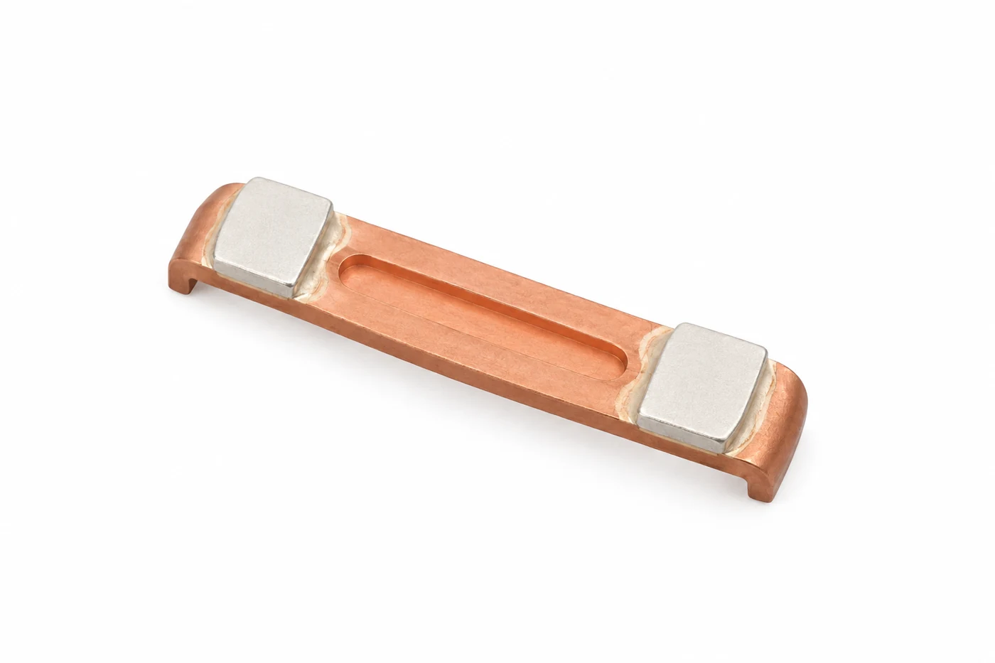
고장 증상과 증거의 분리
개방 명령 후에도 부하가 꺼지지 않는 현상은 원인 이름이 아니라 고장 증상입니다. 금속 접촉부의 용착, 전이물에 의한 기계적 걸림, 코일의 잔류 구동, 가동부 변형을 먼저 구별해야 합니다. 접촉기를 교체한 뒤 잠시 정상으로 돌아왔다고 해서 최초 원인이 접점 소재였다고 확정할 수는 없습니다.
발견 시점과 발생 시점
투입 때 생긴 작은 결합이 긴 통전 시간 동안 드러나지 않다가 다음 개방 명령에서 발견될 수 있습니다. 반대로 정상적으로 열렸던 접점도 이후 재투입에서 바운스와 돌입전류가 겹치면 새로운 손상을 입을 수 있습니다. 따라서 고장 직전의 차단 기록만 남기면 최초 원인을 잃기 쉽습니다.
기록의 기준점은 제어 명령, 코일 단자 전압·전류, 부하 전류, 접점 양단 전압입니다. 가능하다면 가동부 변위도 같은 시간축에 놓습니다. 비래칭 릴레이에서는 명령이 꺼졌는데 코일 전류가 유지되는 경우와, 코일 전류가 충분히 사라졌는데 접점이 분리되지 않는 경우의 후속 검토 대상이 다릅니다.
래칭 릴레이는 코일 전원을 끊어도 설정 상태를 유지하도록 설계됩니다. 이런 제품에서는 단순한 전원 제거를 개방 명령으로 해석하지 말고, 지정된 리셋 입력이 실제로 인가되었는지부터 확인합니다.
| 처음 확인할 증상 | 원인 분류에 필요한 증거 | 성급하게 바꾸지 않을 항목 |
|---|---|---|
| 투입 직후 반복 재개방 | 접점 전압 펄스와 부하 전류, 코일 전압 강하의 동시성 | 소재만 변경하기 전에 바운스와 전원 채터링을 구별합니다. |
| 닫힌 상태에서 전압강하 증가 | 접점부·캐리어·접합부·단자부의 비중복 구간 측정 | 전체 단자 저항을 곧바로 접점 계면 저항으로 해석하지 않습니다. |
| 개방 명령 후 전류 지속 | 코일 감쇠, 가동부 움직임, 분리 전 원상태와 접점쌍의 위치 관계 | 전원 차단과 원상태 기록 전에 두 접점을 억지로 떼지 않습니다. |
| 고장전류 중 순간 접점 들림 | 순간 피크, 들림 시점, 아크 지속, 보호장치 차단 이력 | 일반 통전 정격만으로 고장전류 적합성을 판정하지 않습니다. |
분해 전의 원상태 보존
현장에서는 우선 설비를 안전하게 격리하고 저장 에너지를 포함한 무전압 상태를 확인합니다. 분리·세척·연마·재체결은 접촉면의 전이물, 체결 흔적과 피막을 바꾸므로 초기 기록보다 먼저 수행하지 않습니다. 부품 방향과 짝을 표시하고, 양쪽 접촉면 및 단자·접합부의 위치 관계를 함께 보존합니다.
확대 관찰에서 돌기와 홈이 서로 대응하면 재료 전이와 기계적 걸림을 검토할 수 있습니다. 그러나 표면 색이나 거친 흔적만으로 용착 온도, 합금 조성 또는 발생 시점을 확정할 수는 없습니다. 필요에 따라 단면, 성분 분석과 공정 이력을 추가하고, 파형과 위치별 손실 측정이 가리키는 원인과 대조합니다.
고장품 한 개의 외관보다 같은 로트의 미사용품, 직전 정상 시료와 조건 변경 전후의 차이가 판단에 유용합니다. 부품 로트, 실제 배선, 코일 보호회로, 부하의 초기 상태가 같았는지 먼저 맞춥니다. 안전 기능에 영향을 주는 불개방은 접점을 떼어 임시 복구하는 방식으로 처리하지 않고 장치의 보호·고장 감지 설계까지 검토합니다.
투입·차단 순간의 접점 용착
접점 용착은 접점 두 개가 통째로 녹아 붙는 현상만을 뜻하지 않습니다. 맞닿은 면의 일부에 생긴 작은 금속 결합도 정상적인 개방 운동으로 끊어 내지 못하면 불개방을 일으킵니다. 반대로 약한 결합이 개방 과정에서 끊어지더라도, 평소보다 늦게 열리거나 표면에 전이물이 남는 변화가 먼저 나타날 수 있습니다.
미세 통전점과 금속 브리지
처음 맞닿는 순간에는 접점의 보이는 면적 전체가 동시에 전류를 받지 않습니다. 표면 돌기의 일부가 먼저 연결되고, 이 좁은 통로로 전류가 집중됩니다. 전류가 커지는 속도에 비해 접촉력이 형성되는 속도가 늦으면 초기 통전점의 열 부담이 커질 수 있습니다.
여기서 구별할 것은 닫힌 상태의 저항 발열과 분리 중의 아크 발열입니다. 닫힌 접점에서는 작은 통전점의 저항 손실로 국부 연화나 용융이 생길 수 있습니다. 바운스나 개방으로 접촉부가 벌어질 때에는 가늘어진 용융 금속이 양쪽을 잇는 브리지로 남았다가 끊어지는 단계가 나타날 수 있습니다.
금속 브리지는 고체가 맞닿은 상태도, 완전히 차단된 빈 공간도 아닙니다. 브리지가 파단한 직후에는 방출된 금속증기 속에서 방전이 이어질 수 있으므로, 접점이 움직이기 시작했다고 전류가 즉시 사라지는 것은 아닙니다. 순금속 접점의 고속 관찰 연구에서는 분리 중 브리지가 끊어진 뒤 다시 연결되는 현상도 확인되었습니다.
이 연구가 특정 은합금 접점의 용착 한계나 수명을 직접 알려 주는 것은 아닙니다. 실무에서 가져올 결론은 분리 과정을 단순한 ‘닫힘→열림’ 신호로만 해석하지 말아야 한다는 점입니다. 금속 연결, 아크 통전, 최종 전류 차단은 서로 다른 시점일 수 있습니다.
재접촉과 다음 개방의 실패
투입 바운스 중에는 접촉·분리가 짧게 반복됩니다. 분리 때 가열된 표면이 다시 눌리면서 결합하면, 바로 이어지는 정상 통전 구간에는 외관상 문제가 없어 보일 수 있습니다. 이미 만들어진 용착은 다음 개방 명령에서야 발견되기도 합니다.
재접촉의 결과는 아크가 지속된 시간 하나로 정해지지 않습니다. 그 구간을 실제로 통과한 전류, 가열된 위치와 면적, 표면에 남은 용융물, 재충돌과 이후 분리 운동이 함께 작용합니다. 아크 에너지는 해당 구간의 접점 전압과 전류를 시간에 따라 함께 평가해야 하며, 정격전압에 피크 전류와 전체 바운스 시간을 곱한 값으로 대신할 수 없습니다.
반복 개폐는 다음 동작의 출발 조건도 바꿉니다. 한쪽의 돌기와 반대쪽의 함몰은 맞닿는 위치를 이동시키고, 마모는 접촉 여유를 소모할 수 있습니다. 낮은 초기 저항이 유지되더라도 이런 기하학적·동적 변화까지 없다고 판단할 수는 없습니다.
파형과 실제 분리의 대응
고장 재현에서는 부하 전류, 접점 양단 전압, 코일 구동 및 접근 가능한 실제 접점 변위를 같은 시간축에 놓습니다. 접점 전압이 올라가면서 전류가 계속 흐르는 구간은 아크 통전을 의심할 근거가 됩니다. 다만 전압 파형만으로 금속 브리지와 재접촉을 확정하지 말고, 변위나 관찰 결과를 대조해야 합니다.
아크가 좁은 틈을 연결하면 접점이 튀어도 부하 전류가 완전히 끊기지 않을 수 있습니다. 따라서 전류에 단절 펄스가 없다는 사실은 바운스가 없다는 증거가 아닙니다. 계측기의 대역폭과 샘플링, 프로브의 공통모드 성능은 구별하려는 현상에 맞춰 정하고, 느린 기록계로 잡은 정상 전류와 고속 개폐 파형을 별도 데이터로 관리합니다.
분석의 마지막 판단은 발생 단계에 대응해야 합니다. 투입 직후 손상이 시작되면 돌입전류와 최초 접촉 운동을, 접점이 실제로 벌어진 뒤에도 전류가 길게 이어지면 차단 조건을 우선 검토합니다. 가동부가 움직이지 않는 불개방에는 용착뿐 아니라 남아 있는 구동력과 기계적 걸림을 함께 남겨 두어야 합니다.
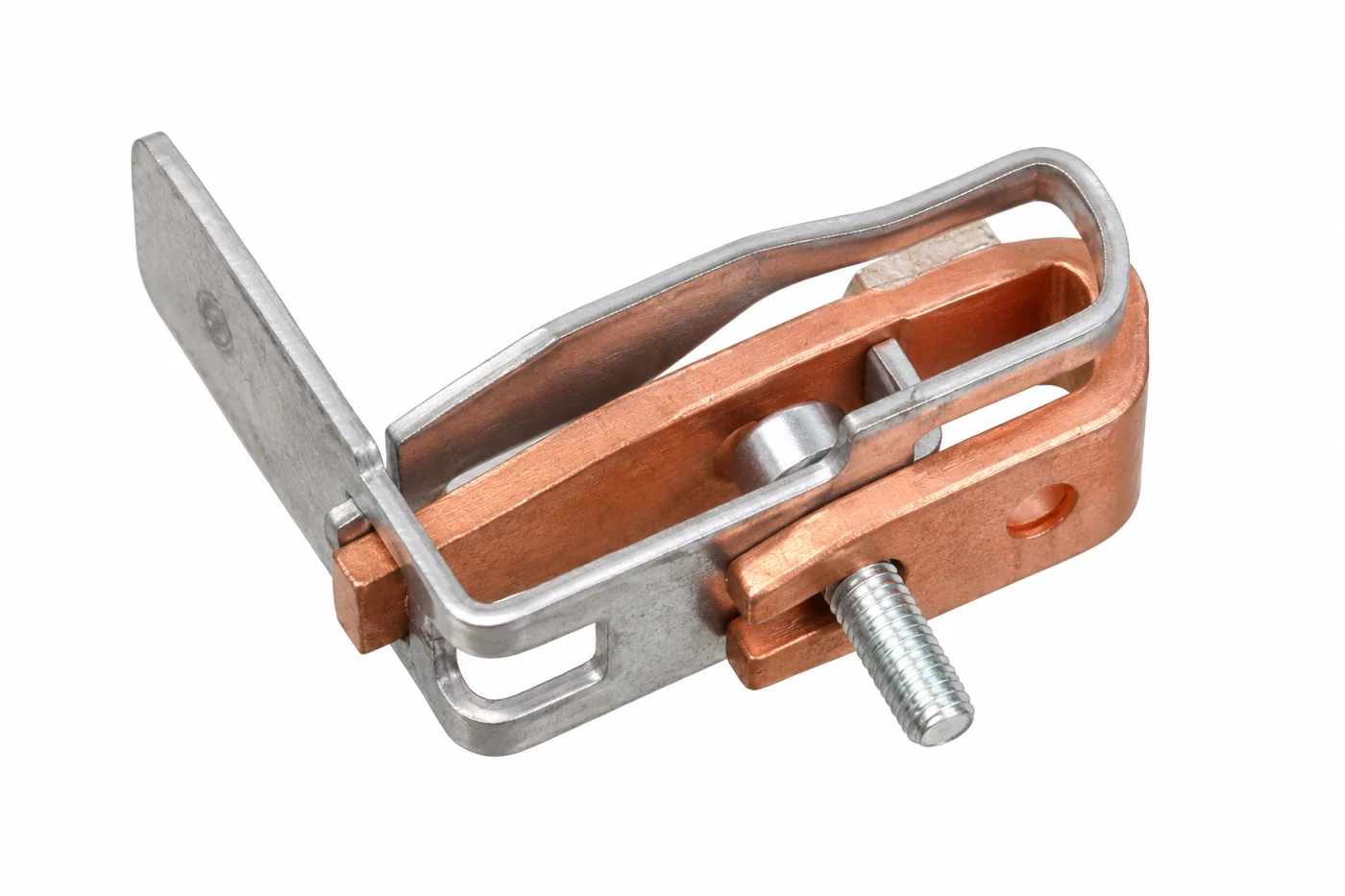
접촉저항·전압강하와 발열 위치
계측 경계와 전류 병목
단자 간 저항이 증가했다는 결과만으로 은합금 접촉면을 불량 원인으로 지목할 수는 없습니다. 전류는 고정 단자, 접합부, 양쪽 접점 팁, 실제 맞댐 계면, 가동 도체와 출력 체결부를 통과합니다. 전체 저항을 낮추려면 이 직렬 경로 가운데 손실이 집중되는 위치부터 찾아야 합니다.
접촉면에서는 미세 돌기의 실제 맞닿은 영역으로 전류가 몰리면서 수축저항이 생깁니다. 산화물·황화물·유기 오염에 의한 피막저항도 더해지며, 두 성분은 접촉력과 표면 상태의 영향을 받습니다. 반면 도체 몸체의 저항은 재료 전도도와 길이·단면에 좌우되므로, 접점 소재만 바꾸는 대책으로는 긴 가동 암의 손실을 제거할 수 없습니다.
4단자 켈빈 측정은 전류 공급선과 전압 감지선을 분리하여 공급 리드의 전압강하를 제외하는 방법입니다. 감지점 사이의 팁 몸체와 접합부까지 없어지는 것은 아닙니다. 도면에 감지점과 포함 부위를 표시하고, 외부 단자 간 전체 저항과 국부 구간 저항을 구별해야 설계 변경 전후를 비교할 수 있습니다.
구간별 손실 비교
다음은 감지점에 접근할 수 있는 단일 전류 경로의 검증용 조립체를 가정한 계산 예입니다. 일정한 DC 80 A가 흐르고 열적 상태와 접촉력이 안정된 시점에, 입력 단자부터 출력 단자까지 네 구간의 전압강하가 아래와 같다고 가정합니다. 특정 제품의 실측값·정격·합격 기준이 아니며, 표의 저항은 해당 전압강하를 80 A로 나눈 값입니다.
| 전압 감지 구간 | 전압강하 | 구간 저항 | 발생 손실 |
|---|---|---|---|
| 입력 단자–고정 팁 뒷면 | 12 mV | 0.15 mΩ | 0.96 W |
| 고정 팁 뒷면–가동 팁 뒷면 | 32 mV | 0.40 mΩ | 2.56 W |
| 가동 팁 뒷면–가동 도체 끝 | 16 mV | 0.20 mΩ | 1.28 W |
| 가동 도체 끝–출력 단자 | 4 mV | 0.05 mΩ | 0.32 W |
| 전체 경로 | 64 mV | 0.80 mΩ | 5.12 W |
두 팁 뒷면 사이의 32 mV에는 실제 접촉 계면과 양쪽 팁 몸체가 함께 포함됩니다. 따라서 0.40 mΩ을 순수한 계면 저항으로 단정하면 안 됩니다. 몸체 성분을 분리하려면 재료·형상을 반영한 별도 평가가 필요합니다.
손실 증가 위치의 판별
같은 80 A에서 전체 전압강하가 96 mV가 되면 총손실은 7.68 W로, 기존보다 2.56 W 증가합니다. 증가분 32 mV가 팁 사이에 생겼다면 표면 상태·접촉력을, 가동 도체 구간에 생겼다면 도체 단면·균열·해당 접합부를 우선 조사합니다. 총저항은 같아도 개선 대상과 열이 집중되는 위치는 다릅니다.
구간별 전압강하의 합과 전체 전압강하가 맞지 않으면 감지점 중복·누락, 시간차에 따른 온도 변화와 계측 오프셋부터 확인합니다. 병렬 우회 경로가 있으면 전압강하의 합이 맞더라도 각 구간에 같은 80 A가 흐른다는 전제를 사용할 수 없으므로 구간 전류를 별도로 확인합니다. 발열 위치를 고른 뒤 온도 이력과 대조해야 하며, 2.56 W 증가를 곧바로 특정 온도상승으로 환산할 수는 없습니다. 밀폐 제품을 임의로 가공해 만든 측정창은 본래 방열과 기구 조건을 바꿀 수 있습니다.
저항 변화와 측정 자극
표면을 보존해야 하는 고장 분석에서는 저수준 측정을 먼저 하고, 실제 통전 전류의 전압강하는 별도로 기록합니다. 높은 시험 전압은 피막을 뚫고 큰 전류는 미세 접촉점을 연화시켜, 측정 과정 자체가 저항을 낮출 수 있습니다. 드라이서킷의 개방전압 20 mV 이하·단락전류 100 mA 이하 조건은 대표적인 방법 예이며, 모든 전력접점의 공통 검사조건은 아닙니다.
μV 수준에서는 이종 금속 접속부의 열기전력이 결과에 섞입니다. 전류 반전이나 무전류 오프셋 보정을 사용하되, 측정 주기 중 온도 드리프트와 계측기의 안정화 시간을 관리해야 합니다. AC에서는 전압·전류 실효값의 비에 리액턴스가 포함될 수 있으므로 위상을 반영한 저항성 성분과 유효전력으로 발열을 판단합니다.
수명 전후 비교에는 감지점, 부품 온도와 시험 자극을 맞추고, 각 측정의 누적 개폐 횟수와 직전 동작 상태를 별도로 기록합니다. 순동의 온도계수를 전체 접점 경로에 일괄 적용하면 피막·접합부 변화까지 도체 온도 변화로 오인할 수 있습니다. 낮은 값 하나보다 같은 조건에서 재현되는 구간별 변화가 원인 판정에 더 유용합니다.
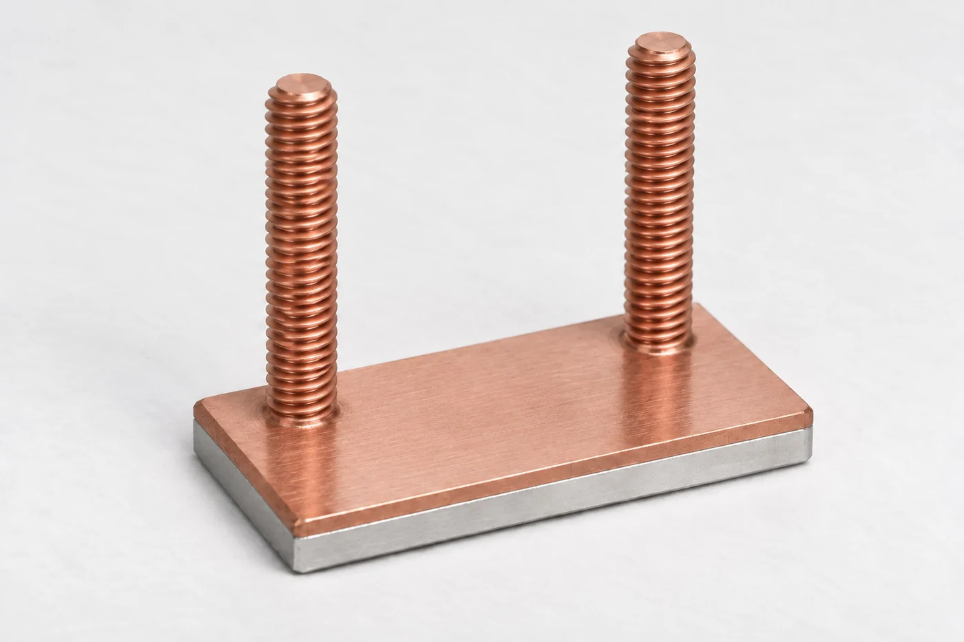
접촉력·바운스·개방기구의 균형
접점을 세게 누르면 저항이 낮아질 수 있지만, 그것만으로 개폐 안정성이 완성되지는 않습니다. 접촉력은 닫힌 뒤의 정적 수치인 동시에, 충돌하고 튀고 다시 눌리는 동안 계속 달라지는 힘입니다. 최초 접촉에서 힘을 만드는 과정과 개방 때 그 힘을 해제하는 과정을 함께 설계해야 합니다.
스프링 하중과 실제 접촉력
코일의 흡인력, 스프링 반력, 접점면에 전달되는 힘은 같은 값이 아닙니다. 힘이 전달되는 지점과 지렛대 관계, 가동부의 가속, 탄성 변형과 마찰에 따라 달라집니다. 두 접점을 가진 브리지에서도 총하중만 측정하면 좌우 높이 차이로 한쪽에 집중된 하중을 놓칠 수 있습니다.
접촉 여유는 최초 접촉 이후 기구가 더 이동하면서 접촉력을 형성하는 이동량입니다. 접촉 여유를 확보하면 마모와 치수 편차에 대응할 수 있지만, 스프링 강성·변형 형상·구동 위치가 다르면 같은 이동량이 다른 힘과 충돌을 만듭니다. 초기 접점 높이와 간극, 닫힘 위치의 하중을 각각 관리해야 하는 이유입니다.
정적 힘–변위 검사는 조립 기준점과 접점별 측정 위치를 고정하여 최초 접촉 위치, 추가 이동 구간의 하중, 최종 닫힘 상태를 기록합니다. 신품과 마모품의 곡선을 비교하면 접촉 여유 소모와 잔류 하중 변화를 나눠 볼 수 있습니다. 그러나 이 곡선만으로 바운스 횟수나 실제 개방속도를 예측했다고 주장해서는 안 됩니다.
접촉 여유와 바운스의 상충
접촉 여유를 늘리는 조정이 바운스를 악화시키는 경우도 있습니다. 카드로 탄성 접점 스프링을 구동하는 한 릴레이 연구에서, 기준 대비 접촉 여유를 63%·100%·150%로 바꿨을 때 실측 바운스 시간은 각각 1.34·1.64·2.13 ms였습니다. 이는 해당 구조의 비교 결과이지 권장 이동량이나 일반적인 증가 법칙은 아닙니다.
같은 연구의 계산과 실측에는 약 20~30% 수준의 차이가 있었으므로, 모델은 상대 비교에 활용되었습니다. 설계자는 ‘힘을 늘린다’는 한 가지 목표보다 어떤 변화가 최초 충돌 속도와 탄성 진동, 안정적으로 눌리는 시점을 바꿨는지 확인해야 합니다. 좋은 계산 곡선도 실제 접점 파형과 대조되지 않으면 승인 근거가 부족합니다.
측정 대상을 아마추어에만 두는 것도 주의가 필요합니다. 아마추어가 카드나 푸셔를 거쳐 유연한 접점 암을 움직이는 구조에서는 두 부품이 같은 속도로 움직이지 않습니다. 구동부가 빠르게 복귀해도 접점 암의 휨과 진동 때문에 실제 접점 분리가 늦을 수 있으므로, 변위 계측의 대상과 속도 계산 구간을 명시합니다.
개방 여유와 고장전류 반발
개방기구는 정상 접촉력을 해제하는 것뿐 아니라 실제 사용 중 생긴 약한 결합을 분리할 여유도 필요합니다. 다만 분리력을 높인다는 이유로 스프링을 무조건 강하게 하면 코일의 흡인 여유, 접촉 충돌과 복귀 시작 시점이 바뀝니다. 보호회로가 코일 전류를 천천히 줄이는 경우에는 기구가 움직일 때 남아 있는 자기력도 함께 작용합니다.
검증에서는 개방 명령, 코일 전류 감소, 실제 접점 분리, 부하 전류 소멸을 구분하여 기록합니다. 개방 시작이 늦은 문제와 시작은 빨라도 이후 속도가 떨어지는 문제는 수정할 부위가 다릅니다. 평상시 평균 복귀시간이 같다는 이유만으로 약한 용착을 분리하는 능력도 같다고 판단할 수 없습니다.
고장전류에서는 충돌 바운스와 별도의 접점 들림이 발생할 수 있습니다. 도체 배치와 전류 집중이 만드는 전자반발이 커지면 유효 접촉력이 줄고, 유지 능력을 넘으면 틈과 아크가 생깁니다. 같은 형상을 가정한 주요 반발 항이 순간 전류의 제곱에 따라 커진다는 점 때문에 평균 전류보다 실제 피크와 지속시간이 중요합니다.
이 경우 개선 대상은 스프링만이 아닙니다. 전류 경로의 형상, 접점별 하중 분배와 보호기기의 제한 피크·차단 시간을 함께 검토해야 합니다. 통전 중 저항을 낮춘 수정이 단락 후의 기계적 건전성까지 보증하지는 않으므로, 정상 내구성과 지정 보호기기 조합의 고장 시험을 분리하여 승인합니다.
접점 소재·판접점·접합 공정의 설계
고장품에 침식이 보인다는 이유만으로 은 함량이나 접점 두께부터 바꾸면 원인이 남을 수 있습니다. 작동면이 반복해서 녹는 문제, 전이물이 걸리는 문제, 팁 아래 접합부가 발열하는 문제는 서로 다른 재료·공정 판단을 요구합니다. 먼저 손상의 위치와 시작 단계를 특정한 뒤 소재 등급과 구조를 연결해야 합니다.
손상 형태와 접점재료
AgNi는 은의 도전성과 니켈 분산상의 특성을 함께 활용하는 계열입니다. AgSnO₂는 산화물 분산을 이용해 내용착성과 아크 소모를 조정하지만, 산화물 함량·분포와 첨가제, 제조 경로에 따라 저항과 가공 거동이 달라집니다. AgW는 내아크성 측면의 장점과 함께 저항·접촉력·접합 적합성을 별도로 검토해야 합니다.
따라서 재료 계열명은 선택의 출발점이지 대체 승인서가 아닙니다. 같은 명칭이라도 실제 공급 등급, 조직과 경도, 성형 후 상태가 다르면 접촉 면적과 마모가 바뀔 수 있습니다. 한 재료의 낮은 소모량을 다른 부하의 긴 개폐 수명으로 바꾸어 해석하지 않습니다.
| 주요 손상 위치 | 재료·공정 검토 | 승인에 필요한 대응 데이터 |
|---|---|---|
| 작동면의 용착·전이 | 접점 등급, 상대재, 표면 형상과 접촉력 | 같은 부하 파형의 개방 실패와 표면 변화 |
| 팁 아래 접합부 | 접합층 연속성, 미접합·기공, 캐리어 변형 | 구간 전압강하·온도와 대표 단면 |
| 접점 암·브리지 | 재질·단면, 성형 상태, 접점 높이와 정렬 | 힘–변위, 좌우 하중과 고온 동작 |

작동면과 영구 접합부의 구별
판접점은 판상으로 만든 접점 팁의 형상을 가리키며 그 명칭만으로 단일 재료인지 복합층인지 결정되지 않습니다. 솔리드는 접점 몸체가 같은 접점재료 조성으로 이루어진 구조입니다. 클라드는 작동면의 접점재료와 이를 지지하는 구리계 몸체를 결합한 구조로, 얇은 표면 도금과 구분해야 합니다.
팁과 캐리어 사이의 영구 접합부는 접촉·분리를 반복하는 두 작동면과 목적이 반대입니다. 작동면에는 적합한 분리 성능이 필요하지만, 내부 접합부는 기계적으로 유지되면서 전류와 열을 안정적으로 전달해야 합니다. 접점재료층, 접합용 뒷면층, 브레이징층과 캐리어를 한 재료로 취급하면 원가와 검사 범위도 잘못 정해집니다.
리벳 조립에서는 샹크·홀의 적합성과 성형된 체결부, 팁의 기울기 및 접촉면 변형을 구분해 봅니다. 접합형 판접점에서는 준비된 면과 접합재, 가압 위치, 열이 들어가는 경로가 중요합니다. 충분히 붙어 보이더라도 전류가 통과하는 유효 접합 면적과 접점 높이가 유지되는지는 별도 확인이 필요합니다.
공정 파형과 단면의 교차검증
은 접점 요소와 구리 캐리어를 접합한 50 Hz 저항브레이징 연구에서는 실효전류 7,100 A·200 ms·전극 가압력 480 N에서 접합 중 전압강하를 기록했습니다. 별도의 실효전류 6,750 A·300 ms·480 N 조건에서는 단면의 접합층에 더 많은 기공이 나타나 공정 후보에서 제외되었습니다. 외관이나 강도가 만족스러울 수 있어도 내부 결함을 배제할 수 없다는 사례입니다.
이 전류·시간·하중은 해당 재료와 형상, 접합재 및 설비의 연구 조건입니다. 다른 은합금, 팁 두께나 전원 방식에 그대로 적용할 수 없으며, 논문이 모든 제품의 허용 기공률을 제시한 것도 아닙니다. 중요한 점은 설정 전류 한 값이 아니라 실제 전류·전압의 이력, 가압과 단면 결과를 연결해 공정 범위를 정했다는 데 있습니다.
양산 승인에서는 접합 강도, 전기적 경로와 기하학적 건전성을 분리하여 확인합니다. 대표 단면으로 접합층의 연결 상태와 결함 위치를 보고, 정의한 감지점 사이의 전압강하 및 통전 온도와 대조합니다. 강도 시험만 통과한 부품이나, 전체 저항이 낮다는 이유로 특정 접합부 검토를 생략한 부품은 서로 다른 미확인 위험을 남깁니다.
발주 도면에는 정확한 소재 등급과 허용 대체 범위, 작동면의 유효 재료 두께, 캐리어 재질·두께, 접합 방식, 접점 높이와 정렬 기준을 묶어 남깁니다. 접합 조건이나 소재 공급원을 바꿀 때에는 치수뿐 아니라 해당 변경이 영향을 주는 저항·온도·힘과 개폐 내구성까지 재승인 범위를 정합니다. 접점 단품과 접합 완료 부품의 공급 책임도 이 단계에서 구분해야 합니다.
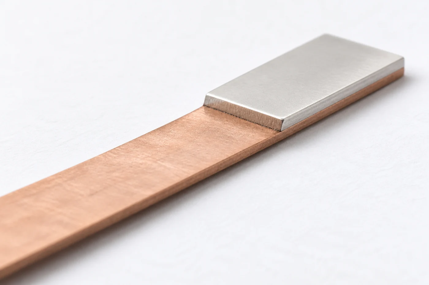
열적 설치조건과 전류 정격
통전 정격과 사용범주
전류 정격을 검토할 때는 정상 통전, 부하 투입·차단, 고장전류 통과를 먼저 분리합니다. 접점을 닫은 채 온도상승이 안정적이었다는 결과는 큰 돌입전류를 받아들이거나 유도성 전류를 끊을 수 있다는 보증이 아닙니다. 전압과 전류의 개별 최댓값을 조합해 사용 가능한 개폐 용량을 만드는 것도 잘못된 해석입니다.
전자접촉기의 Ith는 외함이 없는 자유공기 조건에서 정의되는 관례 열전류이고, Ie는 정격 사용전압·사용범주 등 지정 조건의 정격 사용전류입니다. 실제 외함, 배선, 동시 통전 극수와 인접 발열원이 정격 평가 조건과 달라지면 설치 상태의 온도상승을 다시 확인해야 합니다. 다극 동시 통전 자체가 정격을 무효로 만드는 것은 아니며, 무엇이 원래 시험에 포함되었는지 대조하는 것이 핵심입니다.
| 검토 조건 | 접점에 가해지는 부담 | 정격에서 확인할 항목 |
|---|---|---|
| 지속 통전 | 닫힘 상태의 저항 손실과 축열 | 배선·주위온도·외함 조건, 허용 온도상승 |
| AC-1 | 비유도성 또는 약한 유도성 부하의 개폐 | 해당 전압의 사용전류와 개폐 조건 |
| AC-3 | 농형 유도전동기 기동과 정상 운전 중 차단 | 기동·운전 조건과 전기적 내구성 |
| DC·인칭·역전 제동 | 지속 아크 또는 큰 전류의 반복 차단 | 해당 부하의 별도 정격·사용범주 |
AC-3는 모터가 돌고 있다는 이유만으로 모든 조작을 포괄하지 않습니다. 짧게 켰다 끄는 인칭이나 역전 제동은 기동전류에 가까운 전류를 반복 차단할 수 있으므로 실제 운전 순서에 맞는 사용범주를 적용해야 합니다. DC 부하도 같은 전압·전류의 AC 값에서 환산하지 않고 제조사의 해당 부하 정격으로 검토합니다.
방열 경로와 온도 여유
접점에서 생긴 열은 팁과 접합부를 거쳐 구리 캐리어·단자·케이블 또는 PCB 동박으로 퍼집니다. 케이블은 전기적 연결이면서 열을 빼내는 부품이므로 단면뿐 아니라 길이, 단자 체결 상태와 주변 열접촉도 시험조건에 포함해야 합니다. 굵고 짧은 시험 배선으로 낮게 나온 온도를 실제 장치의 보증 온도로 바꿀 수는 없습니다.
부품 주위온도는 제어반 밖의 실내 온도가 아니라 그 부품에 인접한 공기의 온도입니다. 하우징을 닫고 인접 부하를 함께 운전한 상태에서 단자·접합부·코일 등 감시 위치의 온도 이력을 기록합니다. 열적 안정화는 정해진 몇 분이 아니라 적용 시험법의 안정화 기준으로 판단하고, 각 위치의 부품 온도와 주위온도 대비 상승분을 별도로 판정합니다.
같은 전력 손실에서도 열이 빠져나가는 경로가 나쁘면 온도는 더 높아집니다. 반대로 방열만 개선해 온도가 낮아졌다고 불안정한 접합부의 저항까지 개선된 것은 아닙니다. 전압강하와 온도를 함께 보면 전류 경로 개선이 필요한지, 배선·배치·통풍을 바꿔야 하는지 구별할 수 있습니다.
디레이팅은 제품의 온도별 전류 곡선과 실제 설치조건을 연결하는 작업입니다. 임의로 정격의 80%를 택하는 대신 최고 주위온도, 배선, 동시 발열과 수명 후 저항 변화를 반영해 여유를 확인합니다. 초기 시료의 평균 온도만으로 양산품 전체의 온도한도를 보증해서는 안 됩니다.
열–기계 결합과 고온 재투입
고정된 DC 전압으로 구동하는 구리 권선은 뜨거워지면 저항이 증가하고 전류가 감소합니다. 권선 온도가 20°C에서 80°C로 오른다는 계산 예에서는 저항이 약 24% 늘고 전류는 약 19% 줄어듭니다. 이는 코일 자체 온도와 일정 전압을 가정한 전기적 계산이며, 자기력이나 접촉력이 같은 비율로 감소한다는 뜻은 아닙니다.
구동 여유가 부족해 가동 철심이 끝까지 착좌하지 못하면 접점이 연결되어도 충분한 접촉력이 형성되지 않을 수 있습니다. 이 상태의 국부 발열과 큰 투입전류가 겹치면 미세 용착에 불리하므로, 충분히 가열된 장치의 재투입을 실제 최저 코일 단자전압에서 확인해야 합니다. AC 코일이나 전류 제어·절전 구동에 단순한 DC 고정전압 계산을 그대로 적용하지 않습니다.
장기 고온 노출은 전류를 전달하는 스프링재의 응력완화에도 영향을 줍니다. 같은 변위를 유지해도 시간이 지나 하중이 감소할 수 있으므로, 초기 경도만이 아니라 소재 등급·조질·사용 온도에서의 하중 유지와 마모 후 접촉 여유를 함께 확인합니다. 낮은 초기 저항이 장기 운전에서도 유지되는지는 열·저항·잔류 접촉력의 연결로 판단해야 합니다.

부하·코일 보호회로와 고온 재기동
접점 보호회로는 어디에 연결하는지에 따라 해결하는 문제가 달라집니다. 부하 쪽의 보호소자는 투입 전류나 차단 시 에너지 흐름을 바꾸고, 코일 쪽의 보호소자는 구동소자의 과전압과 접점기구의 복귀 운동에 영향을 줍니다. 둘을 한꺼번에 ‘서지 억제’로 묶으면 한쪽 파형을 개선하면서 다른 쪽의 개폐 부담을 키울 수 있습니다.
용량성 부하와 프리차지
입력 커패시터가 있는 회로에서는 접점을 닫기 직전의 전원과 커패시터 사이 전압 차이가 중요합니다. 여기에 전원 내부와 배선, 접점 및 충전 경로의 임피던스가 더해져 돌입 파형이 정해집니다. 모터가 연결된 장치라도 해당 접점이 인버터의 입력단을 개폐한다면 모터 자체의 기동 특성만으로 부하를 설명할 수 없습니다.
프리차지는 저항 등 제한 경로를 통해 먼저 충전한 뒤 주접점을 닫는 방식입니다. 주접점이 받아야 할 잔여 충전 부담을 줄이는 것이 목적이므로, 고정 지연시간만 확인하지 말고 실제 전압 상승과 남은 전압 차이를 감시해야 합니다. 충전 중 하위 회로가 전력을 계속 소비하면 예상했던 전압에 도달하지 못할 수도 있습니다.
충전이 너무 느리면 제한 저항, 전원 강하와 잔류 부하를 검토하고, 예상보다 빠르면 경로 우회나 초기 잔류전압을 구별합니다. 시간 초과 뒤 반복 재시도를 허용할 때에는 제한 저항이 충분히 식지 않은 상태의 누적 펄스 부담도 확인합니다. 정격 소비전력만으로 짧은 충전 펄스를 견디는지 판단하지 말고 해당 부품의 펄스 에너지·시간 및 반복 조건과 대조합니다.
코일 클램프와 실제 개방 운동
DC 코일 전원을 끄면 저장된 자기 에너지 때문에 구동소자 양단에 높은 전압이 생길 수 있습니다. 병렬 다이오드는 이를 낮게 제한하지만 코일 전류가 순환하는 시간을 늘릴 수 있습니다. 남은 자기력 때문에 NO 접점의 복귀가 늦어지면, 차단 아크뿐 아니라 약한 결합을 분리하는 과정도 영향을 받습니다.
제너·TVS 등을 이용해 더 높은 전압에서 클램프하는 방식은 전류 감쇠를 빠르게 할 수 있지만, 구동소자가 받는 전압이 높아지고 보호소자의 펄스 부담도 달라집니다. 명목 제너 전압만 비교하지 말고 실제 펄스 전류에서의 클램프 전압, 공차, 에너지와 구동소자 내압을 함께 확인합니다. 내장 보호회로나 절전 구동이 있는 제품에는 제조사가 허용한 연결을 적용해야 합니다.
회로 변경의 효과는 코일 전류가 빨리 줄었다는 사실로 끝나지 않습니다. 실제 접점이 언제 움직이고 얼마나 빨리 분리되는지, 부하 전류가 언제 소멸하는지까지 비교해야 합니다. NC 접점에서는 복귀가 곧 투입 동작이므로, 느린 복귀가 충돌을 줄이는 경우도 있어 NO에 맞춘 처방을 그대로 옮길 수 없습니다.
차단 에너지와 재투입 조건
DC 유도성 부하를 가로질러 연결한 다이오드나 클램프는 코일 보호와 다른 경로에서 작동합니다. 부하 전류가 접점 밖의 경로로 감쇠하도록 하면서 부하의 전압과 전류 소멸시간을 바꿉니다. 전압을 낮게 제한하면 솔레노이드 등 부하의 해제가 늦어질 수 있으므로, 접점 보호와 장치의 동작 순서를 함께 확인해야 합니다.
RC 스너버도 차단 파형만 보고 승인하면 안 됩니다. 커패시터에 저장된 에너지가 다음 투입 때 접점을 통해 빠르게 방전될 수 있으므로, 저항의 전류 제한과 펄스 정격을 확인합니다. 배치에 따른 꺼진 상태의 누설전류, 커패시터의 전압·AC 적합성도 실제 회로에서 검토합니다.
고온 재기동은 이러한 보호 대책의 약점을 드러내는 조건입니다. NTC 제한기는 가열되어 저항이 낮아진 상태에서 다시 켜지면 냉간 때와 같은 돌입 제한을 제공하지 못할 수 있습니다. 코일 온도와 전원 전압 강하도 동작 여유를 바꾸므로, 충분히 가열된 운전 뒤의 짧은 정지·재투입을 별도 조건으로 남깁니다.
변경 전후 시험은 같은 부하 상태와 전원·배선, 주위온도에서 비교하고, 투입과 차단을 모두 기록합니다. 돌입 피크만 낮아졌는데 개방 지연이나 보호소자 온도가 증가했다면 설계가 완결된 것이 아닙니다. 정상 반복뿐 아니라 충전 실패, 시간 초과와 재시도에 대한 동작도 사전에 정하여 주접점이 불완전한 상태로 투입되지 않도록 합니다.
검증 순서와 도면·구매 승인
원상태와 계측 반복성
고장품은 세척·분해·강제 개방 전에 원상태를 남겨야 합니다. 무전압과 잔류전하 방전을 확인한 뒤 부품 식별, 사용 이력, 고장 직전 투입·차단 파형과 표면·기구 상태를 연결합니다. 고장을 재현하겠다는 이유로 먼저 큰 전류를 흘리면 피막이나 용착부가 바뀌어 최초 원인이 사라질 수 있습니다.
개발 시료는 접점재료 로트, 성형·접합 조건, 캐리어와 코일 사양까지 추적되도록 구분합니다. 수명 추적 시료와 파괴 단면 분석·고장전류 시험 시료도 계획 단계에서 나눠야 합니다. 한 번 분해하거나 접촉력을 조정한 시료의 이후 결과를 조작하지 않은 시료와 같은 이력으로 합치지 않습니다.
계측 반복성과 접점 자체의 반복 변동도 별개입니다. 같은 닫힘 상태에서 읽기만 반복한 값, 감지 리드나 지그를 다시 설치한 값, 접점을 개폐한 뒤의 값을 분리하면 계측계·설치·접촉 상태의 영향을 구별할 수 있습니다. 기준 저항 점검과 시험 전후의 계측계 확인을 병행하고, 저항차가 측정 불확도와 비슷하면 개선이 입증되었다고 단정하지 않습니다.
실부하 검증과 실패 기록
시험 순서는 초기 상태를 보존하는 계측에서 시작해 열평형과 실제 개폐 부담으로 확장합니다. 아래는 시험 목적을 연결하는 실무 구성 예이며 특정 규격의 정해진 순서를 대신하지 않습니다. 시료 배정, 중간 검사 간격과 판정 기준은 시험 전에 확정해야 결과를 유리하게 골라 해석하는 일을 막을 수 있습니다.
| 단계 | 고정할 조건·기록 | 다음 단계의 판단 |
|---|---|---|
| 초기 상태 | 정의한 저수준 저항, 감지점, 접촉력·간극·접촉 여유 | 초기 불량과 시료 편차, 측정 재현성 분리 |
| 지속 통전 | 실제 외함·배선·코일 구동, 구간 전압강하와 온도 이력 | 발열 위치, 안정화, 위치별 온도 여유 확인 |
| 실부하 개폐 | 전원 임피던스, 돌입·차단 파형, ON/OFF 시간, 고온 재투입 | 바운스·아크·불개방의 발생 단계 식별 |
| 수명 중간·종료 | 동일 조건의 저항·온도, 개방·절연·마모·잔류 접촉력 | 성능 유지, 열화 속도와 최초 실패 시점 판정 |
시료의 초기 평균값과 종료 평균값만 비교하면 중간에 발생한 불개방이나 불안정 접촉이 가려집니다. 합격 항목에는 위치별 허용온도, 정의된 자극에서의 저항 또는 저항 변화, 개방 실패, 절연 상태와 요구 개폐 횟수를 각각 둡니다. 경계값에 가까운 결과의 재시험·보류 처리와 계측 불확도 반영 방식도 미리 정합니다.
시료 이력과 신뢰성 해석
저항과 온도는 가능한 한 같은 시료의 같은 감지점에서 중간 이력을 추적하되, 냉간 기준 측정과 가열 상태의 값을 섞지 않습니다. 한 시료의 수십만 회 동작은 수십만 개의 독립 시료가 아니며, 긴 시험 한 번이 제조 로트 간 산포를 대신하지도 않습니다. 시료 수·로트 수·시험 종료 조건과 실패 시점을 함께 보고해야 신뢰성 해석의 범위가 분명해집니다.
종료 시점까지 고장 나지 않은 시료는 그 이후 수명을 알 수 없는 관찰 종료 데이터로 남깁니다. 무고장 결과만으로 불량률 0%를 선언하거나, 높인 온도·전류의 시험시간을 검증된 가속모델 없이 정상 사용연수로 바꾸지 않습니다. 용착을 외력으로 분리한 뒤의 동작은 원인 연구용 이력이며 정상 수명에 합산하지 않습니다.
고전압·고장전류 시험은 보호 인클로저·원격 조작·방전 확인을 갖춘 적격 환경에서 수행합니다. 단락 협조는 실제 보호기기 조합의 별도 검증 항목이며, 통전·개폐 시험의 합격으로 대체할 수 없습니다. 고장품의 수동 분리를 정상 복구나 재사용 승인으로 취급하지 않습니다.
제작 사양과 변경 승인
도면에는 접점의 정확한 소재 등급과 솔리드·클라드 구조, 작동면 형상·유효 두께, 접합 방식, 캐리어 재질·단면을 명시합니다. 검사 부속서에는 감지점과 시험 자극, 온도 조건, 접촉력·접촉 여유의 측정 상태를 함께 둡니다. 부하 파형·배선·코일 구동·목표 수명이 빠지면 치수가 같은 부품끼리도 개폐 성능을 동등하게 비교하기 어렵습니다.
은 함량, 성형 조건, 접합층, 캐리어 두께 또는 코일 보호회로가 바뀌면 어떤 고장 경로에 영향을 주는지에 따라 재검증 범위를 정합니다. 접점 단품, 접합 완료 캐리어, 완성 개폐 장치 중 공급·승인 범위를 분명히 하고 비교 시료의 변경 이력을 남깁니다. 양산 승인은 낮은 저항값 하나가 아니라 규정된 열·개폐·절연 성능의 유지와 제조 편차에 대한 근거로 판단해야 합니다.
Contact Welding and Heating: From Failure Diagnosis to Material, Process and Life Design
Contact welding cannot be explained simply as contacts sticking because the current is too high. Repeated impact during closure, localized heating at small conducting spots, the metallic bridge and arc formed during separation, and the separating force of the mechanism interact. Failure to open can occur even with a low terminal temperature or low initial contact resistance.
The starting point for a remedy is not a material substitution. It is to separate when damage develops from where electrical power is dissipated. Connecting load waveforms and contact motion with voltage drops along the current path and joint quality enables resistance to contact welding and temperature-rise control to be designed together.
Inrush coinciding with contact bounce
Local losses and heat-removal paths
Metallic bridges, arcs and opening margin
Separating the Symptom from the Evidence
A load remaining energized after an opening command is a symptom, not a cause. First distinguish metallic welding, mechanical interlocking caused by transferred material, residual coil drive and deformation of the moving mechanism. Temporary recovery after replacing a contactor does not establish that contact material caused the original failure.
Detection Time and Formation Time
A small bond formed during closure can remain undetected throughout a long carrying period and appear only at the next opening command. Contacts that opened normally can also suffer new damage at the next closure when bounce coincides with inrush. Recording only the interruption immediately before a failure can therefore lose the initiating event.
Use the control command, coil-terminal voltage and current, load current and voltage across the contacts as the timing references. Add moving-part displacement on the same time base where feasible. For a non-latching relay, persistent coil current after command removal calls for a different investigation from contacts remaining closed after that current has decayed sufficiently.
A latching relay is designed to retain its state when coil power is removed. For that product, do not interpret power removal alone as an opening command; first verify that the specified reset input was actually applied.
| Initial symptom | Evidence needed to classify the cause | Avoid a premature change |
|---|---|---|
| Repeated reopening immediately after closure | Coincidence of contact-voltage pulses, load current and coil-voltage sag | Distinguish impact bounce from supply-related chatter before changing only the material. |
| Increasing voltage drop while closed | Non-overlapping measurements across contact, carrier, joint and termination regions | Do not treat total terminal resistance as contact-interface resistance. |
| Current persists after the opening command | Coil decay, mechanism motion, the as-found condition and mating-pair arrangement before separation | Do not force the contacts apart before isolation and as-found documentation. |
| Momentary contact lift under fault current | Instantaneous peak, lift timing, arc duration and protective-device clearing history | Do not use an ordinary carry rating to approve fault-current duty. |
Preserving the As-Found Condition
First isolate the equipment safely and verify absence of voltage, including stored-energy sources. Separation, cleaning, polishing and retightening change transferred material, fastening evidence and surface films. Do not perform them before initial documentation. Mark the orientation and mating pair, and preserve the spatial relationships between both contact surfaces, terminations and joints.
Corresponding projections and depressions can support investigation of material transfer and mechanical interlocking. Surface colour or rough marks alone cannot establish the welding temperature, alloy composition or time of formation. Add cross-sections, compositional analysis and process records as needed. Compare these with the causes indicated by waveforms and location-specific loss measurements.
Comparison with unused parts from the same lot, preceding sound specimens and samples before and after a condition change is more useful than the appearance of one failed part alone. First establish whether the lot, actual conductors, coil suppression and initial load condition were equivalent. A failure to open that affects a safety function must not be treated by separating the contacts for temporary reuse. Review the equipment’s protection and fault-detection design as well.
Contact Welding During Making and Breaking
Contact welding does not require two entire contacts to melt together. A small metallic bond within the interface can prevent opening if normal release motion cannot break it. Even when a weak bond separates during release, delayed opening or transferred surface material may appear first.
Microscopic Current Paths and Molten Bridges
At first touch, the entire visible contact face does not accept current simultaneously. A few surface asperities connect first, concentrating current into narrow paths. If current builds faster than contact force develops, these initial conducting spots can experience greater thermal stress.
Distinguish resistive heating while closed from arc heating during separation. Resistance losses in small conducting spots can cause local softening or melting. During bounce or intentional opening, the narrowing molten region may remain as a bridge between the separating surfaces before it ruptures.
A molten bridge is neither ordinary solid contact nor a fully interrupted empty gap. Discharge can continue in released metal vapor immediately after rupture. Current therefore need not disappear when contact motion begins. High-speed observations of pure-metal contacts have also revealed a bridge rupturing and then reconnecting during separation.
That research does not directly establish the welding threshold or endurance of a particular silver-alloy contact. Its practical lesson is that separation should not be interpreted solely as a binary closed-to-open signal. Metallic connection, arc conduction and final current interruption can end at different times.
Recontact and Failure at the Next Opening
Making bounce briefly repeats contact and separation. If surfaces heated during separation bond when pressed together again, the following steady-conduction period may appear normal. The weld may only become evident at the next opening command.
Arc duration alone does not determine the result of recontact. Current during that interval, the heated location and area, residual molten material, renewed impact and subsequent release motion all contribute. Arc energy requires the contact voltage and current to be evaluated together over the relevant interval. Rated voltage multiplied by peak current and total bounce duration is not an equivalent measurement.
Repeated switching also changes the starting condition of the next operation. A mound on one side and a depression on the other can move the conducting location. Wear can consume contact follow. A low resistance reading does not establish the absence of these geometric and dynamic changes.
Waveforms and Actual Separation
Failure reproduction aligns load current, contact voltage, coil drive and accessible actual contact displacement on one time axis. Rising contact voltage while current continues is evidence to investigate arc conduction. Voltage alone, however, should not conclusively identify a molten bridge or mechanical recontact. Correlate it with displacement or observation.
An arc can bridge a narrow gap without completely interrupting load current during bounce. The absence of current-interruption pulses therefore does not prove the absence of bounce. Select bandwidth, sampling and probe common-mode performance for the phenomenon being distinguished. Manage slow normal-current records and high-speed switching waveforms as separate data streams.
The final diagnostic decision must match the stage where damage develops. Damage beginning immediately after making directs attention to inrush and first-contact motion. Current persisting well after actual separation directs attention to interruption conditions. When the moving assembly does not release, retain residual drive and mechanical obstruction as alternatives to welding.
Contact Resistance, Voltage Drop and Heat Location
Measurement Boundaries and Current Bottlenecks
An increase in terminal-to-terminal resistance does not, by itself, identify the silver-alloy contact face as the cause. Current passes through the fixed terminal, joints, both contact tips, the mating interface, the moving conductor and the output connection. Reducing total resistance starts with locating concentrated loss along this series path.
At the contact face, current crowds into the microscopic regions that actually touch, producing constriction resistance. Films of oxides, sulfides and organic contamination add resistance; both contributions are influenced by contact force and surface condition. Bulk conductor resistance instead depends on conductivity, length and cross-section, so a contact-material substitution cannot eliminate loss in a long moving arm.
Four-terminal Kelvin measurement separates current-supply leads from voltage-sensing leads to exclude supply-lead voltage drop. It does not remove tip bodies or joints between the sense points. Mark those points and the included components on a drawing, distinguishing total terminal-to-terminal resistance from local interval resistance before comparing design changes.
Comparing Loss by Interval
The following calculation assumes a validation assembly with one current path and accessible sensing locations. Suppose the four intervals from input to output show the listed voltage drops while carrying a constant DC 80 A, with temperature and contact force stable. These are not measurements, ratings or acceptance limits for a particular product; each resistance is the assumed drop divided by 80 A.
| Voltage-sensing interval | Voltage drop | Interval resistance | Power loss |
|---|---|---|---|
| Input terminal–back of fixed tip | 12 mV | 0.15 mΩ | 0.96 W |
| Back of fixed tip–back of moving tip | 32 mV | 0.40 mΩ | 2.56 W |
| Back of moving tip–end of moving conductor | 16 mV | 0.20 mΩ | 1.28 W |
| End of moving conductor–output terminal | 4 mV | 0.05 mΩ | 0.32 W |
| Complete path | 64 mV | 0.80 mΩ | 5.12 W |
The 32 mV measured between the backs of the tips includes the mating interface and both tip bodies. The resulting 0.40 mΩ is therefore not pure interface resistance. Separating the bulk contribution requires a separate evaluation that accounts for material and geometry.
Locating the Added Loss
If total drop rises to 96 mV at the same 80 A, total loss becomes 7.68 W, an increase of 2.56 W. If the additional 32 mV appears between the tips, investigate surface condition and contact force first. If it appears along the moving-conductor interval, prioritize conductor cross-section, cracks and joints within that interval; identical total resistance can call for different corrective action and produce heat in different places.
If the sum of interval drops disagrees with the overall drop, first check overlapping or omitted sense boundaries, temperature changes between readings and measurement offsets. With parallel bypass paths, agreement of summed drops does not establish that the same 80 A flows through every interval; verify interval currents separately. Compare the identified heat-generating region with its temperature history; an additional 2.56 W cannot be converted directly into a specific temperature rise. Cutting an access window into a sealed product can alter its original thermal and mechanical conditions.
Resistance Changes and Test Stimulus
When failure analysis requires preservation of the surface, make low-level measurements first and record voltage drop at operating current separately. High test voltage can rupture films, and high current can soften microscopic contact spots, lowering resistance during the measurement itself. Dry-circuit conditions such as an open-circuit voltage no higher than 20 mV and short-circuit current no higher than 100 mA are representative methods, not universal inspection conditions for all power contacts.
At microvolt levels, thermoelectric EMFs at dissimilar-metal junctions contribute to the result. Current reversal or a zero-current offset correction requires control of thermal drift during the measurement cycle and instrument settling time. For AC, the RMS voltage-to-current ratio can include reactance; assess heating from the phase-resolved resistive component and active power.
Match sense locations, component temperature and electrical stimulus before and after endurance, while separately recording the accumulated switching count and immediately preceding operating state for each measurement. Applying pure copper’s temperature coefficient to the whole contact path can misclassify film or joint changes as bulk temperature effects. Reproducible interval changes under matching conditions are more useful for diagnosis than a single low reading.
Balancing Contact Force, Bounce and Release Motion
Greater contact force can reduce resistance, but it does not by itself establish reliable switching. Contact force is both a static value after closure and a changing force during impact, rebound and renewed compression. The process that develops force at first contact must be designed together with the motion that removes it at opening.
Spring Load and Actual Contact Force
Coil attraction, spring reaction and force at the contact face are not identical. They depend on force application and leverage, moving-part acceleration, elastic deformation and friction. In a two-contact bridge, a total-load measurement can also miss unequal loading caused by contact-height differences.
Contact follow is the additional mechanism travel after first touch that develops contact force. It provides allowance for wear and dimensional variation. However, different spring stiffness, deformation shape and drive position can turn the same travel into different forces and impacts. Initial contact height, gap and closed-position load therefore require separate control.
A static force–displacement test fixes the assembly datum and measurement location for each contact. It records first touch, load during additional travel and the final closed state. Comparing new and worn specimens separates consumption of follow from changes in residual load. The curve alone, however, does not establish bounce count or actual opening speed.
Contact Follow and the Bounce Tradeoff
Increasing follow can worsen bounce. In one study of a relay whose flexible contact spring was card-driven, follow settings of 63%, 100% and 150% of reference produced measured bounce durations of 1.34, 1.64 and 2.13 ms, respectively. This is a comparison for that construction, not a recommended travel setting or a universal increasing relationship.
The same study reported model-to-measurement differences of approximately 20–30%, supporting relative design comparison. Instead of pursuing only greater force, the designer needs to identify how a change affects initial impact speed, elastic vibration and the onset of stable compression. A convincing calculated curve remains insufficient approval evidence without comparison against actual contact behavior.
Measuring only the armature also requires caution. An armature acting through a card or pusher on a flexible contact arm need not share the contact’s velocity. Rapid drive return can coexist with delayed contact separation caused by bending and vibration. Identify the displacement target and the interval used to calculate velocity.
Release Margin and Fault-Current Repulsion
The opening mechanism needs margin not only to unload normal contact force but also to separate weak bonds formed in service. Simply stiffening the spring changes pickup margin, contact impact and the timing of release initiation. If coil protection slows current decay, residual magnetic force continues acting when the mechanism begins to move.
Validation distinguishes the opening command, coil-current decay, actual contact separation and extinction of load current. Late initiation and rapid initiation followed by slowing separation point to different corrective actions. Identical average release times do not establish identical ability to separate a weak weld.
Fault current can produce contact blow-open independently of collision bounce. Electrodynamic repulsion from conductor arrangement and current concentration reduces effective contact force. If it overcomes mechanical retention, a gap and arc can form. At fixed geometry, important repulsion terms scale with instantaneous current squared. Actual peak and duration therefore matter more than average current alone.
The spring is not the only corrective target. Examine current-path geometry, load distribution between contacts and the protective device’s limited peak and clearing time together. A change that lowers conduction resistance does not establish mechanical integrity after a short circuit. Approve normal endurance separately from fault testing with the specified protective-device combination.
Contact Materials, Plate Tips and Joining Processes
Visible erosion does not justify changing silver content or contact thickness before identifying the cause. Repeated melting of the working face, interference from transferred material and heating beneath the tip call for different material and process decisions. Locate the damage and its initiating stage before linking it to a material grade or construction.
Damage Location and Contact Material
AgNi combines silver’s conductivity with the characteristics of a dispersed nickel phase. AgSnO₂ uses an oxide dispersion to control welding resistance and arc erosion. Oxide content and distribution, additives and processing route also influence resistance and forming behavior. AgW offers arc-resistance advantages while requiring separate review of resistance, contact force and joining compatibility.
A material-family name is therefore a starting point, not a substitution approval. Actual grade, microstructure, hardness and post-forming condition can differ within a family and change contact area and wear. Low erosion measured under one load must not be converted into long switching life under another.
| Main damage location | Material/process investigation | Corresponding approval evidence |
|---|---|---|
| Working-face welding or transfer | Contact grade, opposing material, face geometry and contact force | Opening failures and surface changes under matching load waveforms |
| Joint beneath the tip | Joint continuity, unbonded regions, pores and carrier distortion | Section voltage drop and temperature with representative cross-sections |
| Contact arm or bridge | Material, cross-section, formed condition, contact height and alignment | Force–displacement, load balance and hot operation |
Working Faces and Permanent Joints
A plate contact describes the shape of a plate-like contact tip. The name alone does not specify a single material or a layered construction. A solid contact has the same contact-material composition throughout its body. A clad construction joins working-face material to a supporting copper-based body and must be distinguished from a thin plated coating.
The permanent tip-to-carrier joint has the opposite purpose from the two working faces that repeatedly make and separate. The working faces need appropriate release behavior. The internal joint must remain mechanically secure while transferring current and heat reliably. Treating the contact layer, joining back layer, braze and carrier as one material also distorts cost and inspection boundaries.
For riveted assemblies, examine shank-to-hole fit, the formed fastening region, tip tilt and deformation of the working face separately. For joined plate tips, prepared surfaces, filler material, pressure location and the heat-input path matter. Apparent attachment does not establish retained effective conducting area or contact height.
Process Waveforms and Cross-Section Evidence
A study of 50 Hz resistance brazing between a silver contact element and copper carrier recorded voltage drop during joining at 7,100 A RMS, 200 ms and 480 N electrode force. A separate condition of 6,750 A RMS, 300 ms and 480 N produced greater joint-layer porosity in the section and was excluded as a process candidate. The example demonstrates that potentially satisfactory appearance or strength does not exclude internal defects.
These currents, times and forces belong to that study’s materials, geometry, filler and equipment. They cannot be applied directly to another silver alloy, tip thickness or power-source type. The paper also does not prescribe an allowable porosity fraction for every product. Its useful lesson is to connect actual current/voltage history and force with sections when defining a process window, not approve a single current setting.
Production approval separates joint strength, electrical-path performance and geometric integrity. Representative sections identify joint continuity and defect locations. Compare those findings with voltage drop between defined sense points and temperature under current. A strength-only pass and omission of local joint review because total resistance is low leave different risks unexamined.
The purchasing drawing should link the exact material grade and permitted substitutions with effective working-layer thickness, carrier material and thickness, joining method, contact height and alignment datums. Changes to joining conditions or material source require a defined reapproval scope for the affected resistance, temperature, force and switching endurance, not dimensions alone. Also distinguish responsibility for a contact supplied alone from responsibility for a completed joined assembly.
Thermal Installation Conditions and Current Ratings
Carry Rating and Utilization Category
Separate normal current carrying, load making and breaking, and fault-current passage before reviewing current ratings. Stable temperature rise with the contacts closed does not guarantee acceptance of a large inrush or interruption of an inductive current. Combining independent maximum voltage and current values into an assumed permissible switching capacity is equally misleading.
For contactors, Ith is the conventional thermal current defined for unenclosed equipment in free air. Ie is the rated operational current for specified conditions such as operational voltage and utilization category. Recheck installed temperature rise if the enclosure, conductors, simultaneously loaded poles or adjacent heat sources differ from the rating conditions; simultaneous multipole loading does not itself invalidate a rating, and the key is to establish what the original evaluation included.
| Duty under review | Contact stress | Rating information to verify |
|---|---|---|
| Sustained conduction | Closed-state resistance loss and heat accumulation | Conductors, ambient, enclosure and permissible temperature rise |
| AC-1 | Switching non-inductive or slightly inductive loads | Operational current at the relevant voltage and switching conditions |
| AC-3 | Starting squirrel-cage motors and interrupting normal running current | Starting/running conditions and electrical endurance |
| DC, inching or plugging | Sustained arcing or repeated interruption of high current | Separate rating or utilization category for the actual duty |
AC-3 does not cover every maneuver merely because the load is a motor. Inching and plugging can repeatedly interrupt current near the starting level, so the category must match the actual sequence. Assess DC loads from the manufacturer’s rating for that duty, not by conversion from AC values at the same voltage and current.
Heat-Removal Paths and Temperature Margin
Heat spreads from the contacts through tips and joints into copper carriers, terminals, cables or PCB copper. Cables are heat-removal components as well as electrical connections, making their length, termination condition and surrounding thermal connections relevant alongside cross-section. A low temperature obtained with heavy, short test conductors cannot simply become the guaranteed temperature in the installed device.
Local ambient means the air next to the component, not the room outside the control panel. Record temperature histories at monitored terminals, joints and coils with the enclosure closed and adjacent loads operating. Establish thermal stabilization using the applicable test method’s criterion rather than an arbitrary number of minutes, and assess both component temperature and rise above local ambient at each location.
The same power loss produces a higher temperature when heat-removal paths are unfavorable. Conversely, cooling that lowers temperature does not establish that resistance in an unstable joint has improved. Interpreting voltage drop and temperature together separates the need to improve the current path from changes to conductors, layout or ventilation.
Derating connects the product’s current-versus-temperature curve with actual installation conditions. Instead of choosing an arbitrary 80% of nominal rating, examine margin at maximum ambient with the actual conductors, simultaneous heating and resistance changes after endurance. The average temperature of initial samples cannot guarantee the temperature limit across production.
Thermomechanical Coupling and Hot Reclosure
A copper winding driven by a fixed DC voltage increases in resistance and decreases in current as it heats. In an illustrative change from 20°C to 80°C winding temperature, resistance increases by approximately 24% and current falls by approximately 19%. This electrical calculation assumes the winding’s own temperature and a constant voltage; it does not predict the same percentage reduction in magnetic or contact force.
If drive margin is insufficient for the armature to seat fully, the circuit may be connected without adequate contact force. Local heating combined with high make current is unfavorable for resistance to light welding, so verify reclosure of the fully heated device at the actual minimum coil-terminal voltage. The simple fixed-DC-voltage calculation does not transfer directly to AC coils, current-regulated drives or economizer operation.
Long exposure to elevated temperature also affects stress relaxation in current-carrying spring material. Load can decrease with time even when deflection is held constant, so assess load retention for the material grade, temper and operating temperature, together with contact follow after wear, rather than initial hardness alone. Retention of low resistance through service requires a combined assessment of temperature, resistance and residual contact force.
Load and Coil Protection with Hot Restart
A protection circuit solves different problems depending on where it is connected. Load-side components change inrush or energy flow during interruption. Coil-side components affect driver overvoltage and the return motion of the contact mechanism. Treating both simply as surge suppression can improve one waveform while increasing stress elsewhere in the switching cycle.
Capacitive Loads and Precharge
In a circuit with input capacitance, the voltage difference between the source and capacitor immediately before closure matters. Source, wiring, contact and charging-path impedance then shape the inrush waveform. Even in equipment containing a motor, contacts that switch the inverter input cannot be characterized solely by the motor’s starting behavior.
Precharge first charges the load through a limiting path, such as a resistor, before closing the main contacts. Its purpose is to reduce the remaining charging burden on those contacts. Monitor the actual voltage rise and residual voltage difference, not only a fixed delay. A downstream circuit consuming power during charging may prevent the expected voltage from being reached.
Slow charging directs attention to the limiting resistor, source sag and residual load. Unexpectedly fast charging calls for distinguishing a bypassed path from initial residual voltage. Repeated retries after a timeout also impose accumulated pulse stress before the resistor has cooled. Do not infer pulse capability from nominal continuous power alone. Compare the component’s pulse energy, duration and repetition conditions with the actual duty.
Coil Clamping and Actual Release Motion
Stored magnetic energy can generate high voltage across the driver when DC coil power is removed. A parallel diode limits that voltage but can extend circulating coil current. If residual magnetic force delays NO-contact release, it can affect both interruption arcing and separation of weak metallic bonds.
A higher-voltage Zener or TVS clamp can accelerate current decay, but it also increases driver voltage and changes the suppressor’s pulse burden. Compare actual clamp voltage at the pulse current, tolerances, energy and driver voltage rating, not nominal Zener voltage alone. Products with internal suppression or economizer drive require manufacturer-permitted connections.
Faster coil-current decay is not the final measure of a successful circuit change. Compare when the contacts actually move, their separation speed and when load current extinguishes. For NC contacts, return motion is a making operation. Slower return can reduce impact in some constructions, so a remedy optimized for NO contacts cannot be transferred unchanged.
Interruption Energy and Restart Conditions
A diode or clamp across a DC inductive load acts in a different path from coil protection. It provides a path for load-current decay outside the contacts while changing load voltage and current-extinction time. Low-voltage clamping may delay release of a solenoid or similar load. Check equipment sequencing as well as contact protection.
An RC snubber also cannot be approved from the breaking waveform alone. Stored capacitor energy may discharge rapidly through the contacts at the next making operation. Confirm resistor current limiting and pulse capability. Examine off-state leakage associated with the chosen connection and the capacitor’s voltage and AC suitability in the actual circuit.
Hot restart exposes weaknesses in these measures. An NTC limiter restarted while still hot and at low resistance may not provide its cold-start inrush limitation. Coil temperature and supply sag also change operating margin. Define short stop-and-restart conditions following fully warmed operation as separate test cases.
Compare before and after changes at matching load state, source, wiring and ambient conditions, recording both making and breaking. A lower inrush peak does not complete the design if opening delay or suppressor temperature has increased. Define responses to charging failure, timeout and retries as well as normal repetition, so that the main contacts are not commanded closed into an incomplete precharge state.
Validation Sequence and Drawing/Purchasing Approval
Original Condition and Measurement Repeatability
Document a failed component before cleaning, disassembly or forced opening. After verifying a de-energized state and discharge of stored energy, connect its identity and service history with the make/break waveforms immediately before failure and the surface and mechanism condition. Applying high current first in an attempt to reproduce the fault can alter films or a weld and erase evidence of the initial cause.
Identify development samples so that contact-material lot, forming and joining conditions, carrier and coil specifications remain traceable. Allocate separate specimens for endurance tracking and destructive sectioning or fault-current testing at the planning stage. Results obtained after disassembly or contact-force adjustment must not be pooled as if they had the same history as untouched specimens.
Measurement repeatability and variation in the contact itself are different. Separating repeated readings in one unchanged closed state, readings after reinstalling sense leads or fixtures, and readings after switching helps distinguish instrument, installation and contact-state effects. Check a reference resistance and the measurement system before and after testing; do not claim a demonstrated improvement when the observed difference is comparable to measurement uncertainty.
Actual-Load Validation and Failure Records
Begin with measurements that preserve initial condition, then extend validation to thermal equilibrium and actual switching stress. The following practical arrangement connects test purposes; it does not replace a prescribed sequence in an applicable standard. Define specimen allocation, inspection intervals and acceptance criteria before testing to prevent selective interpretation of favorable results.
| Stage | Conditions and records to control | Decision for the next stage |
|---|---|---|
| Initial condition | Defined low-level resistance, sense points, contact force, gap and follow | Separate initial defects, specimen variation and measurement reproducibility |
| Sustained conduction | Actual enclosure, conductors and coil drive; interval voltage drops and temperature histories | Locate heat generation, establish stabilization and assess margin by location |
| Actual-load switching | Source impedance, inrush/break waveforms, ON/OFF times and hot reclosure | Identify the stage producing bounce, arcing or failure to open |
| Endurance checkpoints and completion | Matched resistance and temperature; opening, insulation, wear and residual force | Assess retained performance, degradation rate and first failure |
Comparing only initial and final sample means can conceal an intermediate failure to open or unstable contact. Define separate acceptance items for permissible temperature by location, resistance or resistance change at a specified stimulus, opening failures, insulation condition and required operating cycles. Establish in advance how near-limit results are retested or held for review and how measurement uncertainty enters the decision.
Specimen History and Reliability Interpretation
Where possible, track resistance and temperature on the same specimens at the same sense locations, without mixing cold reference readings and hot-state measurements. Hundreds of thousands of operations on one specimen are not hundreds of thousands of independent specimens, and one long test does not replace assessment of manufacturing-lot variation. Report specimen and lot counts, termination conditions and failure points together to make the scope of the reliability conclusion clear.
Record a specimen that survives to test termination as an observation whose later lifetime is unknown. A no-failure result does not establish a zero defect rate, and test hours at elevated temperature or current cannot become normal service years without a validated acceleration model. Operations after a weld is forcibly separated are cause-investigation data, not additions to normal service life.
High-voltage and fault-current tests require a qualified environment with protective enclosure, remote operation and verification of discharged stored energy. Short-circuit coordination is a separate validation item for the actual protective-device combination, not a result implied by passing conduction and switching tests. Manually separating a failed contact does not constitute normal repair or approval for reuse.
Manufacturing Specifications and Change Approval
Drawings should identify the exact contact-material grade, solid or clad construction, working-face geometry and usable thickness, joining method, and carrier material and cross-section. An inspection annex should define sense points, electrical stimulus, temperature conditions and the state in which contact force and follow are measured. Without load waveform, conductors, coil drive and target life, even dimensionally identical parts cannot be compared fairly for switching performance.
When silver content, forming conditions, joining layer, carrier thickness or coil suppression changes, determine the revalidation scope from the failure paths it can affect. Clearly distinguish supply and approval of individual contacts, joined carriers and complete switching devices, and retain the change history of comparison samples. Production approval should rest on retained specified thermal, switching and insulation performance and evidence covering manufacturing variation, rather than one low resistance result.
추가 정보
설계 검토 요약
접점 용착과 발열은 투입 파형, 통전 손실, 차단 동작을 구별해 진단해야 합니다. 아래 항목은 소재·형상·접합 조건을 비교하거나 시험을 의뢰할 때 빠지기 쉬운 입력값과 판정상의 주의점을 정리한 검토 자료입니다.
도면·시험 의뢰의 필수 입력값
| 부하와 전원 | AC/DC, 실제 전압 범위, 정상 전류, 기동 파형, 용량·유도성 성분, 전원·배선 임피던스 |
| 개폐 조건 | ON/OFF 시간, 빈도, 요구 수명, 냉간·고온 재기동, 부하 잔류 전압, 고장 시 차단 요구 |
| 접점과 캐리어 | 공급사 재료 등급·조성 범위, 판접점/리벳 형상, 기능면, 접촉력·접촉 여유, 도체 단면 |
| 접합과 체결 | 접합법, 중간층·뒷면 접합층, 위치·면적, 단면·강도 검사, 지정 체결 조건과 공구 관리 |
| 설치 열조건 | 외함, 자세, 단자 주변 온도, 인접 발열원, 배선 단면·길이, 통전 극수 |
| 평가와 판정 | 전압 검출 위치, 측정 전류·온도·시점, 온도 측점, 내구 후 기능·치수·절연 조건 |
실무 FAQ
접촉저항 데이터가 mΩ 하나로만 제공되면 무엇을 추가로 받아야 합니까?
전압 검출점 사이의 경계, 측정 전류와 인가 전압, 통전 시간과 시료 온도, 초기값인지 내구 후 값인지 확인합니다. 같은 mΩ 단위여도 접점 계면만 측정한 값과 전체 단자 경로의 값은 비교 대상이 다릅니다. 대표값, 보증 상한과 로트 산포도 구별해야 합니다.
판접점의 면적이나 은 함량을 늘리면 용착이 해결됩니까?
면적과 조성은 후보 설계 변수이지 단독 해결책은 아닙니다. 실제 접촉점의 분포, 접촉력, 기구 운동과 부하 파형이 바뀌지 않으면 용착이 남을 수 있습니다. 넓어진 팁의 접합 면적·공극과 캐리어 방열까지 검토하고, 같은 운전 조건에서 투입과 차단 내구성을 비교해야 합니다.
개방 실패 뒤 접점을 떼어 시험을 계속해도 됩니까?
원인 연구에서는 강제 분리 후 실험을 이어 가기도 하지만, 최초 고장까지의 수명과 분리 후 반복 횟수는 별도로 기록해야 합니다. 이를 무고장 제품 수명으로 합산하면 안 됩니다. 현장 복구와 연구 목적 시험도 구분하며 고장품을 임의로 다시 사용하지 않습니다.
동일 소재와 도면인데 접합 공정 변경도 재승인이 필요합니까?
전류 경로의 유효 접합 면적과 열 방출, 변형 및 잔류 접촉력에 영향을 줄 수 있습니다. 설계 책임자와 재검증 범위를 정하고 초기 저항·단면·강도뿐 아니라 실제 통전 온도와 개폐 후 상태를 연결해 비교합니다. 접합 외관이 비슷하다는 이유만으로 동등성을 인정하기 어렵습니다.
고장품을 보내기 전에 세척하거나 나사를 다시 조이면 안 됩니까?
초기 원인 분석에 필요한 피막, 전이물, 오염과 체결 흔적을 바꿀 수 있습니다. 안전 격리 후 원상태를 먼저 기록하고 위치·방향·짝과 운전 이력을 보존합니다. 세척이나 재체결이 필요한 비교 시험은 원상태 평가 이후 별도의 단계로 표시합니다.
시험을 모두 통과했는데도 승인 조건을 기록해야 합니까?
통과 결과는 사용한 시료와 부하·배선·주위온도·구동 조건에 속합니다. 샘플 수, 관찰 시간, 중단 기준과 실제 고장 정의가 없으면 신뢰성의 범위를 해석하기 어렵습니다. 승인 조건과 변경 시 재평가 항목을 함께 남겨야 양산 부품과 설치가 그 범위를 유지하는지 확인할 수 있습니다.
검토 용어의 구별
접촉력 · 접촉 여유
접촉력은 닫힌 접점 사이에 작용하는 힘입니다. 접촉 여유는 처음 맞닿은 후 기구가 더 움직이는 양으로, 스프링 변형과 조립 공차에 연결됩니다. 둘은 관련되지만 같은 치수나 물리량이 아닙니다.
온도상승 · 부품 온도
온도상승은 정의한 주위온도와 측점 온도의 차이입니다. 부품 온도는 해당 위치에서 실제 측정한 온도입니다. 주위온도·위치를 바꾸면 같은 온도상승이라도 재료의 열적 여유가 달라질 수 있습니다.
무고장 관찰 · 보증 수명
시험 중 고장이 없었다는 기록은 해당 샘플과 관찰 구간의 결과입니다. 모든 제품의 무한 수명이나 모집단 고장률 0을 뜻하지 않습니다. 신뢰성 주장은 샘플 수, 시험 조건과 통계적 가정에 맞게 제한해야 합니다.
연관 기술자료
접점재료의 조성과 기능 차이는 전기접점 소재와 성능, 차단 조건의 차이는 AC·DC 전기접점과 연결해 검토할 수 있습니다. 피막과 계면 저항은 전기접점 표면막과 접촉저항에서 다룹니다.
검사항목의 연결은 전기접점 신뢰성 검사 체계, 부품 형상과 제조 협의는 아이디메탈 전기접점을 참고할 수 있습니다. 검토할 도면과 위 입력값을 함께 준비하면 소재·접합·검증 범위를 구체화할 수 있습니다.