
NCT 터렛펀칭 후처리 절곡 공차 설계 관리 기준

후처리 피막과 절곡 소성변형을 반영한 설계 관리 기준
NCT 터렛펀칭 가공에서 후처리와 절곡을 고려한 공차 설계
판금 제조 공정에서 공차가 누적되는 구조
판금 부품은 일반적으로 블랭킹(NCT 펀칭) → 절곡 → 후처리의 3단계 공정을 거쳐 완성됩니다. 각 공정은 독립적으로 보이지만, 실제로는 이전 공정의 편차가 다음 공정으로 그대로 전달되며 누적 오차(stack-up tolerance) 를 형성합니다. 1mm 두께의 SPCC 강판을 기준으로 설명하면, NCT 펀칭 단계에서 ±0.1mm 수준의 홀 위치 편차가 발생하고, 절곡 단계에서 스프링백과 K-Factor 편차로 ±0.15~0.25mm가 추가되며, 분체 도장 단계에서 편측 60~100μm의 피막이 형성되면서 최종적으로 초기 설계 치수 대비 0.3mm 이상의 누적 편차가 나타날 수 있습니다.
이러한 누적 오차를 관리하지 못하면, 단품 검사 단계에서는 문제가 없어 보이던 부품이 조립 단계에서 심각한 간섭을 일으키거나, 후처리 이후 나사 체결이 불가능해지는 상황이 발생합니다. 따라서 NCT 설계 단계에서부터 전체 공정 흐름을 역산하여 최종 기능 치수(post-process functional dimension)를 기준으로 가공 공차를 설정하는 것이 핵심 원칙입니다. ISO 2768-mK 일반 공차 표준이나 ASME Y14.5 GD&T 규격에서도 이러한 최종 상태 기준 치수 설정을 권장하고 있으며, 독일 VDI 3405 가이드라인 역시 동일한 관점에서 판금 공정 공차 체계를 정리하고 있습니다.
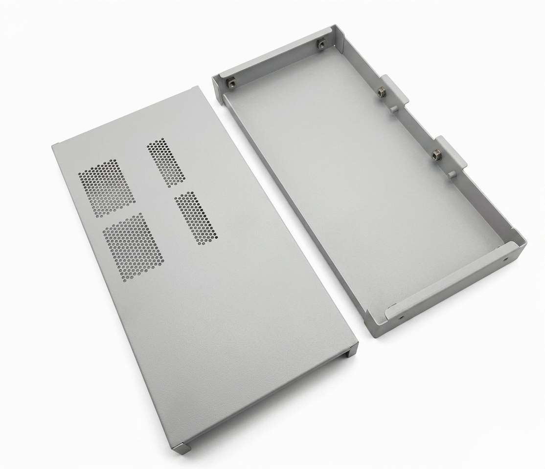
NCT 터렛펀칭 공정의 공차 형성 메커니즘
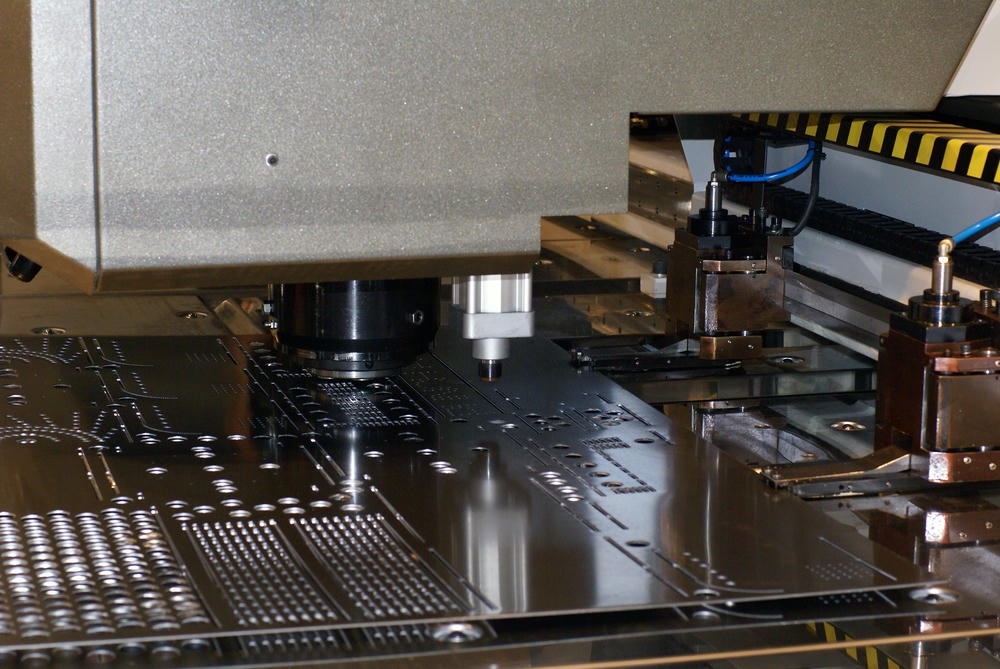
NCT 터렛펀칭은 상부 펀치가 하부 다이와의 간극을 이용하여 금속판을 전단(shearing)시키는 공정입니다. 이 과정에서 치수 정밀도에 영향을 미치는 주요 변수는 펀치-다이 클리어런스, 재료의 기계적 특성, 금형 마모 상태, 클램핑 조건, 그리고 가공 순서(nesting sequence)입니다.
클리어런스는 일반적으로 재료 두께의 5~10% 수준으로 설정하는 것이 표준이지만, 재질에 따라 편차가 큽니다. 냉간 압연 강판(SPCC)의 경우 두께의 8%가 최적값이며, 스테인리스강(SUS304)은 재료의 연성과 가공 경화 특성 때문에 10~15%까지 확대 적용합니다. 반면 얇은 알루미늄(AL5052, 1mm 이하)은 5~7% 수준으로 타이트하게 설정해야 전단면 품질이 확보됩니다. 클리어런스가 부적절하면 버(burr) 발생이 심해지고, 전단면의 롤오버(roll-over)·버니시드존(burnished zone)·파단면(fracture zone) 비율이 왜곡됩니다.
정상적인 전단면은 전체 두께의 약 1/3이 버니시드존, 2/3가 파단면으로 구성되는 것이 이상적입니다. 클리어런스가 과도하게 크면 파단면 비율이 증가하고 전단각도가 커지며 홀의 실효 직경이 작아지는 부정적 효과가 나타납니다. 반대로 클리어런스가 너무 작으면 이중 파단(secondary shearing)이 발생하여 표면에 결함이 남고 금형 수명이 급격히 단축됩니다. 일본 JIS B 0410 규격과 독일 DIN 6930 규격에서도 이 3분할 이론을 기반으로 전단면 품질 등급을 구분하고 있습니다.
펀치 금형 마모가 공차에 미치는 영향
동일한 금형이라도 가공 횟수가 누적되면 펀치의 에지 라운딩(edge rounding)이 진행되어 실제 클리어런스가 커지는 효과가 나타납니다. 일반적으로 고속 NCT 장비에서 50,000~100,000 타 수준에서 1차 재연마가 필요하며, 이를 방치할 경우 홀 직경 편차가 0.05mm 이상 벌어질 수 있습니다. 양산 현장에서 로트 초기에는 합격이던 부품이 로트 후반에 불합격으로 바뀌는 원인의 대부분이 이 금형 마모에서 비롯됩니다.
설계 단계에서는 이를 감안하여 기능 홀의 공차를 H7급으로 요구하기보다, NCT로는 H10~H11급으로 가공한 뒤 후공정에서 리머(reamer) 작업으로 정밀도를 확보하는 이원화 전략이 바람직합니다. 특히 베어링 압입부, 핀 고정 홀, 정렬용 가이드 홀과 같이 H7 이상의 정밀도를 요구하는 피처는 NCT 단일 공정으로 해결하려 하지 말아야 합니다. 이러한 이원화 전략은 글로벌 자동차 및 전자 업계의 판금 부품 가공 표준에서도 공통적으로 채택되고 있는 방식입니다.
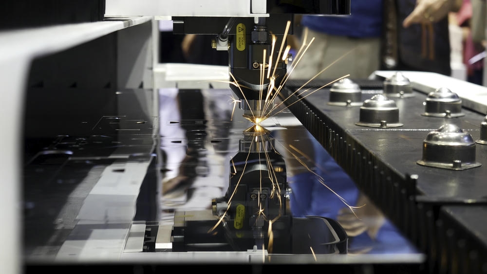
후처리 공정별 피막 형성 특성과 치수 변화 메커니즘
후처리는 크게 적층형(additive)과 침투형(conversion)으로 구분됩니다. 적층형은 도장이나 도금처럼 표면 위에 새로운 층이 쌓이는 방식이고, 침투형은 아노다이징처럼 기존 모재 표면을 화학적으로 변환시키는 방식입니다. 각 방식은 치수 변화의 양상이 근본적으로 다르므로 공차 보정 방식도 달라야 합니다.
전기 도금의 경우 아연 도금은 편측 5~12μm, 니켈 도금은 10~20μm, 경질 크롬 도금은 20~50μm의 피막을 형성합니다. 도금은 전류 밀도가 집중되는 에지 부위에서 두께가 두꺼워지는 에지 이펙트(edge effect) 가 발생하므로, 평면부 대비 에지부에서 1.5~2배까지 두께 편차가 날 수 있습니다. 이 특성 때문에 도금 후 홀 직경은 이론적 두께 감소량보다 더 크게 줄어드는 경향을 보입니다.
분체 도장(Powder Coating) 은 건조 후 막 두께가 60~120μm에 달하며, 모서리와 코너에서 더 두꺼워지는 특성이 있습니다. 액체 도장은 20~50μm 수준으로 비교적 얇지만, 흐름성 때문에 수평면과 수직면의 두께 편차가 발생합니다. 분체 도장의 경우 모서리 집중 현상이 특히 심하게 나타나는데, 흥미롭게도 날카로운 에지에서는 도료의 정전기적 반발 현상인 패러데이 케이지 이펙트(Faraday cage effect) 로 오히려 두께가 얇아지는 역설적 현상도 발생합니다. 따라서 분체 도장이 예정된 부품은 모서리에 최소 R0.5 이상의 필렛을 부여하는 것이 도장 품질 확보에 유리합니다.
아노다이징(Anodizing) 은 알루미늄 표면에 산화막(Al₂O₃)을 형성시키는 공정으로, 생성된 산화막의 약 50%가 모재 내부로 침투하고 50%가 외부로 성장합니다. 정확히는 Type II 일반 아노다이징의 경우 외측 성장 비율이 약 45~50%, Type III 하드 아노다이징은 40~50% 수준으로 조건에 따라 변동됩니다. 즉 50μm의 하드 아노다이징을 적용하면 실제 외경 증가는 약 20~25μm이지만, 내경은 같은 양만큼 감소합니다. 이는 정밀 구멍 설계에서 반드시 계산해야 할 핵심 변수이며, MIL-A-8625 및 ISO 7599 규격에서도 이 양방향 성장 특성을 명확히 규정하고 있습니다.
후처리 전 오프셋 적용과 선택적 마스킹 전략
후처리 후 기능 치수를 정확히 확보하려면 NCT 가공 단계에서 미리 오프셋을 적용해야 합니다. 외경 치수는 피막 두께 × 2만큼 작게, 내경(홀) 치수는 피막 두께 × 2만큼 크게 가공하는 것이 원칙입니다. 단, 아노다이징은 외측 성장분만 고려하면 되므로 오프셋 양이 절반으로 줄어듭니다.
그러나 모든 피처에 오프셋을 일괄 적용하는 것은 비효율적이며, 오히려 외관 품질과 비용에 악영향을 줄 수 있습니다. 실무에서는 기능면과 비기능면을 명확히 구분하여 공차 전략을 차등화합니다. 외관에만 영향을 주는 비기능 홀은 표준 공차로 처리하고, 조립 간섭이 발생하는 기능 홀만 선택적으로 오프셋을 적용하는 방식입니다.
정밀 압입 홀, 베어링 시트, 가이드 핀 홀처럼 공차를 타이트하게 유지해야 하는 피처는 후처리 전 마스킹(masking) 을 적용하여 코팅이 형성되지 않도록 하는 방식이 효과적입니다. 마스킹 방법으로는 실리콘 캡, 고온 내열 테이프, 전용 플러그 등이 사용되며, 마스킹 위치와 사양은 반드시 도면에 명시해야 업체와의 공정 분쟁을 예방할 수 있습니다. 도면에는 “ANODIZING MASK AREA” 또는 “PLATING EXCLUDE ZONE”과 같은 명확한 지시어와 함께 해당 영역을 별도 해치(hatch) 처리하여 표기하는 것이 국제 표준 관행입니다.
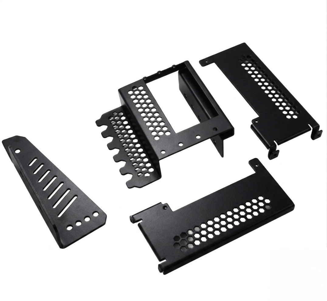
도금 후 나사 체결부의 치수 보정
나사 체결부는 후처리 치수 보정에서 가장 민감한 영역입니다. M4 탭 홀을 예로 들면, NCT 펀칭으로는 피치 홀(pilot hole)만 가공하고 탭 가공은 별도로 진행되는데, 피치 홀 직경이 3.3mm일 때 아연 도금(편측 8μm 기준)을 거치면 실효 직경이 약 3.28mm로 감소합니다. 이 정도는 탭 가공에 큰 영향이 없지만, 관통 홀에 나사가 자유롭게 통과해야 하는 경우에는 M4 볼트 기준 여유 홀 4.5mm가 도금 후 4.48mm로 축소되어 특정 제조 공차의 볼트와 간섭을 일으킬 수 있습니다.
따라서 후처리가 예정된 체결부는 여유 홀 직경을 0.1~0.2mm 크게 설계하는 것이 표준이며, 특히 분체 도장이 적용되는 부품은 0.3mm 이상의 여유를 주는 것이 안전합니다. 이러한 세부 지침을 도면에 일관되게 적용하려면 회사 내부의 도장 여유 기준표(coating clearance table) 를 마련하여 설계자 간 편차를 최소화하는 것이 바람직합니다. 일본 JIS 및 독일 VDMA 가이드라인에서는 이를 “코팅 얼라우언스(coating allowance)”로 정식 개념화하여 설계 단계에 반영할 것을 권장하고 있습니다.
NCT 후 절곡 공정의 소성 변형 역학
NCT로 가공된 평판이 절곡기에서 굽혀지는 순간, 재료 내부에서는 복잡한 응력 분포가 형성됩니다. 외측은 인장(tensile), 내측은 압축(compressive) 응력을 받으며, 두 응력이 균형을 이루는 지점이 중립축(neutral axis) 입니다. 이상적인 탄성 변형에서는 중립축이 정확히 두께 중앙에 위치하지만, 실제 소성 변형에서는 중립축이 내측 방향으로 이동합니다.
중립축의 이동 정도를 수치화한 것이 K-Factor 로, 내측 표면에서 중립축까지의 거리를 재료 두께로 나눈 값입니다. K-Factor는 재질, 두께, 절곡 반경, 다이 폭, 펀치 R값에 의해 결정되며, 다음과 같은 일반적 범위를 갖습니다. SPCC 연강은 0.35~0.44, SUS304 스테인리스강은 0.40~0.47, AL5052 알루미늄은 0.33~0.40 수준입니다. 동일한 재질이라도 절곡 반경이 두께의 1배 이하일 때는 K-Factor가 작아지고, 3배 이상일 때는 0.5에 가까워집니다. 이 관계는 DIN 6935 표준에서 수학적 모델로 정립되어 있으며, 현대의 주요 CAD 소프트웨어는 이 모델을 기반으로 전개도를 자동 산출하고 있습니다.
Bend Allowance와 Bend Deduction 계산의 정확성
전개도 산출의 정확성은 Bend Allowance(BA) 또는 Bend Deduction(BD)의 정확한 적용에 달려 있습니다. BA의 수학적 정의는 BA = (π/180) × 각도 × (R + K × T) 이며, 여기서 R은 내측 절곡 반경, T는 재료 두께, K는 K-Factor입니다. 90° 절곡의 경우 BA = 1.5708 × (R + K × T)로 간략화됩니다. 반대로 Bend Deduction은 BD = 2 × (R + T) × tan(각도/2) − BA로 산출되며, 두 플랜지 합산 치수에서 BD를 빼는 방식으로 평판 전개 길이를 구합니다.
문제는 대부분의 CAD 소프트웨어가 기본 K-Factor를 0.44로 설정하고 있다는 점입니다. 이 값은 일반 연강에는 대체로 맞지만, 스테인리스나 알루미늄, 고장력강에는 상당한 오차를 발생시킵니다. 두께 2mm SUS304의 90° 절곡에서 K-Factor를 0.44로 계산했을 때와 실제 값인 0.46으로 계산했을 때의 BA 차이는 약 0.06mm이며, 3회 절곡 시 0.18mm의 치수 오차로 누적됩니다. 정밀 부품에서는 이 정도 오차도 무시할 수 없으므로, 실제 사용하는 절곡기의 V-다이 폭과 펀치 R값을 기준으로 시편 테스트를 통해 K-Factor를 실측하는 것이 이상적입니다. 주요 절곡기 제조사들(Amada, Trumpf, LVD)은 자체 K-Factor 데이터베이스를 제공하고 있으나, 실제 현장 조건에 맞춰 재교정하는 것이 양산 안정성 확보의 핵심입니다.
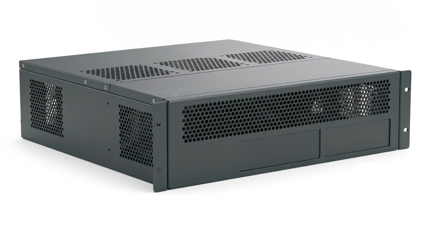
최소 절곡 거리 규칙과 홀 변형 방지
NCT로 펀칭된 홀이나 슬롯이 절곡선에 너무 가까우면, 절곡 시 발생하는 소성 변형 영역에 홀이 포함되어 타원형으로 일그러지거나 내부로 말려 들어가는 변형이 발생합니다. 심한 경우 홀 주변의 재료가 인장 한계를 초과하여 균열(cracking)이 발생하기도 합니다.
업계 표준 기준은 홀 가장자리에서 절곡선 내측 R까지의 거리가 재료 두께의 2배 + 절곡 반경(R) 이상을 유지하는 것입니다. 두께 1.5mm, 절곡 반경 1mm 기준으로는 최소 4mm 이상의 여유가 필요합니다. 이보다 가까운 거리에 홀이 필요하다면, 릴리프 노치(relief notch) 또는 릴리프 컷(relief cut) 을 미리 NCT 단계에서 가공하여 소성 변형 영역과 홀을 물리적으로 분리시키는 설계가 요구됩니다.
슬롯이나 대형 개구부는 상황이 더 까다롭습니다. 장축이 절곡선과 평행한 경우에는 일반 규칙을 따르면 되지만, 장축이 절곡선을 가로지르는 경우에는 슬롯 양끝에 응력 완화 컷(stress relief cut)을 추가하여 응력 집중점을 분산시켜야 합니다. 응력 완화 컷의 크기는 재료 두께의 1.5배 직경 원형 컷이 일반적이며, 위치는 절곡선 연장선상에 정확히 배치해야 효과가 극대화됩니다.
릴리프 노치의 형상과 크기 기준
릴리프 노치는 절곡선 양 끝단에 작은 슬롯이나 원형 컷을 추가하여 절곡 응력이 주변 피처로 전달되지 않도록 차단하는 역할을 합니다. 일반적으로 노치 폭은 재료 두께의 1.5배 이상, 깊이는 절곡선으로부터 재료 두께만큼 확장하는 것이 표준입니다. 원형 릴리프의 경우 직경을 재료 두께의 1.5~2배로 설정합니다.
릴리프 노치는 단순히 응력 분산 기능만 하는 것이 아니라, 절곡 후 인접 플랜지(flange) 간의 간섭을 방지하고 다음 공정인 용접이나 도장 시 수분이나 잔류물이 고이는 포켓을 제거하는 부가 효과도 있습니다. 특히 박스 형태의 함체 설계에서 코너 절곡부에는 릴리프 노치가 필수적이며, 이를 누락하면 코너 부분이 서로 겹치거나 벌어져 정확한 직각이 나오지 않습니다. 의료기기나 통신장비 함체처럼 코너 기밀성이 요구되는 제품에서는 V-노치 + 레이저 용접이나 U-노치 + 실리콘 개스킷 같은 후속 공정을 고려한 노치 형상이 별도로 설계됩니다.
스프링백 현상의 메커니즘과 과절곡 보정
스프링백은 외력이 제거된 후 탄성 변형 성분이 복원되면서 절곡 각도가 되돌아가는 현상입니다. 탄성-소성 이론에 따르면 스프링백의 크기는 재료의 항복 강도(yield strength)에 비례하고 탄성 계수(Young’s modulus)에 반비례합니다. 따라서 고장력강과 스테인리스강은 스프링백이 크고, 연강이나 알루미늄은 상대적으로 작습니다.
구체적인 수치로 90° 절곡 기준 SPCC는 약 1~2°, SUS304는 3~5°, 고장력강(SPFC590 이상)은 5~10°의 스프링백이 발생합니다. 이를 보정하기 위해서는 과절곡(over-bending) 을 적용하여 실제 굽힘 각도를 목표보다 작게 설정해야 합니다. 예를 들어 SUS304에서 90°를 얻으려면 85~87°로 절곡해야 합니다. 절곡 반경이 작아질수록 스프링백이 감소하는 경향이 있으며, 이 특성을 이용해 정밀 각도가 필요한 부품에서는 일부러 작은 R값을 선택하기도 합니다.
현대의 CNC 절곡기에는 스프링백 자동 보정 기능이 탑재되어 있으나, 이는 장비별 학습 데이터에 기반하므로 업체마다 결과가 달라질 수 있습니다. 양산 의뢰 시에는 반드시 시제품 단계에서 실측 검증을 거쳐 보정값을 확정한 후, 해당 조건을 양산 사양으로 고정하는 절차가 필요합니다. 또한 판재의 롤링 방향(grain direction)에 대한 절곡 방향도 스프링백에 영향을 미칩니다. 압연 방향과 평행한 절곡은 수직 절곡 대비 스프링백이 약 10~20% 크게 나타나므로, 도면에 재료 압연 방향을 지정하는 것이 정밀도에 유리합니다.

다중 절곡 시 누적 오차와 벤딩 시퀀스 최적화
3회 이상의 다중 절곡이 필요한 복잡 형상에서는 절곡 순서가 최종 치수에 결정적 영향을 미칩니다. 첫 번째 절곡은 평판 에지를 백게이지(back gauge) 기준으로 삼아 정확도가 높지만, 두 번째 이후부터는 이미 형성된 절곡 에지를 기준점으로 삼아야 하므로 누적 오차가 단계별로 증가합니다.
실무에서는 가장 중요한 기능 치수가 걸린 피처를 첫 번째 또는 두 번째 절곡에 배치하고, 공차가 완화된 피처를 마지막 절곡으로 배치하는 전략을 취합니다. 또한 대칭 형상의 경우 양측에서 교대로 절곡하여 누적 오차를 상쇄시키는 방법도 유효합니다.
박스 형상에서는 “내측 먼저, 외측 나중” 원칙을 따르는 것이 기본입니다. 안쪽 플랜지를 먼저 절곡한 뒤 바깥쪽 플랜지를 절곡해야 절곡기 툴과의 간섭을 피할 수 있습니다. 이러한 순서는 도면 작성 단계에서 미리 검토하여 절곡 가능성 자체를 확보해야 하며, 불가능한 순서로 설계된 도면은 현장에서 제작 자체가 거부될 수 있습니다. 최근에는 3D CAM 소프트웨어의 절곡 시뮬레이션 기능을 활용하여 설계 단계에서 절곡 충돌을 사전 검증하는 것이 보편화되고 있습니다.
버 방향 제어와 도면 표기 방법
NCT 펀칭 시 버는 펀치 진입 반대면(다이 측) 에 형성됩니다. 이 버의 방향은 절곡과 조립, 후처리 품질 전반에 영향을 미치므로 설계 단계에서 명확히 규정해야 합니다.
버는 절곡의 내측으로 향하게 배치하는 것이 유리합니다. 외측으로 버가 향하면 인장 응력과 결합하여 균열의 시작점이 될 수 있기 때문입니다. 또한 조립 시 사용자 손에 닿는 외관면은 버가 없는 면이 되어야 하며, 기능면도 마찬가지입니다. 도장 품질 측면에서도 외측 버는 코팅 밀착력을 저하시키고 초기 부식의 기점이 되므로, 외관 중요 부품에서는 반드시 통제되어야 합니다.
도면 표기는 “Burr Side: Down” 또는 “Burr Direction: Inside” 와 같이 명시하며, 필요한 경우 방향 화살표를 병기합니다. 버 높이가 제품 기능에 영향을 주는 경우에는 “Max Burr Height: 0.05mm”와 같이 수치 기준도 함께 명기합니다. ISO 13715 규격에서는 버와 에지 상태에 대한 표준 지시 방법을 규정하고 있으며, 이를 도면에 적용하면 국제적으로 통용되는 명확한 사양 전달이 가능합니다. 버 제거가 반드시 필요한 부품은 별도 디버링 공정인 텀블링, 브러시 디버링, 또는 롤러볼 디버링을 지정해야 하며, 각 공정은 부차적인 치수 감소(통상 편측 20~50μm)를 유발하므로 공차에 반영해야 합니다.
재질별 NCT 가공 특성과 공차 적용의 차이
SPCC 냉간 압연 강판은 NCT 가공성이 가장 우수한 재질로, 표준 클리어런스 8% 적용 시 안정적인 전단면을 얻을 수 있습니다. 도금이나 도장이 수반되는 경우가 많으므로 후처리 오프셋을 반드시 반영해야 합니다. SPHC 열간 압연재는 표면 스케일로 인해 펀칭 후 스케일 비산이 발생하며, 금형 수명이 짧아지므로 주기적인 금형 점검이 필요합니다.
SUS304·SUS316 스테인리스강은 가공 경화 특성이 강하여 클리어런스를 크게 설정해도 전단면 품질이 저하됩니다. 또한 항복 강도가 높아 절곡 시 스프링백이 크고, 펀치에 걸리는 하중이 SPCC 대비 1.5~2배에 달합니다. 따라서 두꺼운 스테인리스(2mm 이상) 가공은 NCT 장비의 톤수(tonnage) 용량을 반드시 확인해야 하며, 펀치 형상이 복잡할수록 분할 가공(nibbling) 전략이 유효합니다. 스테인리스 특유의 가공 경화로 인해 재펀칭 영역에서는 경도가 20~30% 상승하므로, 동일 위치 재가공은 피해야 합니다.
AL5052·AL6061 알루미늄은 연성이 우수하여 가공성이 좋지만, 얇은 판에서는 펀치에 재료가 부착되는 갈링(galling) 현상이 발생할 수 있습니다. 이를 방지하기 위해 펀치 표면에 TiN 또는 DLC 코팅을 적용하거나 가공유를 적절히 사용합니다. 아노다이징이 적용되는 경우 표면 결함이 그대로 드러나므로, 절삭면 품질 관리가 철강 대비 훨씬 까다롭습니다. 특히 Type III 하드 아노다이징은 모재의 미세 결함을 증폭시켜 보이므로, NCT 단계에서부터 결함 관리 기준을 엄격히 설정해야 합니다.
고장력강(SPFC590, SPFC780 이상) 은 자동차 부품과 구조재에서 주로 사용되며, NCT 가공 시 금형 파손 위험이 높습니다. 펀치는 분말 하이스강(PM-HSS)이나 초경(Tungsten Carbide) 재질을 사용해야 하며, 클리어런스는 재료 두께의 12~18%로 설정합니다. 이 재질은 스프링백이 10° 이상에 달하므로, 절곡 공정 설계 시 반드시 시험 벤딩을 통해 보정값을 확보해야 합니다.
재질별 NCT·절곡·후처리 통합 공차 및 설계 파라미터
| 재질 구분 | 적정 두께 (mm) | 펀치-다이 클리어런스 (%T) | 90° 절곡 K-Factor | 스프링백 보정 (°) | 최소 절곡 반경 (×T) | 최소 홀-절곡선 거리 | 일반 후처리 방식 | NCT 오프셋 보정 (편측, mm) |
|---|---|---|---|---|---|---|---|---|
| SPCC 냉간압연강 | 0.8 ~ 3.2 | 7 ~ 9% | 0.38 ~ 0.42 | 1 ~ 2° | 1.0T | 2T + R | 아연도금, 분체도장 | 도금 +0.05~0.10 / 도장 +0.15~0.30 |
| SPHC 열간압연강 | 1.6 ~ 6.0 | 9 ~ 11% | 0.40 ~ 0.44 | 1 ~ 3° | 1.5T | 2.5T + R | 분체도장, 용융아연도금 | 도장 +0.20~0.35 |
| SUS304 스테인리스 | 0.5 ~ 3.0 | 10 ~ 13% | 0.42 ~ 0.46 | 3 ~ 5° | 1.5T | 3T + R | 헤어라인, 전해연마 | 표면처리 +0.02~0.05 |
| SUS316 스테인리스 | 0.8 ~ 3.0 | 12 ~ 15% | 0.42 ~ 0.46 | 4 ~ 6° | 1.5T | 3T + R | 전해연마, 부동태화 | 표면처리 +0.02~0.05 |
| AL5052 알루미늄 | 0.5 ~ 3.0 | 6 ~ 8% | 0.33 ~ 0.38 | 1 ~ 2° | 0.8T | 1.5T + R | Type II 아노다이징 | 아노다이징 +0.01~0.03 |
| AL6061 알루미늄 | 0.8 ~ 4.0 | 7 ~ 10% | 0.35 ~ 0.40 | 2 ~ 3° | 1.0T | 2T + R | Type II/III 아노다이징 | Type II +0.02 / Type III +0.05 |
| SPFC590 고장력강 | 1.0 ~ 2.5 | 12 ~ 16% | 0.42 ~ 0.48 | 5 ~ 8° | 2.0T | 3T + R | 아연도금, 분체도장 | 도금 +0.10~0.15 |
| SPFC780 초고장력강 | 1.0 ~ 2.0 | 14 ~ 18% | 0.44 ~ 0.50 | 7 ~ 10° | 2.5T | 3.5T + R | 아연도금 | 도금 +0.10~0.15 |
| C1100 동판 | 0.5 ~ 2.0 | 7 ~ 9% | 0.36 ~ 0.40 | 0.5 ~ 1° | 0.8T | 1.5T + R | 니켈/크롬도금 | 도금 +0.10~0.20 |
| 황동 (C2680) | 0.5 ~ 2.0 | 6 ~ 8% | 0.38 ~ 0.42 | 1 ~ 2° | 1.0T | 1.5T + R | 니켈도금, 크롬도금 | 도금 +0.10~0.15 |
공차 스택업 분석의 실무 적용
여러 피처가 상호 관계를 갖는 부품에서는 통계적 공차 스택업 분석(statistical tolerance stack-up) 이 필요합니다. 단순 산술 합산(worst-case)으로 공차를 누적하면 실제 불량률보다 훨씬 크게 계산되어 과도한 가공 사양이 요구됩니다. 반면 RSS(Root Sum Square) 방식 은 각 공차의 제곱 합의 제곱근으로 계산하여 현실적인 확률 분포에 가까운 결과를 제공합니다.
두께 2mm 강판에 3개의 절곡 후 형성되는 벤드-투-벤드 치수의 경우, 각 절곡의 공차가 ±0.25mm라면 worst-case로는 ±0.75mm이지만, RSS로는 ±0.43mm가 나옵니다. 실제 관리 범위는 이 두 값 사이에서 결정되며, 기능 요구에 따라 선택됩니다. Six Sigma 품질 수준(Cpk ≥ 1.33)을 요구하는 양산에서는 RSS 방식이 표준적으로 채택되며, 안전 여유가 필수적인 항공·의료기기에서는 worst-case 방식이 적용됩니다.
중요한 것은 기능 치수(critical dimension)에 공차 예산을 집중하는 것입니다. 예를 들어 전체 부품이 ±0.5mm 예산을 갖는다면, 조립 홀 간 거리에는 ±0.2mm를 할당하고, 외곽 윤곽은 ±0.5mm로 완화시켜 전체 공정 비용을 최적화합니다. 이 공차 예산 분배는 GD&T(Geometric Dimensioning and Tolerancing) 기반의 체계적 접근을 통해 가장 효과적으로 수행됩니다. 단순 치수 공차가 아닌 위치도(position tolerance), 평행도(parallelism), 직각도(perpendicularity) 등의 기하 공차를 활용하면 기능 요구를 정확히 표현하면서도 제조 유연성을 확보할 수 있습니다.
펨너트·스탠드오프 압입부의 특수 공차 관리
압입 화스너(self-clinching fastener)는 판재의 구멍 직경에 매우 민감합니다. PEM사의 S-type 펨너트 기준, M4 사이즈 압입 홀은 4.22~4.27mm 범위의 매우 타이트한 공차를 요구합니다. NCT 펀칭으로 이 공차를 안정적으로 확보하려면 전용 정밀 금형과 정기적인 공차 검증이 필요합니다.
후처리와의 순서 관계도 중요합니다. 도장이 적용되는 부품에서 압입 공정을 도장 전에 수행하면 도막 균열과 방식 성능 저하가 발생할 수 있고, 도장 후에 수행하면 홀 직경 감소로 인한 압입력 부족으로 펨너트의 회전 저항이 사양을 만족하지 못할 수 있습니다. 최적 순서는 도장 전 압입을 완료하고, 도장 시 펨너트 나사부를 마스킹하는 방식이지만, 이는 공정 비용과 품질의 균형을 고려하여 결정해야 합니다.
아노다이징이 적용되는 알루미늄 부품의 경우는 더 복잡합니다. 압입 후 아노다이징을 하면 산화막이 압입면에 형성되어 전기적 접지가 불량해지고, 펨너트가 강판 재질이면 이종 금속 접촉 부식(galvanic corrosion)의 위험이 발생합니다. 따라서 알루미늄 부품은 아노다이징 후 펨너트를 압입하되, 홀 직경을 산화막 성장분만큼 미리 보정하는 것이 정석입니다. 접지가 기능적으로 중요한 통신장비나 전자 장비에서는 펨너트 접촉부 전체를 마스킹하는 별도 지시가 필요하며, 이 영역은 도면에 “Bare Metal Contact Zone”으로 명기합니다.
시제품 검증과 양산 이관의 공차 고정 절차
초기 설계 단계에서 아무리 정밀한 공차 분석을 수행해도, 실제 가공 결과와의 차이가 발생할 수 있습니다. 따라서 NCT → 절곡 → 후처리의 전체 공정을 거친 시제품을 제작하여 실측 검증하는 단계가 필수적입니다. 이 단계에서 확인해야 할 항목은 절곡 각도의 실제 스프링백 보정값, 다중 절곡 시 누적 편차의 방향성, 후처리 두께의 부위별 편차(특히 모서리부), 압입 홀의 실제 공차 분포, 조립 시 발생하는 간섭 부위의 상세 치수입니다.
시제품 데이터는 단순 합격/불합격 판정이 아니라, 공정 조건을 확정하는 기준 데이터(baseline)로 활용되어야 합니다. 검증 완료된 조건은 PPAP(Production Part Approval Process)나 FAI(First Article Inspection) 보고서 형태로 문서화되며, 이후 양산에서는 이 기준 대비 편차 관리가 이루어집니다.
양산 이관 단계에서는 시제품에서 검증된 가공 조건(금형 설정, 절곡기 프로그램, 후처리 라인 조건)을 표준 작업 지시서(SOP)로 문서화하고, 동일 조건이 유지되는지 정기 검증합니다. 특히 금형 마모 관리 주기, 장비 교정 주기, 재료 로트 변동 관리가 공차 안정성 유지의 3대 축입니다. SPC(Statistical Process Control) 기법을 도입하여 주요 공차 항목을 관리도(control chart)로 모니터링하면, 불량 발생 이전에 공정 이상을 조기 감지할 수 있습니다.
국제 규격과 설계 표준 체계의 활용
판금 공차 설계에서 국제 규격을 적극 활용하면 설계 효율성과 업체 간 의사소통이 크게 개선됩니다. ISO 2768-mK는 일반 공차 표준으로, 특별한 공차 지정이 없는 치수에 자동 적용되는 중급 공차(m) 및 기하 공차(K)를 정의합니다. 이를 도면 우측 상단에 명기하면 세부 치수마다 공차를 표기할 필요가 없어 도면이 간결해집니다.
ISO 13920은 용접 구조물의 일반 공차로, 판금 함체에 적합한 공차 등급을 정의합니다. DIN 6930과 JIS B 0410은 각각 독일과 일본의 전단 가공 공차 표준으로, NCT 펀칭의 정밀도 등급을 체계화하고 있습니다. 공정별로 적절한 규격을 선택하여 적용하는 것이 설계 품질의 기본입니다.
또한 GD&T를 활용한 설계는 기능 요구를 정확히 전달하는 가장 효과적인 방법입니다. 데이텀(datum) 기반의 기준점 설정, 위치도 공차를 통한 홀 패턴 관리, 복합 공차 블록(feature control frame)을 활용한 다중 요구 표현은 판금 부품의 복잡한 기능 요구를 간결하고 명확하게 표현합니다. 글로벌 제조 환경에서 한국 업체가 해외 발주를 받거나 해외 업체에 발주할 때, GD&T 기반 도면은 언어 장벽을 넘어 명확한 기술 소통을 가능하게 합니다.
통합 사고 방식적 NCT CNC 설계
NCT 터렛펀칭과 CNC 가공은 단순히 금속을 자르고 뚫는 기계 공정이 아닙니다. 각 공정은 후속 공정의 품질을 결정하는 선행 변수이며, 최종 제품의 기능성과 조립성은 초기 설계 단계에서 전체 공정을 얼마나 정밀하게 예측하고 반영했는지에 의해 좌우됩니다.
후처리 공정은 공차를 재정의하는 공정이며, 절곡 공정은 평면 치수를 입체 치수로 변환하는 공정입니다. 이 두 공정의 물리적·화학적 메커니즘을 정확히 이해하고 NCT 설계에 반영하는 것이, 불량 없는 양산을 달성하는 유일한 방법입니다. 설계자는 단일 공정의 최적화에 머물지 않고, 판금 제조 전체의 흐름을 통합적으로 설계하는 시스템 엔지니어링 관점을 갖추어야 합니다.
도면 하나에는 단순한 형상 정보만 담기는 것이 아니라, 재질 특성에 대한 이해, 가공 장비의 한계, 후처리 공정의 변수, 조립 단계의 요구사항이 모두 응축되어 있어야 합니다. 설계자가 현장의 가공 실무를 경험하고, 후처리 업체의 실제 공정을 방문하며, 조립 라인에서 발생하는 문제를 직접 확인하는 경험이 누적될수록 도면의 완성도는 높아집니다.
최종적으로 양질의 판금 부품은 도면에서 나오는 것이 아니라 설계-가공-후처리 부서 간의 긴밀한 기술 공유와 실측 데이터의 축적에서 나옵니다. 본 게시글에서 제시한 원칙과 수치들을 사내 설계 표준에 반영하여, 반복되는 불량과 클레임을 근본적으로 차단하는 기반으로 활용하기를 권합니다. 특히 중소 제조 현장에서는 이러한 기술 표준의 체계화가 곧 경쟁력 강화로 직결되며, 장기적으로는 고부가가치 정밀 부품 시장 진입의 발판이 됩니다. 판금 설계의 본질은 공차 그 자체가 아니라, 공차를 통제하는 체계적 설계 프로세스의 구축이 전체 품질을 좌우하는 기준이 됩니다.
A Comprehensive Guide to Tolerance Design in NCT Turret Punching: Integrating Post-Treatment and Bending Considerations
In sheet metal manufacturing, NCT turret punching and CNC machining are not merely tools for shaping metal — they are the starting point that determines the functionality and assemblability of the final product. Many engineers focus exclusively on dimensional accuracy at the machining stage, yet a significant proportion of field defects originate from failure to account for dimensional changes during post-treatment processes and plastic deformation during bending operations at the design stage. This article provides an in-depth, practice-oriented exploration of tolerance design methodology that holistically integrates post-treatment processes such as painting, plating, and anodizing with bending operations, all centered around NCT turret punching.
How Tolerances Accumulate Across Sheet Metal Processes
Sheet metal components typically undergo a three-stage process: blanking (NCT punching) → bending → post-treatment. Although each stage appears independent, dimensional deviations from each preceding stage propagate directly into subsequent ones, forming what is known as stack-up tolerance. Using a 1mm-thick SPCC steel sheet as an example, the NCT punching stage introduces hole position deviations on the order of ±0.1mm. The bending stage then adds ±0.15–0.25mm due to springback and K-Factor variations. Finally, when powder coating is applied at 60–100μm per side, the cumulative deviation from the original design dimension can exceed 0.3mm.
When this cumulative error is left unmanaged, components that pass single-stage inspections may cause severe interference during assembly, or threaded fasteners may become impossible to engage after post-treatment. Therefore, the fundamental principle is to set machining tolerances based on the final functional dimensions (post-process functional dimensions) by reverse-calculating from the entire process flow at the NCT design stage. This approach is endorsed by ISO 2768-mK general tolerance standards, ASME Y14.5 GD&T specifications, and the German VDI 3405 guidelines, all of which systematically codify tolerance frameworks for sheet metal processes.
The Tolerance Formation Mechanism in NCT Turret Punching
NCT turret punching is a process in which an upper punch shears a metal sheet using the clearance between it and a lower die. The primary variables affecting dimensional accuracy include punch-die clearance, the mechanical properties of the material, die wear condition, clamping configuration, and punching sequence (nesting sequence).
Clearance is typically set at 5–10% of material thickness as standard practice, though this varies significantly by material. For cold-rolled steel (SPCC), 8% of thickness is the optimal value. Stainless steel (SUS304), due to its ductility and work-hardening characteristics, requires an extended clearance of 10–15%. Conversely, thin aluminum sheet (AL5052, below 1mm) demands a tighter clearance of 5–7% to achieve acceptable shear-face quality. Improper clearance leads to excessive burr formation and distortion of the roll-over, burnished zone, and fracture zone proportions across the shear face.
A properly formed shear face ideally consists of approximately one-third burnished zone and two-thirds fracture zone across the total thickness. Excessively large clearance increases the fracture zone ratio, enlarges the shear angle, and effectively reduces the hole diameter. Conversely, excessively tight clearance causes secondary shearing, which leaves surface defects and drastically shortens die life. Both JIS B 0410 and DIN 6930 standards classify shear-face quality grades based on this tri-zone theory.
The Impact of Punch Die Wear on Tolerances
Even with identical tooling, accumulated punch strokes cause progressive edge rounding, which effectively increases the functional clearance. Generally, initial regrinding is required at approximately 50,000–100,000 strokes on high-speed NCT equipment, and failure to address this can cause hole diameter deviations exceeding 0.05mm. In production environments, the common scenario of parts passing inspection at the beginning of a lot but failing toward the end is most frequently attributable to this die wear phenomenon.
At the design stage, rather than demanding H7-grade tolerances from NCT alone, a more prudent strategy is to machine to H10–H11 grade via NCT and then achieve final precision through secondary operations such as reaming. Features requiring H7 or tighter tolerances — such as bearing press-fit holes, pin-fixing holes, and alignment guide holes — should never be expected to achieve their required precision through NCT as a single process. This bifurcated strategy is a standard practice adopted across global automotive and electronics sheet metal manufacturing.
Dimensional Change Mechanisms by Post-Treatment Type
Post-treatment processes are broadly classified as additive (where a new layer is deposited on the surface, as in painting and plating) and conversion (where the existing substrate surface is chemically transformed, as in anodizing). Each type produces fundamentally different patterns of dimensional change, requiring correspondingly different tolerance compensation approaches.
For electroplating, zinc plating produces 5–12μm per side, nickel plating 10–20μm, and hard chrome plating 20–50μm. Plating exhibits an edge effect where current density concentrations at edges result in coating thickness up to 1.5–2 times greater than on flat surfaces. This characteristic means that post-plating hole diameter reduction tends to exceed the theoretical thickness reduction.
Powder coating produces a dry film thickness of 60–120μm, with thicker accumulation at corners and edges. Liquid painting is comparatively thinner at 20–50μm but exhibits thickness variation between horizontal and vertical surfaces due to flow behavior. Powder coating is particularly susceptible to corner concentration, though paradoxically, the Faraday cage effect — electrostatic repulsion at sharp edges — can cause thinner coating at very sharp edges. Accordingly, components destined for powder coating benefit from a minimum fillet radius of R0.5 at all edges to ensure coating quality.
Anodizing forms an oxide layer (Al₂O₃) on aluminum surfaces, with approximately 50% of the oxide growing inward into the substrate and 50% growing outward. More precisely, Type II standard anodizing exhibits an outward growth ratio of approximately 45–50%, while Type III hard anodizing is in the 40–50% range depending on conditions. Thus, applying 50μm of hard anodizing results in an actual outer diameter increase of approximately 20–25μm, while the inner diameter decreases by the same amount. This is a critical variable that must be calculated for precision hole design, and both MIL-A-8625 and ISO 7599 standards explicitly define this bidirectional growth characteristic.
Pre-Treatment Offset Application and Selective Masking Strategy
To achieve accurate functional dimensions after post-treatment, offsets must be applied at the NCT machining stage. The principle is straightforward: outer dimensions are machined smaller by coating thickness × 2, and inner dimensions (holes) are machined larger by coating thickness × 2. For anodizing, however, only the outward growth portion needs to be considered, so the offset is halved.
However, applying offsets uniformly to every feature is both inefficient and potentially detrimental to appearance quality and cost. In practice, functional and non-functional surfaces are clearly differentiated, and tolerance strategies are tiered accordingly. Non-functional holes affecting only appearance are processed with standard tolerances, while only functional holes subject to assembly interference receive selective offset treatment.
For features requiring tight tolerance maintenance — such as precision press-fit holes, bearing seats, and guide pin holes — pre-treatment masking is applied to prevent coating formation. Masking methods include silicone caps, high-temperature resistant tape, and dedicated plugs, and masking locations and specifications must be documented on the drawing to prevent disputes with vendors. Drawings should include clear directives such as “ANODIZING MASK AREA” or “PLATING EXCLUDE ZONE,” accompanied by distinct hatching of the affected zones — a standard international practice.
Dimensional Compensation for Threaded Fastener Interfaces After Plating
Threaded fastener interfaces represent the most sensitive area in post-treatment dimensional compensation. Taking an M4 tapped hole as an example: NCT punching produces only the pilot hole, with tapping performed separately. When the pilot hole diameter is 3.3mm, zinc plating (at 8μm per side) reduces the effective diameter to approximately 3.28mm. This reduction has minimal impact on tapping, but for clearance holes where a bolt must pass freely, the M4 bolt standard clearance hole of 4.5mm shrinks to 4.48mm after plating, potentially causing interference with bolts at certain manufacturing tolerances.
Accordingly, clearance holes on parts destined for post-treatment should be designed 0.1–0.2mm oversized, with powder-coated components requiring 0.3mm or more of additional clearance. To apply these guidelines consistently across drawings, it is advisable to establish an internal coating clearance table to minimize designer-to-designer variation. JIS and German VDMA guidelines formalize this as a “coating allowance” concept and recommend its integration at the design stage.
The Plastic Deformation Mechanics of Post-NCT Bending
When an NCT-punched flat blank is bent in a press brake, a complex stress distribution forms within the material. The outer surface experiences tensile stress, while the inner surface undergoes compressive stress. The point where these stresses balance is the neutral axis. In ideal elastic deformation, the neutral axis lies precisely at the center of the thickness, but in actual plastic deformation, it shifts toward the inner surface.
The K-Factor quantifies this shift as the ratio of the distance from the inner surface to the neutral axis, divided by the material thickness. K-Factor is determined by material type, thickness, bend radius, die width, and punch radius, with the following general ranges: SPCC mild steel at 0.35–0.44, SUS304 stainless steel at 0.40–0.47, and AL5052 aluminum at 0.33–0.40. For the same material, K-Factor decreases when the bend radius is less than 1× thickness and approaches 0.5 when it exceeds 3× thickness. This relationship is mathematically modeled in the DIN 6935 standard, and major contemporary CAD software packages calculate flat patterns based on this model.
Accuracy of Bend Allowance and Bend Deduction Calculations
The accuracy of flat-pattern development depends on the correct application of Bend Allowance (BA) or Bend Deduction (BD). The mathematical definition of BA is BA = (π/180) × angle × (R + K × T), where R is the inside bend radius, T is the material thickness, and K is the K-Factor. For a 90° bend, this simplifies to BA = 1.5708 × (R + K × T). Bend Deduction is calculated as BD = 2 × (R + T) × tan(angle/2) − BA, and the flat-pattern length is derived by subtracting BD from the sum of the two flange dimensions.
The problem is that most CAD software defaults to a K-Factor of 0.44. While this is generally acceptable for mild steel, it introduces significant errors for stainless steel, aluminum, and high-strength steel. For a 90° bend in 2mm SUS304, the BA difference between K-Factor 0.44 and the actual value of 0.46 is approximately 0.06mm, which accumulates to 0.18mm over three bends. For precision components, even this level of error cannot be ignored, making it ideal to determine K-Factor empirically through test specimens based on the actual V-die width and punch radius of the specific press brake being used. Major press brake manufacturers (Amada, Trumpf, LVD) provide proprietary K-Factor databases, but recalibration to actual shop-floor conditions remains the key to achieving production stability.
Minimum Bend Distance Rules and Hole Deformation Prevention
When NCT-punched holes or slots are positioned too close to the bend line, the plastic deformation zone generated during bending encompasses the hole, causing it to distort into an oval shape or fold inward. In severe cases, the material surrounding the hole may exceed its tensile limit and crack.
The industry standard criterion requires that the distance from the hole edge to the inside bend radius be at least 2× material thickness + bend radius (R). For 1.5mm thickness with a 1mm bend radius, this means a minimum clearance of 4mm. If a hole must be placed closer than this threshold, a relief notch or relief cut should be machined at the NCT stage to physically isolate the hole from the plastic deformation zone.
Slots and large apertures present additional challenges. When the long axis is parallel to the bend line, standard rules apply. However, when the long axis crosses the bend line, stress relief cuts must be added at both ends of the slot to distribute stress concentration points. The standard size for stress relief cuts is a circular cut with a diameter of 1.5× material thickness, positioned precisely on the extension of the bend line for maximum effectiveness.
Relief Notch Geometry and Sizing Standards
Relief notches are small slots or circular cuts added at both ends of the bend line to prevent bending stress from propagating to adjacent features. As a general rule, notch width should be at least 1.5× material thickness, and depth should extend from the bend line by at least the material thickness. For circular reliefs, the diameter is set at 1.5–2× material thickness.
Relief notches serve not only to distribute stress but also to prevent interference between adjacent flanges after bending and to eliminate pockets where moisture or residue could accumulate during subsequent welding or painting processes. In box-type enclosure designs, corner-bend relief notches are mandatory — omitting them results in corners that overlap or gap, preventing accurate right-angle formation. For products requiring corner hermeticity, such as medical equipment or telecommunications enclosures, notch geometry is specifically designed for subsequent processes, such as V-notch + laser welding or U-notch + silicone gasket configurations.
Springback Mechanics and Over-Bend Compensation
Springback is the phenomenon in which the elastic deformation component recovers after the external force is removed, causing the bend angle to partially revert. According to elastic-plastic theory, the magnitude of springback is proportional to the yield strength and inversely proportional to the elastic modulus (Young’s modulus) of the material. Consequently, high-strength steel and stainless steel exhibit large springback, while mild steel and aluminum exhibit comparatively less.
In specific terms, at a 90° bend, SPCC produces approximately 1–2° of springback, SUS304 produces 3–5°, and high-strength steel (SPFC590 and above) produces 5–10°. To compensate, over-bending is applied, setting the actual bend angle tighter than the target. For example, achieving 90° in SUS304 requires bending to 85–87°. Springback tends to decrease with smaller bend radii, and this characteristic is sometimes deliberately exploited by selecting smaller R values for parts requiring precise angles.
Modern CNC press brakes feature automatic springback compensation, but since this relies on machine-specific learned data, results can vary between vendors. When commissioning production, it is essential to verify compensation values through prototype measurement and then lock those conditions as production specifications. Additionally, the rolling direction (grain direction) of the sheet relative to the bend direction affects springback. Bending parallel to the rolling direction produces approximately 10–20% greater springback compared to perpendicular bending, so specifying material rolling direction on drawings benefits dimensional precision.
Cumulative Error in Multi-Bend Operations and Bending Sequence Optimization
For complex geometries requiring three or more bends, bending sequence has a decisive impact on final dimensions. The first bend references the flat-sheet edge against the back gauge and achieves high accuracy, but subsequent bends must reference already-formed bend edges, causing cumulative error to increase with each step.
In practice, features carrying the most critical functional dimensions are positioned at the first or second bend, while features with relaxed tolerances are assigned to the final bends. For symmetrical geometries, alternating bends from both sides can effectively cancel cumulative errors.
For box-shaped parts, the “inside first, outside last” principle is standard. Inner flanges are bent first, followed by outer flanges, to avoid interference with press brake tooling. This sequence must be verified at the drawing stage to ensure bendability, as designs with impossible bending sequences may be outright rejected on the shop floor. Contemporary 3D CAM software with bending simulation capabilities has made it commonplace to verify bend collision at the design stage.
Burr Direction Control and Drawing Notation
In NCT punching, burrs form on the side opposite to punch entry (the die side). Burr direction affects bending, assembly, and post-treatment quality across the board, so it must be clearly specified at the design stage.
Burrs should be oriented toward the inside of the bend. When burrs face outward, they combine with tensile stress and can serve as crack initiation points. Additionally, the exterior surface that contacts the user’s hands during assembly should be the burr-free side. From a coating quality perspective, external burrs degrade adhesion and become initiation points for early corrosion, making control mandatory on appearance-critical components.
Drawing notation should clearly state “Burr Side: Down” or “Burr Direction: Inside”, with directional arrows as needed. When burr height affects product function, quantitative criteria such as “Max Burr Height: 0.05mm” should also be specified. ISO 13715 defines standard notation methods for burr and edge conditions, and applying this standard enables internationally recognized specification communication. Components requiring burr removal must specify a dedicated deburring process — tumbling, brush deburring, or roller-ball deburring — each of which introduces secondary dimensional reduction (typically 20–50μm per side) that must be factored into tolerances.
Material-Specific NCT Machining Characteristics and Tolerance Application
SPCC cold-rolled steel offers the best NCT machinability, achieving stable shear faces with standard 8% clearance. Since plating or painting typically follows, post-treatment offsets must be reflected. SPHC hot-rolled material produces scale scatter after punching due to surface scale, and die life is shorter, necessitating regular die inspection.
SUS304 and SUS316 stainless steel have strong work-hardening tendencies that degrade shear-face quality even with enlarged clearance. Higher yield strength also means greater springback during bending, and punch loads are 1.5–2× those of SPCC. Consequently, thick stainless steel (2mm and above) requires verification of NCT equipment tonnage capacity, and nibbling strategies become effective for complex punch geometries. Due to the characteristic work-hardening of stainless steel, hardness increases by 20–30% in re-punched zones, so repeated machining at the same location should be avoided.
AL5052 and AL6061 aluminum offer excellent machinability due to their ductility, but thin sheets are susceptible to galling where material adheres to the punch. This is mitigated by applying TiN or DLC coatings to the punch surface or by using appropriate cutting fluids. When anodizing is applied, surface defects are directly revealed, making surface quality management considerably more demanding than for steel. Type III hard anodizing in particular amplifies microscopic substrate defects, requiring stringent defect management standards from the NCT stage onward.
High-strength steel (SPFC590, SPFC780 and above) is primarily used for automotive components and structural parts, and carries a high risk of die breakage during NCT processing. Punches must be fabricated from powdered metallurgy high-speed steel (PM-HSS) or tungsten carbide, with clearance set at 12–18% of material thickness. Springback exceeds 10° for these materials, making trial bending for compensation value determination mandatory in the bending process design.
Integrated Tolerance and Design Parameter Reference Table by Material
The following table consolidates the key parameters that must be applied by material when designing for NCT turret punching. Actual application should be adjusted to account for equipment specifications and lot-to-lot variation.
| Material | Applicable Thickness (mm) | Punch-Die Clearance (%T) | 90° Bend K-Factor | Springback Compensation (°) | Min. Bend Radius (×T) | Min. Hole-to-Bend Distance | Common Post-Treatment | NCT Offset Compensation (per side, mm) |
|---|---|---|---|---|---|---|---|---|
| SPCC Cold-Rolled Steel | 0.8 – 3.2 | 7 – 9% | 0.38 – 0.42 | 1 – 2° | 1.0T | 2T + R | Zinc plating, powder coating | Plating +0.05–0.10 / Coating +0.15–0.30 |
| SPHC Hot-Rolled Steel | 1.6 – 6.0 | 9 – 11% | 0.40 – 0.44 | 1 – 3° | 1.5T | 2.5T + R | Powder coating, hot-dip galvanizing | Coating +0.20–0.35 |
| SUS304 Stainless | 0.5 – 3.0 | 10 – 13% | 0.42 – 0.46 | 3 – 5° | 1.5T | 3T + R | Hairline finish, electropolishing | Surface treatment +0.02–0.05 |
| SUS316 Stainless | 0.8 – 3.0 | 12 – 15% | 0.42 – 0.46 | 4 – 6° | 1.5T | 3T + R | Electropolishing, passivation | Surface treatment +0.02–0.05 |
| AL5052 Aluminum | 0.5 – 3.0 | 6 – 8% | 0.33 – 0.38 | 1 – 2° | 0.8T | 1.5T + R | Type II anodizing | Anodizing +0.01–0.03 |
| AL6061 Aluminum | 0.8 – 4.0 | 7 – 10% | 0.35 – 0.40 | 2 – 3° | 1.0T | 2T + R | Type II/III anodizing | Type II +0.02 / Type III +0.05 |
| SPFC590 High-Strength Steel | 1.0 – 2.5 | 12 – 16% | 0.42 – 0.48 | 5 – 8° | 2.0T | 3T + R | Zinc plating, powder coating | Plating +0.10–0.15 |
| SPFC780 Ultra-High-Strength Steel | 1.0 – 2.0 | 14 – 18% | 0.44 – 0.50 | 7 – 10° | 2.5T | 3.5T + R | Zinc plating | Plating +0.10–0.15 |
| C1100 Copper | 0.5 – 2.0 | 7 – 9% | 0.36 – 0.40 | 0.5 – 1° | 0.8T | 1.5T + R | Nickel/chrome plating | Plating +0.10–0.20 |
| C2680 Brass | 0.5 – 2.0 | 6 – 8% | 0.38 – 0.42 | 1 – 2° | 1.0T | 1.5T + R | Nickel plating, chrome plating | Plating +0.10–0.15 |
Practical Application of Tolerance Stack-Up Analysis
For components where multiple features are dimensionally interrelated, statistical tolerance stack-up analysis is required. Simple arithmetic (worst-case) accumulation of tolerances calculates a much larger deviation than the actual defect rate, resulting in unnecessarily stringent machining specifications. The RSS (Root Sum Square) method calculates the square root of the sum of squared individual tolerances, providing results closer to realistic probability distributions.
For a bend-to-bend dimension formed after three bends on 2mm steel sheet, if each bend carries a tolerance of ±0.25mm, the worst-case result is ±0.75mm, while RSS yields ±0.43mm. The actual control range falls between these two values and is selected based on functional requirements. Six Sigma quality levels (Cpk ≥ 1.33) in production standardize on the RSS method, while safety-critical aerospace and medical applications apply the worst-case method.
The critical point is to concentrate the tolerance budget on critical dimensions. For example, if the overall component has a ±0.5mm budget, assembly hole spacing might be allocated ±0.2mm while the outer contour is relaxed to ±0.5mm, optimizing overall process cost. This tolerance budget allocation is most effectively executed through a GD&T (Geometric Dimensioning and Tolerancing) based systematic approach. Using geometric tolerances such as position tolerance, parallelism, and perpendicularity rather than simple dimensional tolerances enables precise expression of functional requirements while maintaining manufacturing flexibility.
Special Tolerance Management for Self-Clinching Fastener Interfaces
Self-clinching fasteners are extremely sensitive to sheet hole diameter. For PEM S-type clinch nuts, the M4 installation hole requires a very tight tolerance range of 4.22–4.27mm. Achieving this tolerance consistently via NCT punching demands dedicated precision tooling and regular tolerance verification.
The sequence relationship with post-treatment is equally critical. When painting is applied and clinching is performed before painting, coating cracking and corrosion protection degradation may occur. When clinching is performed after painting, the reduced hole diameter may result in insufficient clinch force, causing the nut’s torque-out resistance to fall below specification. The optimal sequence is to complete clinching before painting and mask the nut threads during painting, though this must be balanced against process cost and quality considerations.
Aluminum components with anodizing present additional complexity. Post-clinch anodizing forms an oxide layer on the clinch interface, degrading electrical grounding. If the clinch nut is steel, a galvanic corrosion risk arises from dissimilar metal contact. Therefore, the standard approach for aluminum parts is to clinch after anodizing while pre-compensating the hole diameter for oxide growth. For telecommunications and electronics enclosures where grounding is functionally critical, the entire clinch nut contact zone requires masking, designated on drawings as a “Bare Metal Contact Zone.”
Prototype Verification and Production Transfer Procedures
No matter how precise the tolerance analysis at the design stage, discrepancies with actual machining results are possible. Accordingly, fabricating prototypes that undergo the complete NCT → bending → post-treatment process flow for physical verification is essential. Key verification items include actual springback compensation values for bend angles, directional tendencies of cumulative deviation in multi-bend operations, zone-specific coating thickness variation (especially at edges), actual tolerance distribution of press-fit holes, and detailed dimensions at assembly interference points.
Prototype data should serve not merely as pass/fail judgments but as baseline data for locking in process conditions. Verified conditions are documented in PPAP (Production Part Approval Process) or FAI (First Article Inspection) reports, and subsequent production manages deviations against this baseline.
At the production transfer stage, machining conditions verified during prototyping (die settings, press brake programs, post-treatment line parameters) are documented in Standard Operating Procedures (SOPs), with periodic verification that identical conditions are maintained. In particular, die wear management cycles, equipment calibration intervals, and material lot variation management constitute the three pillars of tolerance stability maintenance. Implementing SPC (Statistical Process Control) with control charts for key tolerance items enables early detection of process anomalies before defects occur.
Leveraging International Standards and Design Specification Frameworks
Active use of international standards in sheet metal tolerance design dramatically improves both design efficiency and vendor communication. ISO 2768-mK is the general tolerance standard that defines medium-grade (m) and geometric tolerance (K) levels automatically applied to dimensions without specific tolerance callouts. Noting this in the upper right corner of the drawing eliminates the need for individual tolerance annotations on every dimension, simplifying the drawing.
ISO 13920 defines general tolerances for welded structures, with tolerance classes suited to sheet metal enclosures. DIN 6930 and JIS B 0410 are German and Japanese shearing tolerance standards, respectively, that systematically classify NCT punching precision grades. Selecting and applying the appropriate standard for each process is fundamental to design quality.
GD&T-based design is the most effective method for accurately conveying functional requirements. Datum-based reference point establishment, position tolerance for hole pattern management, and composite tolerance blocks (feature control frames) for expressing multiple requirements provide concise and unambiguous representation of complex functional demands for sheet metal components. In the global manufacturing environment, GD&T-based drawings enable clear technical communication across language barriers when Korean firms receive orders from overseas or place orders with international vendors.
The Integrated Mindset Required of Design Engineers
NCT turret punching and CNC machining are not simply mechanical processes for cutting and perforating metal. Each process is a preceding variable that determines the quality of subsequent operations, and the functionality and assemblability of the final product are governed by how precisely the designer predicted and incorporated the entire process flow at the initial design stage.
Post-treatment processes redefine tolerances, and bending processes transform planar dimensions into three-dimensional ones. Accurately understanding the physical and chemical mechanisms of these two process categories and reflecting them in the NCT design is the only path to defect-free production. The designer must transcend single-process optimization and adopt a systems engineering perspective that holistically integrates the entire sheet metal manufacturing flow.
A drawing contains far more than geometric information alone — it must condense an understanding of material properties, the limitations of processing equipment, post-treatment process variables, and assembly-stage requirements. As designers accumulate hands-on experience with shop-floor machining practices, visit post-treatment vendors’ actual processes, and personally observe problems arising on assembly lines, the completeness of their drawings will progressively improve.
Ultimately, high-quality sheet metal components do not originate from drawings alone but from close technical collaboration between design, machining, and post-treatment departments and the systematic accumulation of measured data. Incorporating the principles and figures presented in this article into internal design standards will serve as a foundation for fundamentally eliminating recurring defects and claims. Particularly for small and medium-sized manufacturing operations, systematizing these technical standards directly translates to competitive advantage and, in the long term, provides a springboard for entering the high-value precision component market. The essence of sheet metal design lies not in tolerances themselves but in building a systematic design process that controls them — a point that bears repeated emphasis.
추가 정보
NCT 터렛펀칭 가공은 판금 제조의 핵심 공정으로, 후처리(도장·도금·아노다이징)와 절곡 공정에서 발생하는 치수 변화를 사전에 반영한 공차 설계가 최종 제품의 품질을 좌우합니다. 본 페이지에서는 NCT 가공과 CNC 가공을 중심으로, 실무 설계자가 반드시 알아야 할 공차 설정 기준과 공정 간 누적 오차 관리 방법을 기술 문서 수준으로 정리하였습니다.
핵심 체크리스트 — NCT 터렛펀칭 공차 설계 시 점검 항목
- 펀치-다이 클리어런스를 재질·두께별로 차등 적용했는지 확인 (SPCC 8%, SUS304 10~15%, AL5052 5~7%)
- 후처리 피막 두께에 따른 홀 오프셋 보정값을 도면에 반영했는지 확인
- 기능 홀과 비기능 홀을 구분하여 공차를 차등 설정했는지 점검
- 절곡 K-Factor를 실제 장비의 V-다이 폭과 펀치 R값 기준으로 교정했는지 확인
- 홀-절곡선 간 최소 거리 규칙(2T+R 이상)을 준수했는지 점검
- 버(Burr) 방향을 절곡 내측으로 지정하고 도면에 명시했는지 확인
- 다중 절곡 시 벤딩 시퀀스와 누적 오차를 사전 시뮬레이션했는지 점검
- 펨너트·스탠드오프 압입부의 후처리 순서와 마스킹 여부를 결정했는지 확인
자주 묻는 질문 (FAQ)
NCT 터렛펀칭과 레이저 커팅의 공차 차이는 어느 정도인가요?
분체 도장 후 홀 직경은 얼마나 줄어드나요?
아노다이징 시 치수 변화가 도금과 다른 이유는 무엇인가요?
NCT 가공 후 절곡 시 홀이 찌그러지는 원인은 무엇인가요?
K-Factor란 무엇이고, 왜 전개도 정확성에 중요한가요?
스테인리스강(SUS304) 절곡 시 스프링백은 얼마나 되나요?
NCT 금형은 몇 타(stroke)마다 재연마가 필요한가요?
펨너트(PEM nut) 압입 홀의 공차 기준은 어떻게 설정하나요?
ISO 2768-mK는 판금 도면에서 어떤 역할을 하나요?
NCT 가공 도면에서 버(Burr) 방향은 어떻게 표기하나요?
NCT 가공과 CNC 정밀가공의 공정 선택 기준
NCT 터렛펀칭과 CNC 정밀가공은 목적과 대상에 따라 선택이 달라집니다. NCT는 0.6~6mm 두께의 판재에서 반복적인 홀·슬롯·성형 가공에 특화되어 있으며, 대량 생산 환경에서 높은 생산성을 확보할 수 있습니다. 반면 CNC 밀링이나 선반은 솔리드 소재의 3차원 절삭에 적합하며, H7 이하의 정밀 공차가 요구되는 기능 부위에서 강점을 보입니다. 양산 판금 부품에서는 NCT로 기본 형상을 가공한 뒤, CNC 정밀가공으로 압입부나 베어링 시트 등 고정밀 피처만 후가공하는 이원화 전략이 비용과 품질 양면에서 유리합니다.
정밀 프레스 가공과 NCT 터렛펀칭의 관계
NCT 터렛펀칭은 범용 금형을 조합하여 다양한 형상을 가공하는 유연성이 장점입니다. 반면 전용 금형을 사용하는 정밀 프레스 가공은 1회 타발로 복잡 형상을 동시에 구현하여 대량 생산에서 월등한 속도와 일관성을 갖습니다. 양산 수량이 수천 개 이상인 경우에는 프로그레시브 금형 기반의 프레스 가공이 경제적이며, 수백 개 수준의 중소량에서는 NCT가 금형 투자 없이 유연하게 대응할 수 있습니다. 설계 단계에서 예상 생산 수량과 형상 복잡도를 분석하여 최적의 공법을 선택하는 것이 중요합니다.
후처리 공정이 전기접점 부품에 미치는 영향
NCT로 가공된 판금 부품이 전기적 기능을 수행하는 경우, 후처리 공정의 선택은 단순한 외관 문제를 넘어 전기적 성능과 직결됩니다. 도금 두께와 종류에 따라 접촉 저항이 달라지며, 아노다이징은 절연층을 형성하므로 전기접점 부위에는 반드시 마스킹이 필요합니다. 도금 후 접촉면의 표면 거칠기와 경도 변화도 접점 수명에 영향을 주므로, 공차 설계 시 전기적 요구사항을 반드시 함께 검토해야 합니다.
구조 연결 부품과 판금 공차의 상관관계
판금으로 제작된 브래킷, 행거, 마운팅 플레이트 등 구조 연결용 부품은 체결 홀의 위치 정밀도가 조립 품질을 좌우합니다. NCT 펀칭 후 절곡을 거치는 부품에서는 다중 절곡에 의한 누적 오차가 체결부 간섭의 주요 원인이 됩니다. 이러한 구조 부품의 설계에서는 공차 스택업 분석을 통해 기능 홀의 위치 공차를 ±0.2mm 이내로 관리하고, 비기능 부위는 완화시켜 전체 공정 비용을 최적화하는 접근이 필요합니다.
판금 가공과 관련한 더 다양한 기술 정보와 설계 참고 자료는 아이디메탈 인사이트에서 확인하실 수 있습니다. 브레이징 및 금속접합소재나 케이블 와이어 하네스 등 판금 후속 공정과 연관된 주제도 함께 참고하시면 전체 공정 흐름을 이해하는 데 도움이 됩니다.
관련 페이지 바로가기