
샤프트 스냅링 홈 설계:
어깨면·축방향 고정과 가공·검사
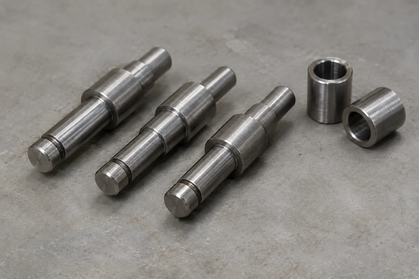
샤프트 스냅링 홈 설계는 링이 들어갈 홈을 만드는 것에서 끝나지 않습니다. 어깨면과 부시·와셔, 링과 홈 측벽이 축방향 하중을 어떻게 전달하는지 정하고, 조립 유격과 회전 조건, 가공 후 실제 치수를 함께 맞춰야 합니다. 홈이 작아 보여도 잘못된 모서리 형상이나 부족한 끝단 여유는 조립체 전체의 유지 기능을 바꿀 수 있습니다.
이 글은 축 바깥에 장착하는 DIN 471 계열의 축용 멈춤링을 중심으로 구조·치수·제조·검사를 연결합니다. 사진형 일러스트와 직접 돌려 보는 3D는 조립, 홈·어깨면 단면, 축방향 유격을 설명하는 개념 예시입니다. 실제 납품품·고객 도면·검증된 응력 해석이나 공통 허용치를 제시하는 자료는 아닙니다.
하중이 지나가는 면
어깨면·부시·링·홈 측벽의 역할과 링 용량·홈 용량의 차이를 설명합니다.
치수와 조립 유격
홈 지름·폭·끝단 여유, 필렛·모따기와 공차 누적을 연결합니다.
가공에서 검사까지
열처리·버·표면처리·장착 조건을 도면과 조립체 검증으로 정리합니다.
01고정 구조와 링의 선택
어깨면과 스냅링이 만드는 축방향 고정
샤프트 스냅링 홈 설계의 출발점은 부품이 어느 방향으로 움직이지 않아야 하는지 정하는 일입니다. 이 글의 기본 조립체는 단차가 있는 샤프트, 그 위에 끼운 부시, 부시의 바깥쪽을 막는 축용 멈춤링으로 구성됩니다. 샤프트 어깨면과 링이 서로 반대쪽의 축방향 정지면을 만들고, 원통형 끼워맞춤 면은 별도로 부시의 위치를 안내합니다.
부시가 축 끝쪽으로 밀리면 부시 또는 중간 와셔의 끝면이 링을 누릅니다. 링은 하중을 받는 홈 측벽에 반력을 전달하고, 그 측벽 뒤에 남은 축 재료가 힘을 지지합니다. 반대로 부시가 어깨면 쪽으로 밀릴 때에는 부시 끝면에서 어깨면으로 힘이 전달됩니다. 두 하중 방향은 같은 부품을 사용하더라도 서로 다른 접촉 경로를 가집니다.
링의 바깥으로 드러난 부분은 부시가 넘어가지 못하게 하는 걸림부이고, 홈 안에 들어간 부분은 축에 힘을 전달하는 맞물림부입니다. 화면에 링이 보인다는 사실과 충분히 맞물렸다는 사실은 다릅니다. 홈의 일부에만 걸려 있거나 큰 모따기 위에 걸쳐 있는 링은 겉으로 조립된 것처럼 보여도 의도한 접촉 상태가 아닐 수 있습니다.
축방향 유지와 회전 전달을 구분하기
평평한 멈춤링을 장착했다고 해서 부시가 축과 함께 회전하도록 잠기지는 않습니다. 토크를 전달해야 한다면 키·스플라인·압입 등 그 기능을 담당하는 구조를 따로 검토합니다. 같은 이유로 축에 있는 링의 탄성 조임을 부시 전체의 축방향 예압으로 해석해서도 안 됩니다. 반경 방향의 장착 탄성과 축방향 압착력은 다른 항목입니다.
| 구성 요소 | 주된 역할 | 함께 확인할 면 |
|---|---|---|
| 샤프트 어깨면 | 한쪽 방향의 축방향 정지 | 부시 끝면·필렛 회피부 |
| 부시·와셔 | 하중 전달과 조립 길이 형성 | 링과 접촉하는 유효 끝면 |
| 축용 멈춤링 | 반대 방향의 이탈 방지 | 부시 접촉면·홈 측벽 접촉면 |
| 홈과 끝단 재료 | 링 반력 지지 | 하중 측벽·홈 바닥·끝단 여유 |
베어링을 유지하는 경우에는 부시 예시를 그대로 복사하지 않습니다. 내륜을 축에 고정하는 링과 외륜을 하우징에 고정하는 링은 다른 위치에 작용합니다. 어떤 베어링 링을 지지하는지, 회전부와 정지부가 닿지 않는지, 필요한 축방향 이동을 막지 않는지까지 조립도에서 확인해야 합니다.
실제 접촉 순서와 모델의 읽기
설계 검토에서는 먼저 단면 위에 실제 접촉면과 하중 화살표를 표시하는 편이 유용합니다. 부품 사이에 틈이 있으면 처음부터 모든 면이 동시에 힘을 받지 않습니다. 유격이 닫힌 뒤 어느 면이 먼저 닿는지를 따라가면, 와셔를 추가하거나 홈 위치를 변경할 때 무엇이 달라지는지 설명할 수 있습니다.
본문의 3D는 이 접촉 관계를 보기 위한 개념 모델입니다. 조립 단계에서는 링의 벌어짐과 복귀를, 단면에서는 홈 안쪽 맞물림과 어깨면의 여유를, 유격 모델에서는 축방향 이동 범위를 살펴봅니다. 확대된 틈과 모서리 표현은 이해를 돕기 위한 것이며 도면 치수나 하중 해석 결과로 사용하지 않습니다.
축용·구멍용·E형·스파이럴 링의 차이
현장에서 스냅링·서클립·멈춤링이라는 이름은 넓게 사용됩니다. 따라서 이름만으로 홈 형상을 정하지 말고 설치 위치와 링 계열부터 확인합니다. DIN 471은 축용, DIN 472는 구멍용 멈춤링의 규격입니다. 적용 규격과 판을 구분하고 선정한 품번의 승인 도면에서 홈과 링의 요구 치수를 확인해야 합니다.
일반적인 축용 러그형 링은 양 끝의 공구 구멍을 이용해 지름을 벌리고 축 끝에서 축방향으로 이동시킨 뒤 홈에서 놓습니다. 구멍용 링은 지름을 줄여 하우징 안으로 넣은 뒤 내측 홈에서 복귀시킵니다. 두 경우 모두 탄성 변형을 이용하지만 벌리고 오므리는 방향, 홈 지름과 공구 접근 공간이 서로 다릅니다.
E형 링은 옆에서 축 홈으로 밀어 넣는 반경 방향 장착 계열입니다. 러그형 축용 링을 옆으로 벌려 끼우는 동작과 혼동하면 링을 비틀거나 손상시킬 수 있습니다. 링의 명목 축 지름이 같더라도 홈 치수·돌출 높이·허용 하중·회전 조건이 자동으로 호환되는 것은 아닙니다.
같은 홈을 쓸 수 있어도 같은 링은 아니다
스파이럴 링은 선재를 감은 구조이며, 수동 장착에서는 끝을 홈에 넣고 둘레를 따라 감아 넣는 방식이 사용됩니다. 플라이어 구멍이 없는 링에 러그형 링의 조립 절차를 적용하지 않습니다. 특정 표준 홈에 맞도록 공급되는 계열도 있으므로 대체품은 해당 제조사의 호환표와 품번별 도면으로 검토합니다.
| 링 계열 | 위치·장착 방향 | 대체 시 확인점 |
|---|---|---|
| 축용 러그형 | 축 바깥 / 벌려서 축방향 장착 | 홈 치수·러그 간섭·회전 조건 |
| 구멍용 러그형 | 하우징 안 / 오므려 축방향 장착 | 내측 홈·공구 접근·하우징 지지 |
| E형 | 축 바깥 / 반경 방향 장착 | 전용 홈·조립 방향·부품 걸림 |
| 스파이럴형 | 축 또는 구멍 / 계열별 감아 넣기 등 | 권수·홈 호환·장착 및 분해 방법 |
또한 평면 링과 유격 보상용 링을 구분해야 합니다. 물결·접시·경사 형상을 이용하는 특정 제품은 축방향 힘이나 쐐기 작용을 제공하지만, 이를 평평한 표준 링의 보편적 성질로 설명할 수는 없습니다. 유격을 줄이려는 목적이 있다면 링 형상과 접촉 조건이 그 목적에 맞도록 설계된 제품인지 먼저 확인합니다.
품번 지정과 조립 순서
구매 사양에는 규격 번호뿐 아니라 판, 크기, 일반형·중하중형 등 적용 계열, 소재·표면처리와 제조사 품번을 연결합니다. 도면에 과거 판을 명시한 승인품은 새로운 판이 나왔다는 이유만으로 임의 변경하지 않습니다. 현행 자료와 계약 도면이 다르면 어떤 판과 치수를 적용할지 변경 절차에서 합의합니다.
3D의 장착 장면은 이 가운데 축용 러그형 링을 나타냅니다. 부시를 먼저 어깨면까지 넣고, 필요한 만큼 벌린 링을 축 끝에서 홈 위치까지 이동시킨 뒤 놓는 순서를 관찰합니다. 사용자가 모델을 회전할 수 있다는 것과 실제 링이 운전 중 축 둘레에서 자유롭게 움직여도 된다는 뜻은 서로 관계가 없습니다.
축 끝에서 홈까지, 멈춤링 조립 순서
INTERACTIVE 3D링이 홈 안에서 수축합니다. 슬리브는 왼쪽 어깨와 오른쪽 링 사이에서 축 방향으로 제한되며 회전은 고정되지 않습니다.
02하중과 홈의 설계
링 강도와 홈 지지 능력을 따로 검토하기
유지 기능을 검토할 때에는 링 품번 옆의 큰 하중 수치 하나로 판단하지 않습니다. 링이 버티는 한계와 홈 재료가 지지하는 한계는 다른 파손 조건입니다. 적용 가능한 링 용량과 홈 용량을 각각 확인하고 더 낮은 조건을 설계 제한으로 다룹니다. 예비 계산에 동적·편심 하중이 포함되는지도 확인해야 합니다.
단단한 링을 상대적으로 무른 샤프트에 장착하면 링이 끊어지기 전에 홈 측벽이 눌리거나 끝단 재료가 변형될 수 있습니다. 반대로 홈 지지가 충분해도 링의 굽힘·비틀림 또는 부품 끝면과의 접촉이 제한 조건이 될 수 있습니다. 재료명만 맞추는 대신 샤프트의 실제 열처리 상태와 하중을 받는 위치의 재료 특성을 확인해야 합니다.
카탈로그의 정적 하중은 지정된 재료·홈·접촉 조건에서 읽어야 합니다. 이미 안전계수가 포함된 값인지, 초기 영구변형을 기준으로 한 값인지, 파손값인지가 다르면 숫자의 의미도 달라집니다. 링과 홈에 같은 계수를 일괄 적용하거나 서로 다른 제조사의 수치를 조건 없이 비교하지 않습니다.
반복 하중·충격·회전은 별도의 사용 조건이다
왕복하거나 방향이 바뀌는 부품은 유격을 이동한 뒤 정지면에 부딪힐 수 있습니다. 이때 평균 축방향 힘만으로 순간 접촉을 설명하기 어렵습니다. 하중의 최대값과 방향, 작용 시간, 반복 횟수, 이동 질량과 접촉 전 속도를 함께 정리해야 정적 계산 이후에 어떤 검증이 필요한지 판단할 수 있습니다.
| 검토 조건 | 필요한 입력 | 확인할 결과 |
|---|---|---|
| 정적 축방향 하중 | 최대 힘·방향·접촉 형상 | 링 및 홈의 각각의 여유 |
| 반복·반전 하중 | 하중 이력·유격·반복 횟수 | 마모·영구 유격 변화·균열 |
| 충격 | 질량·접촉 속도·정지 방식 | 링 들림·홈 손상·잔류 변형 |
| 회전 | 정상·최대 속도·가감속·불균형 | 링 벌어짐·장착 유지·간섭 |
| 복합 하중 | 축 굽힘·비틀림·축방향 힘 | 홈 위치의 단면 및 피로 검토 |
회전하는 외측 링에는 원심력에 의한 벌어짐을 검토해야 합니다. 링이 충분히 팽창하면 홈에서 들릴 수 있으므로 회전수뿐 아니라 장착 상태와 링 계열이 함께 중요합니다. 정적 축방향 유지력이 충분하다는 사실만으로 회전 조건도 만족한다고 볼 수 없으며, 회전이 중요한 적용은 제조사의 해당 품번 자료와 연결해 검토합니다.
샤프트 피로와 사용 조건의 확정
샤프트 자체가 굽힘과 비틀림을 받는다면 홈은 줄어든 단면과 형상 변화가 함께 있는 위치입니다. 축방향 유지력 검토를 통과해도 샤프트 피로 검토가 끝난 것은 아닙니다. 인접한 어깨·키홈·구멍과의 거리, 표면 흠집, 열처리와 잔류응력을 포함한 실제 형상으로 별도 평가할 필요가 있습니다.
사용 조건이 아직 없으면 계산용 숫자를 임의로 채우기보다 필요한 입력을 먼저 목록으로 만듭니다. 정상 운전과 비정상 정지 중 어느 조건을 만족해야 하는지, 부품 교환 주기와 허용되는 영구변형이 무엇인지도 설계 요구에 포함합니다. 그렇게 정한 조건이 제조사 확인과 시제품 시험의 공통 기준이 됩니다.
홈 지름·폭·바닥 반경과 끝단 여유
외측 홈의 깊이는 축 외경과 홈 바닥 지름으로 정해집니다. 동심 원통을 가정하면 반경 방향 홈 깊이 t = (축 외경 d − 홈 바닥 지름 dg) / 2입니다. 지름 차이를 그대로 홈 깊이로 읽으면 두 배의 차이가 생깁니다. 실제 도면에서는 기준 지름과 공차를 함께 지정하고, 깊이 치수와 지름 치수가 서로 모순되지 않게 관리합니다.
깊은 홈이 항상 더 안전한 것은 아닙니다. 링의 맞물림이 달라지는 동시에 홈 바닥의 축 단면과 링의 장착 탄성이 변하기 때문입니다. 얕은 홈도 링이 충분히 들어가지 않거나 접촉 여유를 줄일 수 있습니다. 따라서 선정한 링의 권장 홈에서 출발하고, 깊이를 바꿀 때에는 링 공급자와 축 설계를 함께 다시 검토합니다.
홈 폭은 링이 들어가는 공간인 동시에 링이 축방향으로 움직일 수 있는 범위를 만듭니다. 좁으면 버·피막·링 두께의 한계 조합에서 완전 장착이 어려워지고, 넓으면 링의 위치 변화가 조립 유격에 더해질 수 있습니다. 양쪽 측벽에 번갈아 하중이 작용하는 구조에서는 어느 쪽이 기준면인지 특히 분명히 해야 합니다.
홈 바닥과 하중 측벽을 함께 보기
홈 바닥의 작은 반경은 링 단면의 모서리와 맞아야 합니다. 반경을 과도하게 키우면 링이 바닥까지 들어가지 않거나 하중 측벽의 유효 접촉 높이가 줄 수 있습니다. 반대로 임의로 날카롭게 만들면 축의 노치 영향을 키울 수 있습니다. 링 안착과 축의 응력 집중을 함께 검토해 두 요구를 만족하는 형상으로 정합니다.
| 형상 항목 | 기능과 연결되는 이유 | 도면·검사에서 고정할 내용 |
|---|---|---|
| 홈 바닥 지름 | 맞물림·설치 탄성·축 잔여 단면 | 최종 지름과 공차 |
| 홈 폭 | 장착 가능성과 링의 축방향 이동 | 최소·최대 폭 및 기준 측벽 |
| 하중 측벽 | 링 반력 전달 | 위치·기울기·모서리 제한 |
| 바닥 반경 | 링 안착과 축의 노치 영향 | 선정 링과 양립하는 형상 한계 |
| 끝단 여유 | 홈 뒤 재료의 지지 | 자유 끝면 또는 실제 지지 경계까지 거리 |
끝단 여유는 홈의 하중 측벽에서 축 끝 또는 재료가 지지를 잃는 경계까지 남아 있는 부분입니다. 이 부분이 얇으면 홈 입술처럼 남은 재료의 전단·굽힘을 검토해야 합니다. 주변에 횡공이나 큰 면취가 있으면 도면상 축 전체 길이가 길더라도 실제 지지 재료는 부족할 수 있습니다.
끝단 재료와 기능 치수 기준
카탈로그의 끝단 여유는 해당 링과 가정에 붙어 있는 값입니다. 다른 소재·열처리·하중 방향으로 바꾸면서 최소 거리만 가져오지 않습니다. 예를 들어 홈이 외측 끝면에 충분히 떨어져 있어도 뒤쪽에 얇은 중공벽이 있다면 같은 실축으로 볼 수 없습니다. 단면도에는 하중을 받는 재료의 실제 범위를 드러내야 합니다.
홈의 중심 위치만 관리하면 중요한 하중 측벽 위치가 홈 폭 변동에 따라 움직일 수 있습니다. 어깨면에서 하중 측벽까지의 기능 치수가 중요하다면 그 관계를 직접 관리하는 치수 체계를 검토합니다. 가공 좌표와 검사 기준도 같은 면을 따라가도록 정하면 설계 의도와 측정 결과를 연결하기 쉽습니다.
03어깨면과 축방향 유격
어깨면 필렛과 상대 부품의 모따기
샤프트 어깨면은 단순한 단차 표시가 아니라 부시 또는 베어링 링이 실제로 닿는 축방향 기준면입니다. 어깨의 바깥지름이 크더라도 상대 부품의 모따기와 구멍 때문에 유효 접촉 면적은 줄어듭니다. 끝면의 기울기나 국부 돌출이 있으면 넓게 지지할 것으로 예상한 면이 일부에서 먼저 닿을 수도 있습니다.
필렛은 축 외경에서 어깨면으로 이어지는 둥근 전이부입니다. 상대 부품의 내경 모따기나 회피부가 이를 피하지 못하면 부품 끝면이 어깨에 닿기 전에 필렛 위에 걸립니다. 외관상 거의 밀착되어 보여도 실제 축방향 기준 위치가 달라지고 조립체가 기울 수 있으므로 단면에서 겹침 여부를 확인해야 합니다.
베어링 제조사는 제품별로 필요한 어깨 치수와 허용 필렛을 제시합니다. 필렛 회피와 충분한 지지면을 함께 만족해야 하며, 다른 베어링의 값을 크기만 비슷하다는 이유로 복사하지 않습니다. 베어링 자체의 모따기 치수와 축에 허용되는 필렛 치수는 구분해 읽고 실제 접촉 관계를 확인합니다.
모따기를 크게 하는 것만으로 해결되지 않는 이유
모따기를 넓히면 필렛 간섭을 피하기 쉬워지지만 그만큼 끝면의 지지 영역이 줄어듭니다. 특히 링 쪽 부품 모서리를 크게 깎으면 하중이 링의 더 바깥쪽으로 전달될 수 있습니다. 필렛과 간섭하지 않는 조건과 링 가까이에서 힘을 전달하는 조건을 서로 다른 면에서 따로 확인해야 합니다.
| 접촉 위치 | 확인할 기하 관계 | 문제가 있을 때 관찰되는 현상 |
|---|---|---|
| 어깨면 쪽 | 필렛 외곽과 내경 모따기의 회피 | 끝면 미착좌·기울기·조립 길이 증가 |
| 링 쪽 | 부품 끝면의 유효 접촉 높이 | 링 국부 접촉·변형 가능성 |
| 중간 와셔 | 안쪽 회피부와 바깥 지지 영역 | 와셔 휨·회전부 간섭 |
| 전체 조립체 | 끝면 방향과 회전 공간 | 편심 접촉·마찰·위치 변동 |
필렛을 크게 유지해야 하는 축에서는 적절한 회피부를 가진 스페이서나 별도 지지 형상을 검토할 수 있습니다. 다만 스페이서를 추가하면 길이 공차와 접촉면이 늘어나고, 그 부품 자체의 압축·굽힘도 확인해야 합니다. 필렛을 피하는 얇은 와셔가 자동으로 충분한 하중 지지 부품이 되는 것은 아닙니다.
가공 회피부와 기능면의 지정
언더컷은 연삭 공구의 빠짐 공간이나 필렛 회피를 확보하는 대안이 될 수 있으나, 재료를 제거하는 형상입니다. 이를 추가하면 국부 단면과 응력 집중을 다시 검토해야 합니다. 접촉면을 확보하기 위해 만든 가공 여유부가 다른 기능을 해치지 않도록 축 전체의 굽힘·비틀림 경로와 함께 판단합니다.
도면에는 어깨 높이만 쓰기보다 기능에 필요한 끝면 방향, 필렛 또는 회피 형상, 상대 부품 모따기와 접촉 범위를 연결합니다. 모든 면에 무조건 엄격한 공차를 주는 대신, 축방향 위치와 하중 전달에 영향을 주는 면을 골라 관리합니다. 단면 3D는 이러한 관계를 보조하며 형상 검사의 대체 수단은 아닙니다.
홈의 측벽·바닥·끝단과 어깨 간섭
INTERACTIVE 3D청록색은 두 홈 측벽을 구분합니다. 자유단 쪽 축 하중을 받으면 링은 오른쪽 측벽에 지지됩니다. 링은 생략하고 슬리브 일부만 남겼습니다.
축방향 유격과 공차 누적·열팽창
축방향 유격은 부시가 어깨면에서 링 쪽으로 실제 이동할 수 있는 거리입니다. 홈 폭에서 링 두께를 뺀 값만으로 조립체 전체의 유격을 계산할 수는 없습니다. 어깨면부터 링을 받치는 측벽까지의 거리, 부시·와셔의 길이와 두께, 각 면의 착좌 상태가 함께 들어갑니다.
평평한 링이 바깥쪽 하중 측벽에 붙어 있고 모든 끝면이 평행한 단순 모델을 생각합니다. 어깨면에서 그 측벽까지 거리를 L, 링 두께를 s, 부시와 와셔의 총 길이를 B라 하면 E = L − s − B입니다. 여기서 L은 홈 중심이나 어깨 쪽 측벽까지의 거리가 아니므로 기준면을 바꾸면 식도 바뀝니다.
이 식은 간극의 부호와 치수 관계를 설명하는 기하식입니다. E가 양수이면 이상화한 이동 여유가 있고, 음수이면 강체 부품을 그대로 넣을 수 없는 겹침 상태입니다. 음수를 곧바로 유효 예압으로 읽어서는 안 됩니다. 예압을 만들려면 탄성 부품의 하중–변위 특성과 실제 접촉 상태가 추가로 필요합니다.
최소·최대 유격을 먼저 계산하기
독립적인 한계 치수로 검토한다면 Emin = Lmin − smax − Bmax, Emax = Lmax − smin − Bmin입니다. 평균값에서 맞는 조립체도 한계 조합에서는 링이 들어가지 않거나 유격이 커질 수 있습니다. 같은 기준에서 함께 변하는 치수는 중복 합산하지 않도록 치수 체계를 먼저 정리합니다.
| 변수 | 증가하면 생기는 기하 변화 | 관리 시 주의점 |
|---|---|---|
| L: 어깨–하중 측벽 거리 | 유격 증가 | 홈 중심 치수와 혼동 금지 |
| s: 링 두께 | 유격 감소 | 최종 표면처리 상태 포함 |
| B: 부시·와셔 총 길이 | 유격 감소 | 각 부품 길이·착좌면 포함 |
| 끝면 미착좌 | 단순식과 실제 상태 불일치 | 버·필렛 간섭·이물 확인 |
| 운전 온도 변화 | 각 길이의 상대 변화 | 소재·온도 분포·구속 조건 고려 |
온도가 바뀌면 축의 어깨–홈 거리와 부시 스택이 서로 다르게 늘어날 수 있습니다. 균일 온도에서 자유롭게 팽창하는 1차 근사라면 ΔE ≈ ΔL − Δs − ΔB로 정리할 수 있지만, 축과 부시의 온도가 같지 않거나 다른 구조가 구속하면 별도 열·구조 검토가 필요합니다. 조립실 온도에서의 간극만으로 운전 상태를 판정하지 않습니다.
유격 조정과 측정 조건
유격을 줄이기 위한 심 조정, 두께 선별 또는 전용 유격 보상 링은 각각 관리 방식이 다릅니다. 심은 부품 수와 조합 이력을 늘리고, 선별 조립은 공급 로트와 교체품의 호환성을 관리해야 합니다. 탄성 보상 제품은 사용 범위 안에서 힘이 유지되는지 확인해야 하므로 평면 링의 위치 공차를 없애는 방법으로 취급하지 않습니다.
유격 모델에서는 한 번에 한 변수만 바꾸어 어떤 틈이 변하는지 확인하면 이해하기 쉽습니다. 실제 검사는 링을 지정 방향으로 착좌시키는 힘과 부시를 이동시키는 측정력을 구분해야 합니다. 부품이 휘거나 링이 들릴 만큼 세게 밀면 자유 유격이 아니라 탄성 변형까지 포함한 이동을 측정하게 됩니다.
조립 길이가 바꾸는 축 방향 유격
INTERACTIVE 3D어깨부터 홈의 하중 측벽까지의 거리 L에서 링 두께 s와 부품 길이 B를 뺀 E = L − s − B가 작게 남는 예시입니다. 평평한 지지면을 가정하고 링을 하중 측벽에 붙인 상태로 비교합니다.
04가공 순서와 표면 품질
샤프트 가공 순서와 열처리·마무리 가공
제조 검토는 샤프트의 최종 사용 상태를 먼저 정한 뒤 공정 순서를 거꾸로 확인하는 방식이 유용합니다. 소재 상태, 열처리 유무, 베어링 자리의 연삭, 도금과 세척 여부에 따라 홈을 완성할 시점이 달라집니다. 절삭 직후 맞았던 치수도 뒤 공정에서 달라질 수 있으므로 최종 검사 시점을 도면 사양과 연결해야 합니다.
외경·어깨면·홈을 어떤 기준으로 가공하는지 정합니다. 가능한 공정에서는 관계 치수를 같은 설정에서 만드는 것이 기준 전환을 줄일 수 있지만, 부품 길이와 지지 강성, 후속 열처리 때문에 재설정이 필요할 수 있습니다. 재척킹을 한다면 이전 기준을 어떻게 재현하고 어깨–홈의 기능 거리를 어떻게 확인할지 공정표에 남깁니다.
홈 가공 공구는 폭뿐 아니라 끝 모서리 반경과 측면 형상이 중요합니다. 공구 폭만 맞추어도 실제 홈의 바닥 반경이나 측벽 형상이 도면과 달라질 수 있습니다. 인서트의 실제 치수·공차와 고정 상태를 확인하고, 황삭과 마무리를 나누는 경우에는 최종 형상을 만드는 공정의 결과를 측정합니다.
가공 중 치수와 최종 치수를 구분하기
가늘거나 긴 축은 절삭력과 고정 방식에 따라 휠 수 있습니다. 이 상태로 홈을 가공하면 측정 방향과 고정 해제 후 상태가 달라질 수 있으므로 지지 위치와 척 압력도 검토 대상입니다. 공구 마모·칩 끼임·채터 흔적이 발생하면 단순 치수 보정 전에 그 원인이 폭과 바닥 형상에 미치는 영향을 살펴봅니다.
| 공정 단계 | 주요 검토 항목 | 다음 단계로 넘길 정보 |
|---|---|---|
| 소재·황삭 | 소재 상태·기준 확보·변형 여유 | 재료 식별과 중간 치수 |
| 열처리 | 요구 경도·처리 범위·뒤틀림 | 최종 가공 여유와 검사 위치 |
| 홈·어깨 마무리 | 기능 거리·홈 폭·바닥 형상 | 최종 치수와 형상 기록 |
| 버 제거·세척 | 하중 모서리 보존·이물 제거 | 허용 모서리 상태 |
| 표면처리·최종 검사 | 피막 후 치수·부식 보호·착좌 | 최종 납품 상태의 성적서 |
열처리 전에 홈을 완성하는 경로와 열처리 뒤 마무리하는 경로에는 서로 다른 장단점이 있습니다. 전자는 후속 변형을 확인해야 하고, 후자는 경화된 재료의 절삭성·공구 접근성과 필요한 표면 상태를 검토해야 합니다. 어느 한 순서를 모든 샤프트에 적용하지 말고 재료와 열처리 범위, 치수 요구로 결정합니다.
경화층과 생산 중 변동
표면 경화된 축에서는 홈 바닥과 측벽이 어떤 경화 상태로 남는지도 확인합니다. 먼저 경화한 뒤 홈을 깊게 절삭하면 요구한 표면층을 제거할 수 있고, 홈을 만든 뒤 처리하면 그 부위의 형상과 처리 반응을 함께 검토해야 합니다. 경도 수치 하나 대신 필요한 위치·깊이·측정 방법을 지정하는 이유입니다.
생산 중 공구 교환과 보정은 추적 가능하게 관리합니다. 홈 폭이 변하는 원인과 홈 위치가 이동하는 원인은 같지 않을 수 있습니다. 초기품과 교환 후 제품, 공정 변동이 예상되는 구간에서 기능 치수를 비교하면, 단품 합격과 조립 유격 변화 사이의 관계를 찾기 쉽습니다.
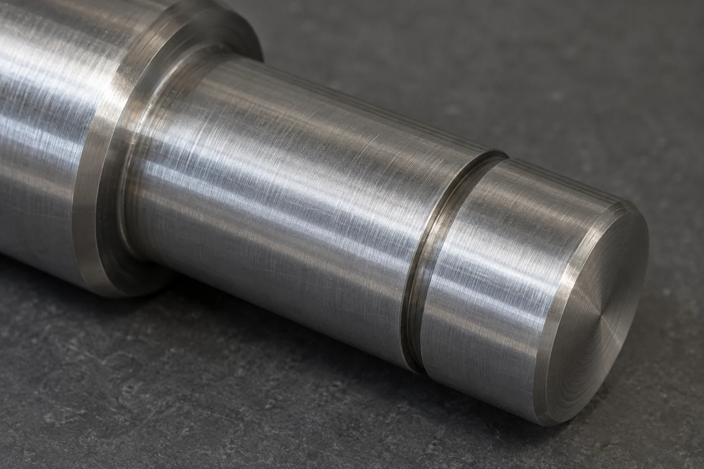
버·피막·부식과 재료 상태의 관리
버는 보기 싫은 가장자리만의 문제가 아닙니다. 홈 입구에 남은 버는 링을 들어 올리거나 완전 장착을 방해할 수 있고, 어깨면의 버는 부시를 떠받쳐 유격 계산의 기준을 바꿉니다. 떨어져 나온 작은 조각은 인접 베어링·씰과 접촉할 수 있으므로 조립 전에 기능면의 청정 상태도 확인합니다.
버 제거 과정에서 하중 측벽의 모서리를 과도하게 둥글리면 유효 지지 형상이 달라집니다. 따라서 모든 모서리를 같은 방식으로 크게 면취하는 지시는 적절하지 않을 수 있습니다. 비기능 모서리의 취급 안전 요구와 링이 닿는 모서리의 형상 한계를 나누어 표시하고, 작업 후 실제 프로파일을 확인합니다.
표면처리를 하면 홈의 실효 폭·지름과 링의 최종 두께가 달라질 수 있습니다. 링과 샤프트 양쪽에 처리가 있다면 어느 치수가 처리 전 값이고 어느 것이 처리 후 값인지 명시합니다. 피막을 포함한 링 두께와 홈 치수를 사용해 장착 여유를 검토하고, 다른 품번의 도금 두께 보정값을 그대로 적용하지 않습니다.
재료 변경은 강도·장착·환경을 함께 바꾼다
탄소강 링을 스테인리스 링으로 바꿀 때에는 부식만 비교하지 않습니다. 공급 상태와 탄성 한계, 장착 중 변형 허용 범위, 적용 하중·회전 조건이 달라질 수 있습니다. 샤프트와 링의 소재는 서로 독립적으로 지정하고, 소재 변경 후 기존 플라이어 설정과 장착 절차를 그대로 써도 되는지 확인합니다.
| 상태 또는 변경 | 잠재적 영향 | 관리할 내용 |
|---|---|---|
| 홈 입구·어깨의 버 | 미착좌·기준면 이동·이물 | 위치별 모서리 허용 상태 |
| 과도한 연마·면취 | 링 또는 부품의 접촉 영역 감소 | 최종 프로파일과 유효 지지면 |
| 링·축의 피막 | 홈 실효 치수·링 두께 변화 | 처리 전후 치수 구분 |
| 부식·피팅 | 접촉 상태·단면·분해성 변화 | 환경 조건과 검사 주기 |
| 링 소재·열처리 변경 | 장착 탄성과 용량 변화 | 품번·상태·승인 및 시험 기록 |
부식 환경에서는 물·염분·세척제·윤활제와 온도, 노출 시간을 구체적으로 적습니다. 홈처럼 틈이 있는 부위는 세척과 건조 상태가 외관만으로 보이지 않을 수 있습니다. 표면색이 같거나 모두 스테인리스라는 이유로 동일한 환경 적합성을 가정하지 말고 재료 등급과 실제 조합을 확인합니다.
처리 공정과 납품 상태
고강도 링에 산세나 전해 도금을 적용한다면 수소취성 관리가 필요한 공정인지 공급자와 확인합니다. 재료와 처리 조건에 따라 관리 필요성이 달라질 수 있습니다. 모든 도금품에 동일한 사후 가열 조건을 임의 지정하는 대신 소재 강도·처리 공정·적용 규격에 맞는 관리와 검증을 연결합니다.
입고 후 방청유·포장·보관 조건도 최종 조립과 연결합니다. 윤활이나 방청제를 제거해야 하는지, 남겨도 되는지, 기능 시험 전에 어떤 세척 상태를 재현할지 정합니다. 시험품만 특별히 깨끗하거나 다른 윤활 상태이면 양산품과의 비교가 어려워지므로 승인 조건과 납품 조건을 맞춥니다.
05장착과 치수 검사
링 장착과 완전 착좌의 확인
장착 전에 링 품번과 소재·표면 상태, 샤프트 홈의 최종 치수와 청정도를 확인합니다. 비슷한 크기의 링이 함께 보관되면 잘못된 두께나 계열이 섞일 수 있습니다. 부시·와셔를 넣은 뒤에도 링의 이동 경로와 플라이어 끝이 들어갈 공간이 남는지 실제 조립 순서로 확인해야 합니다.
축용 러그형 링은 해당 크기와 구멍에 맞는 플라이어로 필요한 만큼만 벌립니다. 축을 통과하는 데 필요한 범위 이상으로 변형하지 않도록 하고, 과대 벌어짐을 제한하는 공구를 검토합니다. 과도하게 벌려 영구변형이 생기면 복귀 후에도 의도한 장착 탄성을 확보하지 못할 수 있습니다.
공구 끝은 러그 구멍에 안정적으로 맞아야 하며, 링을 축방향으로 비틀어 당기는 방식은 피합니다. 링이 휘어진 채 홈에 들어가면 일부만 걸릴 수 있습니다. 장착이 유난히 어려운 경우에는 더 큰 힘을 쓰기 전에 품번·홈 폭·버·피막과 공구 설정을 확인하여 원인을 나눕니다.
링의 방향은 제품별 지시로 정하기
프레스 링에는 가공 과정에 따른 모서리 차이가 있을 수 있지만, 날카로운 면은 언제나 특정 방향이라는 규칙을 모든 링에 적용하지 않습니다. 링 계열, 단면, 하중 방향과 공급자의 지시에 따라 필요한 방향을 정합니다. 경사형·물결형·스파이럴형은 같은 앞뒤 규칙으로 묶을 수 없으므로 방향이 중요하면 조립도에 면 또는 표식으로 표시합니다.
| 장착 단계 | 확인 내용 | 의심스러운 징후 |
|---|---|---|
| 조립 전 | 품번·최종 홈·이물·공구 적합성 | 다른 두께 혼입·버·피막 뭉침 |
| 벌림과 이동 | 필요한 변형량·평면 유지 | 과대 벌어짐·비틀림·러그 손상 |
| 놓기 | 홈 위치와 원주 방향 맞물림 | 한쪽 들뜸·일부만 홈에 진입 |
| 장착 후 | 지정 방향 착좌·간섭·유격 | 국부 틈·기울기·비정상 유격 |
| 분해 후 | 링과 홈의 손상·재사용 조건 | 잔류 변형·균열·모서리 손상 |
플라이어를 놓았다는 것만으로 조립을 완료하지 않습니다. 접근 가능한 둘레에서 링이 홈에 들어간 상태와 들뜬 부분을 확인하고, 제품 지침에 맞는 방법으로 착좌를 검사합니다. 공구 구멍 사이 간격이나 소리 하나만으로 판정하지 말고 관찰 위치와 합격 상태를 작업 표준에 명확히 정합니다.
장착 판정과 분해 후 관리
링을 자유롭게 돌릴 수 있는지를 보편적인 합격 시험으로 삼지 않습니다. 장착 탄성·마찰·표면 상태가 회전에 영향을 주며, 회전 가능 여부가 모든 둘레의 맞물림을 직접 보증하지는 않습니다. 완전 착좌와 부시 유격, 주변 부품 간섭을 각각 확인해야 서로 다른 문제를 구분할 수 있습니다.
분해한 링의 재사용 가능 여부는 해당 제품과 사용 조건의 지침으로 정합니다. 한 번 사용했다고 무조건 재사용하거나, 반대로 모든 링을 같은 횟수 기준으로 폐기하지 않습니다. 손상·영구변형·부식이 있거나 장착 이력이 불명확하면 승인 절차에서 처리하며, 분해 중 홈 측벽이 찍히지 않았는지도 함께 살펴봅니다.
치수·형상 검사와 측정 기준
검사 계획은 측정기 목록보다 기능 치수에서 시작합니다. 홈 바닥 지름·폭·위치와 어깨면의 관계, 바닥 반경과 모서리 상태를 각각 무엇으로 확인할지 정합니다. 링이 들어간다는 기능 확인은 유용하지만, 너무 넓은 홈이나 부족한 끝단 여유까지 자동으로 판정하지는 못합니다.
좁은 홈 바닥 지름은 일반 캘리퍼의 접촉부가 제대로 닿지 않을 수 있습니다. 측정 팁의 폭과 반경이 홈에 맞는지, 실제 바닥이 아니라 입구 모서리에 걸리지 않는지 먼저 확인합니다. 홈 측정용 접촉자나 적합한 광학 방법 등을 검토하고, 측정 원리와 접촉 위치가 도면의 치수 정의와 일치하는지 검증합니다.
홈 폭도 입구에서 보이는 폭과 링이 실제로 차지하는 깊이의 폭이 다를 수 있습니다. 측벽 기울기·버·바닥 반경 때문에 측정 위치에 따라 결과가 바뀔 수 있으므로 어느 높이에서 폭을 정의하는지 정합니다. 필요한 경우 단면 프로파일을 함께 확인해 숫자가 맞아도 링이 안착하지 않는 원인을 찾습니다.
단품 치수와 조립 결과를 연결하기
어깨면부터 홈 측벽까지의 거리는 기능 기준면을 재현해 측정합니다. 축 끝면을 기준으로 따로 측정한 두 치수의 차로 계산할 수도 있지만, 각 측정의 불확도와 기준면 상태가 결과에 들어갑니다. 중요 기능 치수는 직접 측정 가능한지 검토하고, 불가능하면 계산 경로를 검사 성적서에서 추적할 수 있게 합니다.
| 검사 대상 | 가능한 접근 방법 | 주의할 오판 |
|---|---|---|
| 홈 바닥 지름 | 맞는 접촉자·광학 또는 형상 측정 | 팁이 입구에 걸린 값을 바닥 지름으로 기록 |
| 홈 폭·측벽 | 폭 측정과 프로파일 확인 | 입구 폭만으로 깊은 위치의 폭을 보증 |
| 어깨–홈 거리 | 기준면을 이용한 직접 또는 추적 가능한 간접 측정 | 홈 중심과 하중 측벽을 혼동 |
| 반경·버 | 확대 관찰·형상 비교·필요한 단면 | 버 제거 후 지지 모서리 손상을 놓침 |
| 조립 유격 | 정해진 착좌·측정력에서 변위 확인 | 탄성 변형을 자유 유격으로 해석 |
샤프트를 돌려 여러 방향에서 측정하면 국부 손상이나 형상 차이를 찾는 데 도움이 되지만, 모든 형상 공차가 몇 개의 지름 측정으로 보증되지는 않습니다. 원형도·원통도·동축 관계·끝면 방향 중 무엇이 실제 기능에 필요한지 정하고, 그 요구를 확인할 수 있는 측정 전략을 선택합니다.
측정의 일관성과 링 입고 검사
측정기는 표시 분해능뿐 아니라 접근성·반복성·측정력·고정 상태와 온도 영향을 함께 검토합니다. 공차에 비해 측정 불확도가 크면 합격과 불합격의 경계에서 결과가 흔들릴 수 있습니다. 측정자와 장비가 달라도 같은 기능 치수를 비교할 수 있도록 기준 부품 또는 상호 비교 절차를 정합니다.
링 자체의 입고 검사는 공급자 검사 정의와 맞춥니다. 자유 상태 지름은 이미 장착한 링에서 측정한 값과 같다고 볼 수 없으며, 다른 링 계열에 동일한 측정법을 적용하지 않습니다. 특히 러그형 링과 E형 링은 접촉하는 형상이 다르므로 측정 위치와 방법을 품번별로 확인합니다.
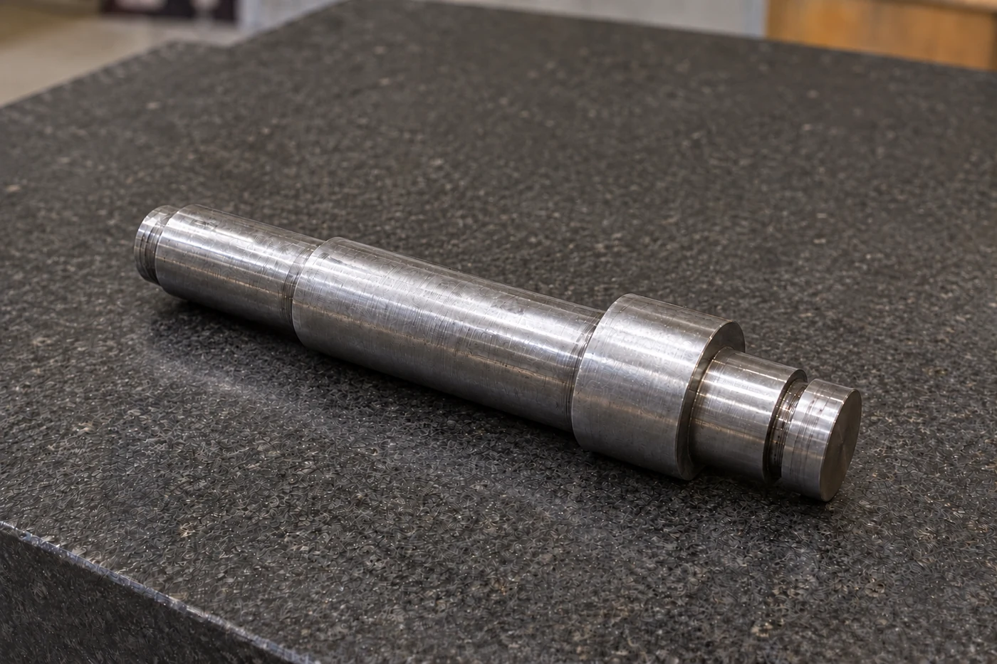
06기능 검증과 제작 의뢰
조립체 유지력 시험과 고장 원인 분석
치수 합격은 기능 검증의 출발점입니다. 최종 조립체가 필요한 축방향 힘을 지지하는지 확인하려면 시험 하중의 방향과 속도, 지그의 접촉 위치, 유지 시간과 측정 항목을 정해야 합니다. 생산품에서 어깨면이 받는 힘을 시험 중 링이 받게 만들면 서로 다른 구조를 비교하는 셈이 됩니다.
시험 지그는 실제 부시나 와셔의 접촉 범위를 재현해야 합니다. 링 전체를 넓은 판으로 이상적으로 받쳐 주는 지그와 실제 좁은 끝면은 같은 조건이 아닐 수 있습니다. 샤프트 고정 위치도 끝단 재료를 추가로 받쳐 주거나 휘게 만들 수 있으므로 자유물체도와 단면을 이용해 시험 경로를 확인합니다.
합격 기준에는 링이 빠지지 않는 것 외에 영구 유격 증가, 링의 잔류 변형, 홈 측벽 손상과 부시 이동 제한을 포함할 수 있습니다. 무엇을 허용할지는 사용 요구에서 정합니다. 시험 하중을 제거한 후 다시 치수와 착좌 상태를 확인해야 탄성 변위와 영구변형을 구분할 수 있습니다.
불량의 위치를 따라 원인을 나누기
하중을 반복하거나 회전시켜야 하는 제품은 정적 시험 뒤에 실제 사용 조건을 대표하는 검증을 연결합니다. 속도·하중·온도를 각각 따로 확인한 결과만으로 동시에 작용하는 조건을 모두 보증하지 않습니다. 필요한 조합과 반복 횟수, 환경 노출 전후 비교는 사용 시나리오와 변경 위험에 따라 정합니다.
| 관찰 결과 | 가능한 원인 범주 | 구분에 필요한 증거 |
|---|---|---|
| 링이 한쪽만 들뜸 | 부분 장착·버·비틀림·간섭 | 원주 관찰·홈 프로파일·장착 이력 |
| 홈 측벽이 눌림 | 홈 소재·접촉 집중·하중 초과 | 재료 상태·접촉 흔적·시험 경로 |
| 링의 잔류 벌어짐 | 조립 과변형·회전·과하중 | 미사용품 비교·공구 설정·운전 기록 |
| 유격이 계속 증가 | 마모·영구변형·부품 미착좌 | 전후 치수·분해 관찰·하중 이력 |
| 어깨 부근 균열 | 국부 형상·표면 결함·복합 하중 | 균열 기점·재료·축 응력 평가 |
불량 링을 다시 끼워 정상처럼 보이게 만든 뒤 원인을 찾으면 중요한 증거가 사라질 수 있습니다. 가능하면 분해 전에 방향·위치·유격과 접촉 흔적을 기록하고, 링·축·부시를 같은 조립체 번호로 보관합니다. 파손면을 세척하거나 연마하기 전에 어떤 분석이 필요한지도 검토합니다.
생산 검사와 변경 후 확인
전수 확인할 항목과 표본으로 검증할 항목은 성격이 다릅니다. 품번 혼입·장착 누락·눈에 보이는 들뜸은 조립 공정에서 관리하고, 파괴 유지력 시험이나 장시간 내구 시험은 별도의 시편과 계획이 필요할 수 있습니다. 검사 빈도와 표본 수는 생산 규모·공정 안정성과 요구 신뢰도에 맞춰 정합니다.
승인 이후에도 링 공급자·소재·피막·홈 공구·열처리·버 제거 방법이 바뀌면 영향을 검토합니다. 치수 표에 변화가 없어도 접촉면과 장착 거동이 달라질 수 있습니다. 변경된 항목과 연결된 측정·시험만 다시 확인하되, 비교 기준으로 사용할 승인품의 도면과 검사 기록을 유지합니다.
제작 도면·견적 요청에 담을 정보와 참고 자료
제작 요청에는 샤프트 단품도와 링·부시가 포함된 조립도를 함께 전달하는 편이 좋습니다. 단품도에는 홈 치수가 있어도 왜 그 위치가 중요한지 보이지 않을 수 있습니다. 조립도에 하중 방향과 기능 기준면, 허용 유격과 주변 간섭 영역을 표시하면 제조와 검사에서 우선 관리할 항목을 정하기 쉽습니다.
링은 명목 축 지름 하나가 아니라 규격 판·계열·품번·소재·피막을 포함해 식별합니다. 대체품을 허용한다면 어떤 항목이 같아야 하고 어떤 검증을 다시 할지 명시합니다. 샤프트의 최종 치수 상태와 열처리·표면 요구, 홈 모서리 제한과 기능면의 외관 판정도 같은 개정 도면에 연결합니다.
| 자료 묶음 | 포함할 내용 | 결정에 도움이 되는 이유 |
|---|---|---|
| 구조·사용 조건 | 단품도·조립도·하중 방향·회전·온도 | 실제 하중 경로와 검증 범위 확정 |
| 링 구매 사양 | 규격 판·계열·품번·소재·표면 | 혼입 및 임의 대체 방지 |
| 샤프트 기능 치수 | 홈 지름·폭·위치·끝단 여유·어깨 | 가공 기준과 측정 계획 연결 |
| 품질 기준 | 허용 유격·착좌·모서리·기능 시험 | 치수 합격과 조립체 승인 연결 |
| 공급 조건 | 수량·시제품 일정·단품/조립체·성적서 | 제조 범위와 승인 단계 협의 |
샘플만 있는 경우에는 샘플의 측정값과 설계 허용값을 구분합니다. 사용품의 홈에는 마모나 눌림이 있을 수 있고, 링은 장착 이력으로 자유 상태가 달라졌을 수 있습니다. 여러 샘플의 치수 분포와 원래 사용 조건을 함께 확인하여, 관찰된 치수를 그대로 공차 중심으로 삼지 않도록 합니다.
검토 결과는 부품 제작 가능성뿐 아니라 필요한 추가 자료와 승인 단계로 정리합니다. ID METAL에 문의할 때에는 도면·소재·수량·사용 조건과 필요한 검사 범위를 함께 전달해 공급 범위를 협의할 수 있습니다. 이 글의 공정 예시는 일반적인 검토 항목이며 특정 장비 보유·가공 한계·성능 보증을 의미하지 않습니다.
승인 샘플을 양산 기준으로 연결하기
시제품 승인에서는 대표적인 평균 치수뿐 아니라 조립에 불리한 한계 조합을 어떻게 확인했는지 기록합니다. 시험에 사용한 링 품번·샤프트 상태·부시 길이와 지그 조건을 남기면 양산에서 차이가 발생했을 때 원인을 좁힐 수 있습니다. 승인 샘플의 외관만 남겨 두는 것보다 기능 치수와 시험 조건을 함께 보존하는 편이 유용합니다.
개정 도면과 최종 전달 자료
도면 개정 뒤에는 링·샤프트·부시 중 어느 부품이 바뀌었는지뿐 아니라 조립 관계가 어떻게 달라졌는지 확인합니다. 홈을 옮기면 유격과 끝단 여유가 동시에 달라질 수 있고, 와셔를 추가하면 지지와 길이 공차가 함께 바뀝니다. 변경 검토의 단위를 단품 치수에만 두지 않고 완성 조립체까지 연결합니다.
최종 전달 자료에는 적용 도면과 링 사양, 검사 방법·기준, 기능 검증 결과와 미해결 조건을 함께 정리합니다. 필요한 치수를 만들 수 있는지와 그 치수로 조립 기능이 성립하는지는 연결된 두 질문입니다. 이 관계를 설계·제조·검사가 공유해야 후속 발주와 부품 교체에서도 같은 기준을 유지할 수 있습니다.
English Edition · Shaft Retaining-Ring Groove and Shoulder Design
Shaft retaining-ring groove design involves more than making a recess that accepts a ring. The shoulder, sleeve or washers, ring and groove flank must form a defined axial load path. Assembly endplay, rotational conditions and the dimensions remaining after manufacture must work together. Even a small groove can govern retention when its edges or supporting end land are unsuitable.
This article focuses on external shaft rings of the DIN 471 family, connecting their geometry to manufacturing and inspection. Photographic illustrations and interactive 3D models explain assembly, the groove and shoulder section, and axial endplay. They are conceptual examples, not supplied products, customer drawings, validated stress analyses or universal acceptance limits.
Surfaces that carry the load
Follow the shoulder, sleeve, ring and groove flank, and distinguish ring capacity from groove capacity.
Dimensions and assembly endplay
Connect groove diameter, width, end land, fillets, chamfers and tolerance accumulation.
From machining to verification
Translate heat treatment, burrs, finishes and installation into drawings and assembly qualification.
01Retention arrangement and ring selection
Axial retention between a shoulder and a ring
The starting point of shaft retaining-ring groove design is the movement that the assembly must prevent. The basic arrangement here comprises a stepped shaft, a sleeve fitted over it and an external retaining ring beyond the sleeve. The shaft shoulder and ring provide opposing axial stops, while the cylindrical fit separately guides the sleeve.
When the sleeve is pushed toward the shaft end, its end face, or an intermediate washer, presses on the ring. The ring transfers the reaction into the loaded groove flank and the shaft material behind it. Loading toward the shoulder instead passes through the sleeve end face into the shoulder. These opposite directions therefore have different contact paths.
The exposed part of the ring blocks the sleeve, while the part engaged in the groove transfers force into the shaft. A visible ring is not proof of adequate engagement. A ring caught on only part of the groove, or resting against an excessive chamfer, may look installed without establishing the intended contact geometry.
Separate axial retention from torque transmission
Installing a flat retaining ring does not by itself lock the sleeve rotationally to the shaft. Torque transmission needs a separate feature, such as a key, spline or designed interference fit. Likewise, the ring’s elastic grip on the shaft does not establish axial preload in the sleeve stack. Radial installation elasticity and axial clamping force are separate quantities.
| Component | Main function | Interfaces to examine |
|---|---|---|
| Shaft shoulder | Axial stop in one direction | Sleeve end face and fillet clearance |
| Sleeve and washers | Transfer load and establish stack length | Effective face bearing against the ring |
| External retaining ring | Prevent escape in the opposite direction | Sleeve contact and groove-flank contact |
| Groove and end land | Support the ring reaction | Loaded flank, root and end margin |
A bearing arrangement requires more definition than the sleeve example. A ring locating an inner bearing ring on a shaft acts at a different interface from a ring locating an outer ring in a housing. The assembly drawing must identify the bearing ring being supported, clearances between moving and stationary parts, and any axial movement the bearing arrangement requires.
Read the actual contact sequence and the model
Start the design review by marking actual contact surfaces and load arrows on a section. Where gaps exist, all interfaces do not carry load simultaneously. Following the order in which gaps close and surfaces make contact explains what changes when a washer is added or the groove is moved.
The interactive models are conceptual views of these interfaces. Assembly stages show ring expansion and recovery; the section shows groove engagement and shoulder clearance; the endplay model shows available axial movement. Enlarged gaps and edge details aid understanding and must not be treated as drawing dimensions or load-analysis results.
External, internal, E-type and spiral rings
The names snap ring, circlip and retaining ring are used broadly. Establish the mounting location and ring family before defining the groove. DIN 471 covers shaft rings and DIN 472 covers bore rings. Identify the applicable standard and edition, then confirm the required groove and ring dimensions from the approved drawing for the selected part.
A typical lugged external ring is expanded using its tool holes, passed axially over the shaft end and released into the groove. An internal ring is compressed, inserted into the housing and released into an internal groove. Both use elastic deformation, but the direction of deformation, groove diameter and tool-access requirements differ.
An E-type ring is installed radially into the shaft groove from the side. Confusing this motion with installation of a lugged external ring can twist or damage the latter. Matching nominal shaft diameters does not establish interchangeable grooves, projections, loads or rotational limits.
Groove compatibility does not establish full equivalence
Spiral rings are wound from wire; manual installation typically starts with one end in the groove and continues by winding the ring around it. A lugged-ring installation procedure does not apply to a ring without plier holes. Some series are supplied for existing standard grooves, so substitution requires the relevant manufacturer interchange data and part drawing.
| Ring family | Location and installation | Checks before substitution |
|---|---|---|
| Lugged external | Outside a shaft / expanded, then moved axially | Groove, lug clearance and rotation |
| Lugged internal | Inside a housing / compressed, then moved axially | Internal groove, access and housing support |
| E-type | Outside a shaft / installed radially | Specified groove, assembly direction and retention |
| Spiral | Shaft or bore / winding or a specified tooling method | Turns, groove compatibility, installation and removal |
Flat rings must also be distinguished from products designed to compensate endplay. Certain waved, bowed or beveled designs provide axial spring force or wedging action, but those functions are not universal properties of flat standard rings. If clearance compensation is required, first establish that the selected ring geometry and mating interfaces are designed for it.
Part identification and assembly sequence
The purchasing specification should connect the standard edition and size to the applicable series, material, finish and manufacturer part number. An approved drawing referencing an earlier edition must not be changed simply because a newer edition exists. Differences between current reference information and the contractual drawing require an agreed revision decision.
The assembly model represents the lugged external family. Observe the sleeve moving to the shoulder, the ring opening enough to pass the shaft, its axial movement to the groove and its release. The ability to rotate the model on screen says nothing about whether the physical ring may move relative to the shaft during operation.
From the shaft end to the retaining groove
INTERACTIVE 3DThe ring contracts into the groove. The shoulder and ring limit axial sleeve travel; they do not lock its rotation.
02Loads and groove design
Assess ring strength and groove support separately
Do not select a retaining arrangement from one prominent catalog load figure. Ring failure and deformation of the supporting groove are different limiting conditions. Evaluate the applicable ring and groove capacities separately and treat the lower condition as a design limit. Also establish whether the preliminary method accounts for dynamic and eccentric loads.
A hard ring on a comparatively soft shaft may deform the groove flank or end land before the ring breaks. Even with adequate groove support, ring bending, twisting or contact with the retained component can limit the arrangement. Confirm the actual shaft condition and properties at the load-bearing region, rather than matching a material name alone.
Catalog static loads must be read with their material, groove and contact assumptions. A value with an embedded safety factor differs from a threshold for initial permanent deformation or ultimate failure. Do not apply one factor indiscriminately to ring and groove, or compare manufacturers’ figures without their definitions.
Repeated loads, impact and rotation require separate inputs
A reciprocating component or one subject to reversing loads may travel through its clearance before striking a stop. Average axial force alone does not describe that event. Record peak load, direction, duration, repetitions, moving mass and speed before contact to determine which verification is needed beyond a static calculation.
| Condition | Required input | Result to assess |
|---|---|---|
| Static axial load | Maximum force, direction and contact geometry | Separate margins for ring and groove |
| Repeated or reversing load | Load history, endplay and repetitions | Wear, permanent clearance change and cracks |
| Impact | Mass, contact speed and stopping mechanism | Ring lift, groove damage and residual deformation |
| Rotation | Normal and maximum speed, acceleration and imbalance | Ring expansion, engagement and interference |
| Combined loading | Shaft bending, torsion and axial force | Section strength and fatigue at the groove |
An external ring on a rotating shaft requires assessment of centrifugal expansion. Sufficient expansion can lift it from the groove, making installed condition and ring family relevant alongside speed. Adequate static axial retention does not establish adequate rotational performance. Review speed-critical applications against the manufacturer data for the specific product.
Shaft fatigue and definition of service conditions
For a shaft carrying bending and torsion, the groove combines a reduced section with a geometric discontinuity. Passing an axial-retention check does not complete the shaft-fatigue assessment. Evaluate the actual geometry, including proximity to shoulders, keyways and holes, surface defects, heat treatment and residual stresses where relevant.
Where duty information is missing, list the required inputs before assigning calculation values. Define which operating and abnormal-stop conditions must be met, the replacement interval and whether any permanent deformation is permissible. Those requirements then provide a common basis for manufacturer review and prototype testing.
Groove diameter, width, root radius and end margin
External-groove depth follows from the shaft and groove-root diameters. For concentric cylinders, radial depth t = (shaft diameter d − groove-root diameter dg) / 2. Treating the diameter difference as the depth introduces a factor-of-two error. Specify the governing diameters and tolerances, and avoid contradictory depth and diameter requirements on the drawing.
A deeper groove is not automatically safer. It changes engagement, the remaining shaft section and the ring’s installed elastic condition at the same time. A shallow groove may instead reduce seating or engagement. Start with the specified groove for the selected ring, and review any depth change with both the ring supplier and the shaft design.
Groove width provides installation space and allows axial ring movement. Too little space can prevent full seating with limiting combinations of burrs, finish and ring thickness; additional width can add ring movement to assembly endplay. If loads alternate between both flanks, the drawing must be particularly clear about which flank controls each function.
Examine the root and the loaded flank together
The root radius must be compatible with the ring section. An excessive radius can prevent full seating or reduce effective support on the loaded flank; an arbitrarily sharp root can aggravate the shaft notch. Assess ring seating and shaft stress concentration together to establish a profile that satisfies both requirements.
| Feature | Functional connection | Drawing and inspection definition |
|---|---|---|
| Groove-root diameter | Engagement, installed elasticity and remaining shaft section | Final diameter and tolerance |
| Groove width | Installation and axial ring movement | Minimum and maximum width; reference flank |
| Loaded flank | Transfers the ring reaction | Location, orientation and edge limits |
| Root radius | Ring seating and shaft notch effect | A profile compatible with the selected ring |
| End margin | Supports the groove from behind | Distance to the free end or actual support boundary |
The end margin is the material remaining between the loaded groove flank and the shaft end or another boundary that removes support. A thin land requires assessment of its shear and bending resistance. A cross-hole or large end chamfer can reduce the effective support even when the overall shaft length appears generous.
End-land support and functional dimensions
A catalog end margin belongs to a particular ring and set of assumptions. Do not transfer the minimum distance unchanged to a different material, condition or load direction. A groove far from the end face may still be supported by a thin hollow wall. The section drawing must expose the actual volume of material carrying the reaction.
Controlling only the groove center allows the functional flank to move with groove-width variation. If shoulder-to-loaded-flank distance controls the assembly, consider a dimensioning scheme that directly controls that relationship. Using the same functional surfaces for machining references and inspection makes the design intent easier to verify.
03Shoulders and axial endplay
Shoulder fillets and mating chamfers
A shaft shoulder is an axial reference surface that must actually contact the sleeve or bearing ring. A large shoulder diameter does not guarantee a large effective support area because the mating bore and chamfer remove part of that area. Face tilt or a local high spot can also concentrate contact on a small region.
The fillet is the rounded transition from the shaft seat to the shoulder. If the mating bore chamfer or relief does not clear it, the component can stop on the fillet before its end face reaches the shoulder. This changes the axial reference and may introduce tilt even when the assembly appears nearly flush.
Bearing manufacturers provide product-specific abutment dimensions and permissible fillets. Clearance and adequate support must be satisfied together, and values from a different bearing should not be copied because its size looks similar. Distinguish the bearing’s own chamfer specification from the permitted shaft fillet and check the actual mating geometry.
Why enlarging a chamfer is not a complete solution
A larger chamfer can clear the shoulder fillet while reducing the supporting end-face area. At the ring end, excessive chamfering can move the applied contact farther out on the ring. Check shoulder-fillet clearance and the ring-side load introduction separately; they involve different faces and different geometric constraints.
| Interface | Geometry to examine | Possible observation |
|---|---|---|
| Shoulder side | Clearance between fillet envelope and bore chamfer | Unseated face, tilt or increased assembly length |
| Ring side | Effective component contact height | Localized ring contact and deformation risk |
| Intermediate washer | Inner relief and outer supporting region | Washer bending or interference with moving parts |
| Complete assembly | Face orientation and running clearances | Eccentric contact, rubbing or variable position |
Where the shaft needs a larger fillet, a relieved spacer or another support arrangement may be considered. Adding a spacer also adds length tolerances and interfaces, and its own compression and bending require assessment. A thin washer that clears the fillet does not automatically provide an adequate structural abutment.
Machining relief and functional surfaces
An undercut can provide grinding clearance or avoid an interfering transition, but it removes material. Its introduction therefore requires a renewed review of the local section and stress concentration. Evaluate the machining relief with the shaft’s bending and torsional load paths so that improving seating does not compromise another function.
Define the functional face orientation, fillet or relief, mating chamfer and contact region alongside shoulder size. Apply controls to the surfaces that govern axial location and load transfer rather than tightening every tolerance indiscriminately. The section model helps explain these relationships; it does not replace dimensional verification.
Groove walls, root, end land and shoulder clearance
INTERACTIVE 3DTeal identifies the two groove flanks. Loading toward the free end seats the ring against the right flank. The ring is omitted and only part of the sleeve is shown.
Axial endplay, tolerance accumulation and thermal growth
Axial endplay is the distance the sleeve can actually move from the shoulder toward the ring. Groove width minus ring thickness does not describe the complete assembly clearance. The calculation also requires shoulder-to-supporting-flank distance, sleeve and washer lengths, and the seating condition at every interface.
Consider a simple model with a flat ring against the outboard loaded flank and parallel end faces. Let L be the distance from the shoulder to that flank, s the ring thickness, and B the total sleeve-and-washer length. Then E = L − s − B. L is neither the groove-center distance nor the distance to the inboard flank; changing its definition changes the equation.
This is a geometric relation describing clearance and its sign. Positive E represents idealized travel; negative E indicates overlap that rigid components cannot accommodate as drawn. A negative value must not be interpreted directly as useful preload. Preload requires additional information about elastic load–deflection behavior and actual contact conditions.
Calculate the minimum and maximum endplay
For an independent limit stack, Emin = Lmin − smax − Bmax and Emax = Lmax − smin − Bmin. An assembly that works at nominal dimensions may be unassemblable or too loose at a limit combination. First map the dimension scheme so that correlated or shared dimensions are not counted twice.
| Variable | Effect of an increase | Control consideration |
|---|---|---|
| L: shoulder to loaded flank | Increases clearance | Do not confuse it with groove-center location |
| s: ring thickness | Decreases clearance | Use the final finished condition |
| B: sleeve and washer stack | Decreases clearance | Include individual lengths and seating faces |
| Incomplete face seating | Invalidates the simple geometric state | Check burrs, fillet interference and debris |
| Operating-temperature change | Changes relative lengths | Consider materials, temperature distribution and constraints |
Temperature can change the shoulder-to-groove distance differently from the retained stack. A first approximation for freely expanding parts at uniform temperatures is ΔE ≈ ΔL − Δs − ΔB. Unequal component temperatures or external constraints require a more complete thermal and structural assessment. Room-temperature clearance alone does not establish the operating condition.
Clearance adjustment and measurement conditions
Shimming, selective thickness assembly and dedicated clearance-compensating rings require different controls. Shims add components and combination records; selective assembly requires control of supply lots and replacement compatibility. Elastic compensation must maintain the required force over its working range and cannot simply be treated as elimination of flat-ring location tolerances.
In the endplay model, change one variable at a time to see which gap responds. In physical inspection, distinguish the force that seats the ring against the specified flank from the force used to move the sleeve. Excessive measurement force can bend components or lift the ring, measuring elastic displacement as well as free endplay.
How the stack length changes axial endplay
INTERACTIVE 3DA small positive example of E = L − s − B: distance from the shoulder to the loaded groove wall minus ring thickness and stack length. Flat bearing faces and a ring held against that wall are assumed.
04Machining sequence and surface quality
Shaft machining, heat treatment and final finishing
A useful manufacturing review starts with the shaft’s final service condition and works backward through the route. Material condition, heat treatment, bearing-seat grinding, plating and cleaning influence when the groove should be finished. Dimensions that conform immediately after turning may change later, so the final inspection stage must match the drawing requirement.
Define the references used to machine the outside diameter, shoulder and groove. Producing related features in one setup can reduce reference transfers where the process allows, but part length, support stiffness and later heat treatment may require another setup. Document how those references will be recovered and how the functional shoulder-to-groove distance will be verified.
A grooving tool must be selected for corner radius and side geometry as well as width. Matching insert width alone does not ensure the required root profile or flank form. Check actual insert dimensions, tolerances and mounting, and verify the operation that establishes the final profile when roughing and finishing are separate.
Distinguish in-process dimensions from final dimensions
A slender or long shaft can deflect under cutting forces and workholding. Groove geometry measured in the fixture may differ after release, making support position and clamping force relevant process variables. If wear, trapped chips or chatter appears, examine its effect on groove width and root form before relying on a dimensional offset alone.
| Process stage | Review points | Information passed forward |
|---|---|---|
| Material and roughing | Material condition, references and distortion allowance | Material identity and intermediate dimensions |
| Heat treatment | Required hardness, treated region and distortion | Finishing allowance and inspection locations |
| Groove and shoulder finishing | Functional distance, width and root profile | Final dimensional and form records |
| Deburring and cleaning | Preserved load-bearing edges and removal of debris | Defined permissible edge condition |
| Finishing and final inspection | Coated dimensions, corrosion protection and seating | Results for the final supplied condition |
Finishing the groove before heat treatment and finishing it afterward present different tradeoffs. The former requires control of subsequent distortion; the latter requires assessment of machining hardened material, tool access and the required surface condition. Select the sequence from material, treatment coverage and dimensional requirements rather than applying one route to every shaft.
Hardened layers and production variation
For a surface-hardened shaft, establish the condition remaining at the groove root and flanks. Cutting a groove after hardening can remove the intended surface layer; treating an existing groove requires review of the treatment response at that geometry. This is why the specified locations, depth and measurement method matter alongside a hardness value.
Track tool changes and offsets so that process changes remain traceable. Variation in groove width may have a different cause from drift in groove position. Comparing functional dimensions on initial pieces, after tool changes and during suspected process variation helps connect part conformance with assembly endplay.
Burrs, finishes, corrosion and material condition
Burrs affect function as well as appearance. A burr at the groove opening can lift the ring or prevent full seating, while a shoulder burr can hold the sleeve off its reference face and invalidate the endplay stack. Detached debris can reach adjacent bearings or seals, making cleanliness of the functional surfaces part of assembly readiness.
Aggressive deburring can round the loaded groove edge and change its effective support. A blanket instruction to heavily break every edge may therefore be unsuitable. Separate handling requirements on nonfunctional edges from profile limits at ring-contact edges, and verify the resulting geometry after the operation.
Finishing can change effective groove width, diameter and final ring thickness. If both shaft and ring are treated, identify which requirements apply before and after finishing. Assess installation clearance using the finished ring and groove dimensions, without transferring a plating allowance from a different part.
Material changes affect strength, installation and environment
Replacing a carbon-steel ring with stainless steel is not solely a corrosion decision. Supply condition, elastic limits, allowable installation deformation, load and speed suitability can differ. Specify shaft and ring materials independently and confirm whether the existing plier setting and installation procedure remain appropriate after substitution.
| Condition or change | Potential effect | Control requirement |
|---|---|---|
| Burrs at groove or shoulder | Incomplete seating, reference shift or debris | Location-specific edge condition |
| Excess polishing or chamfering | Reduced ring or component contact | Final profile and effective support |
| Shaft and ring finish | Changed groove size and ring thickness | Before- and after-finish dimensions |
| Corrosion or pitting | Changed contact, section or removability | Exposure conditions and inspection interval |
| Ring material or condition change | Changed installation elasticity and capacity | Part identity, condition, approval and test records |
Describe corrosion exposure in terms of water, salts, cleaning agents, lubricants, temperature and duration. Cleaning and drying inside a groove or narrow gap may not be apparent from appearance alone. Similar color, or the generic label stainless steel, does not establish equivalent environmental suitability; confirm the actual grades and material combination.
Processing and supplied condition
If acid cleaning or electroplating is proposed for a high-strength ring, establish with the supplier whether hydrogen-embrittlement controls are required. The need depends on material and processing conditions. Link controls and verification to material strength, process and applicable specification rather than assigning one post-treatment schedule to every plated part.
Connect preservation oil, packaging and storage conditions to final assembly. Define whether protective products must be removed or retained and which cleaning condition the functional test must reproduce. A specially cleaned or differently lubricated test specimen may not represent production, so approval and supplied conditions should be aligned.
05Installation and dimensional inspection
Ring installation and verification of full seating
Before installation, verify ring identity, material and finish, together with final groove dimensions and cleanliness. Storage of similar sizes can allow thicknesses or families to be mixed. Follow the real assembly sequence to confirm that the ring’s travel path and access for the plier tips remain available after sleeves and washers are fitted.
Expand a lugged external ring with pliers suited to its size and holes, only far enough to pass the shaft. Consider tooling that limits excessive expansion. If installation produces permanent set, the ring may fail to recover the intended installed elastic condition after release.
The tool tips must engage the lug holes securely without twisting the ring out of its plane. A distorted ring may engage only part of the groove. If installation is unexpectedly difficult, investigate part identity, groove width, burrs, finish and tool setting before increasing force.
Determine orientation from the specific product instructions
Stamped rings may have different edge conditions on their two faces, but a universal sharp-edge orientation rule must not be applied to every ring. Determine orientation from the family, section, loading and supplier instructions. Beveled, waved and spiral products cannot share one assumed front-to-back rule; identify a face or mark on the assembly drawing where orientation matters.
| Stage | Check | Suspicious indication |
|---|---|---|
| Before assembly | Part identity, final groove, cleanliness and tool fit | Mixed thickness, burr or finish accumulation |
| Expansion and transfer | Necessary deformation and ring flatness | Overexpansion, twisting or lug damage |
| Release | Groove alignment and circumferential engagement | One side raised or partial engagement |
| After installation | Specified seating, interference and endplay | Local gaps, tilt or abnormal clearance |
| After removal | Damage and permitted reuse conditions | Permanent set, cracks or edge damage |
Releasing the pliers does not complete verification. Inspect accessible portions of the circumference for engagement and lifted regions, using the seating check required by the product instructions. Do not rely solely on lug spacing or an audible click; define viewing locations and the acceptable state in the work instruction.
Acceptance after installation and removal
Do not use the ability to rotate the ring freely as a universal acceptance test. Installed elasticity, friction and finish affect rotation, and rotational freedom does not directly prove engagement around the circumference. Check full seating, sleeve endplay and surrounding interference separately so that different problems remain distinguishable.
Permitted reuse depends on the product and service instructions. Neither automatic reuse nor a universal discard count is appropriate for all rings. Handle damage, permanent set, corrosion or uncertain installation history through the approved procedure, and inspect the groove flank for marks introduced during removal.
Dimensional inspection and measurement references
An inspection plan begins with functional characteristics rather than an instrument list. Define how groove-root diameter, width, location, shoulder relationships, root radius and edges will be checked. A ring-fit check is useful, but it does not automatically detect an excessively wide groove or inadequate end margin.
Ordinary caliper jaws may not reach a narrow groove root correctly. Confirm that tip width and radius fit the groove and do not bridge the opening edges. Consider suitable groove contacts or optical methods, and verify that the measurement principle and contact locations correspond to the dimension defined on the drawing.
The width visible at a groove opening can differ from the width available at the ring’s working depth. Flank taper, burrs and root radii can make the reading depend on measurement location. Define the relevant height and, where necessary, examine the section profile to explain why a nominally acceptable width still prevents seating.
Connect part measurements with assembly results
Measure shoulder-to-flank distance using the functional reference surfaces. It can also be derived from separate measurements to a shaft end, but uncertainty and reference-face condition enter both readings. Consider direct measurement for a critical functional dimension; otherwise, make the calculation path traceable in the inspection record.
| Characteristic | Possible approach | Misinterpretation to avoid |
|---|---|---|
| Groove-root diameter | Suitable contacts, optical or profile measurement | Reporting an edge-bridging reading as root diameter |
| Width and flanks | Width measurement plus profile inspection | Using opening width to prove width at working depth |
| Shoulder-to-groove distance | Direct or traceable indirect measurement from references | Confusing groove center with loaded flank |
| Radii and burrs | Magnification, profile comparison or a required section | Missing support-edge damage after deburring |
| Assembly endplay | Displacement at defined seating and measurement forces | Interpreting elastic deflection as free clearance |
Measurements at several angular positions can reveal local damage or variation, but a few diameter readings do not establish every form requirement. Identify whether roundness, cylindricity, axis relationships or face orientation matters to the function, then choose a measurement strategy capable of verifying that requirement.
Measurement consistency and incoming ring inspection
Instrument suitability depends on access, repeatability, measuring force, fixturing and temperature as well as display resolution. Excessive measurement uncertainty relative to the tolerance makes boundary decisions unreliable. Establish reference parts or comparison procedures so that different operators and instruments can compare the same functional characteristic.
Align incoming ring inspection with the supplier’s measurement definitions. A free-state diameter is not equivalent to a reading from an already installed ring, and one method should not be transferred across ring families. Lugged and E-type rings present different contact geometries, so confirm measurement locations and methods for the specific part.
06Functional verification and manufacturing inquiries
Assembly retention tests and failure analysis
Dimensional conformance is the starting point for functional verification. An axial-retention test requires defined loading direction and rate, fixture contact, hold time and measured outputs. If a load carried by the shoulder in service is carried by the ring in the test fixture, the test is evaluating a different load path.
The fixture should reproduce the contact region of the real sleeve or washer. Broad, idealized support across a ring may not represent a narrow production end face. Shaft clamping can also add support to the end land or bend the shaft. Check the test load path using a section and a free-body diagram.
Acceptance may include permanent endplay growth, residual ring deformation, groove damage and allowable component movement, as well as whether the ring remains retained. Permissible changes follow from the service requirement. Rechecking dimensions and seating after unloading distinguishes elastic displacement from permanent deformation.
Separate causes by the location of the damage
Products subject to cycling or rotation need qualification that represents their duty after the static assessment. Passing speed, load and temperature checks separately does not necessarily establish performance when they act together. Define combinations, repetitions and before-and-after environmental comparisons from the service scenario and the risks associated with changes.
| Observation | Possible cause category | Evidence needed to distinguish causes |
|---|---|---|
| One side of the ring lifted | Partial installation, burr, twist or interference | Circumferential view, profile and installation history |
| Indented groove flank | Groove material, concentrated contact or overload | Material condition, contact marks and test load path |
| Permanent ring expansion | Installation strain, rotation or overload | Unused-part comparison, tool setting and service record |
| Progressive endplay growth | Wear, permanent deformation or incomplete seating | Before/after dimensions, teardown and load history |
| Crack near a shoulder | Local geometry, surface defect or combined loading | Crack origin, material and shaft-stress assessment |
Reinstalling a failed ring until the assembly looks normal can destroy useful evidence. Where possible, record orientation, location, endplay and contact marks before disassembly, and retain the ring, shaft and sleeve under one assembly identity. Decide which examination is needed before cleaning or polishing a fracture surface.
Production inspection and checks after a change
Routine production checks and sample qualification serve different purposes. Part mix-ups, missing rings and visible lift belong in assembly controls, while destructive retention or long-duration endurance tests may require dedicated specimens. Set frequency and sample quantity from production scale, process stability and the required confidence.
After approval, review changes in ring supplier, material, finish, grooving tool, heat treatment and deburring method. Contact and installation behavior can change even when nominal dimensions do not. Repeat the measurements and tests relevant to the change, retaining the approved drawing and records as the comparison baseline.
Manufacturing drawings, inquiry information and references
Provide the shaft drawing together with an assembly drawing that includes the ring and sleeve. A part drawing can show groove dimensions without explaining why their location matters. Identifying load direction, functional references, allowable endplay and surrounding clearances helps manufacturing and inspection prioritize the relevant characteristics.
Identify the ring by standard edition, series, part number, material and finish, rather than nominal shaft diameter alone. If alternatives are permitted, define required equivalence and requalification. Connect final shaft dimensions, heat treatment, finish, groove-edge limits and functional-surface acceptance to the same controlled drawing revision.
| Information set | Include | Decision supported |
|---|---|---|
| Arrangement and duty | Part/assembly drawings, load direction, rotation and temperature | Establishes load path and qualification scope |
| Ring purchasing specification | Edition, series, part number, material and finish | Prevents mix-ups and uncontrolled substitutions |
| Functional shaft dimensions | Groove diameter, width, location, end margin and shoulder | Connects machining references with inspection |
| Quality criteria | Endplay, seating, edges and functional tests | Connects part conformance with assembly approval |
| Supply requirements | Quantity, prototype timing, loose parts or assemblies, reports | Defines manufacturing scope and approval stages |
When starting from a sample, separate measured geometry from design limits. A used groove may be worn or indented, and an installed ring may no longer represent its original free state. Compare several samples where available and recover the intended service conditions before treating an observed dimension as the center of a production tolerance.
The review should identify missing inputs and approval stages as well as manufacturing feasibility. An inquiry to ID METAL can include drawings, material, quantity, duty and required inspection so that the supply scope can be discussed. The process examples here are general engineering considerations and do not state ownership of specific equipment, machining limits or guaranteed performance.
Connect the approved sample to production controls
Prototype approval should record how unfavorable assembly limits were assessed, as well as nominal examples. Preserve the ring identity, shaft condition, sleeve length and fixture conditions used in testing so that production differences can be traced. Functional dimensions and test conditions provide a more useful baseline than the approved sample’s appearance alone.
Drawing revisions and final handoff
After a drawing revision, identify how the assembly relationship changes as well as which part changes. Moving a groove can change both endplay and end margin; adding a washer changes support and the length stack. Review the effect on the complete assembly rather than limiting the change assessment to individual dimensions.
The final handoff should identify the applicable drawings and ring specification, inspection methods and criteria, functional verification and unresolved conditions. Producing the dimensions and establishing that those dimensions support the intended assembly function are connected questions. A shared design, manufacturing and inspection baseline supports consistent repeat orders and replacement parts.
추가 정보
검색엔진용 요약
샤프트 스냅링 홈 설계는 링과 홈의 맞물림, 어깨면의 지지, 축방향 유격을 함께 정하는 작업입니다. 링 자체의 용량과 홈·끝단 재료의 지지 능력을 따로 검토하고, 선정한 링 계열의 장착 방식과 최종 표면처리 상태에 맞춰 치수·모서리·검사 기준을 연결해야 합니다.
핵심 포인트 정리
- 축용 DIN 471 계열과 구멍용 DIN 472, 반경 방향 장착 E형과 스파이럴형의 구조·장착 방법을 구분합니다.
- 부시에서 링과 홈 측벽으로 전달되는 하중, 반대 방향의 어깨면 하중을 각각 확인합니다.
- 링 강도와 홈 변형·끝단 지지 능력, 회전 및 반복 하중 조건은 별도로 검토합니다.
- 홈 바닥 지름·폭·반경·끝단 여유와 어깨면 필렛·상대 모따기를 함께 관리합니다.
- 유격은 어깨–하중 측벽 거리에서 링 두께와 부시·와셔 스택을 빼는 기하 관계로 확인합니다.
- 가공·열처리·버 제거·표면처리 후의 치수와 완전 착좌를 확인하고 실제 하중 경로로 조립체를 검증합니다.
FAQ
샤프트 스냅링 홈은 축 지름만 알면 정할 수 있나요?
축 지름으로 링 계열을 찾을 수는 있지만 최종 홈을 확정할 수는 없습니다. 링 품번과 두께·소재·표면, 권장 홈 지름·폭·모서리와 끝단 여유를 확인하고 하중·회전·장착 조건과 함께 검토해야 합니다.
링이 충분히 강하면 홈도 안전한가요?
링 자체의 용량과 홈 재료의 지지 능력은 다릅니다. 링보다 먼저 홈 측벽이나 끝단 재료가 변형될 수 있으므로 각각 검토합니다. 정적 축방향 하중 확인만으로 반복·충격·회전 조건까지 검증되지는 않습니다.
홈을 깊게 가공하면 유지력이 좋아지나요?
깊이 변경은 맞물림뿐 아니라 링의 장착 탄성과 축의 남은 단면을 바꿉니다. 선정 링의 권장 홈에서 출발하고, 변경 시에는 링 공급자와 축의 강도·피로 검토를 연결해야 합니다. 깊을수록 좋다는 공통 규칙은 없습니다.
어깨면 필렛과 부시 모따기는 왜 함께 봐야 하나요?
부시의 내경 모따기가 필렛을 피하지 못하면 끝면이 어깨에 닿기 전에 걸릴 수 있습니다. 모따기를 크게 하면 지지 면적이 줄어들 수 있으므로 간섭 회피와 충분한 접촉 영역을 동시에 확인합니다.
평면 링을 끼우면 축방향 유격이 없어지나요?
평면 링은 자동으로 축방향 예압을 만들지 않습니다. 단순한 평행 끝면 모델에서는 어깨에서 바깥쪽 하중 측벽까지 거리 L, 링 두께 s, 부시·와셔 총 길이 B로 E=L−s−B를 정의할 수 있습니다. 실제 유격은 각 공차와 착좌 상태, 운전 온도도 반영해야 합니다.
스냅링의 날카로운 면은 어느 쪽으로 향해야 하나요?
모든 링에 적용할 수 있는 하나의 방향 규칙으로 정하지 않습니다. 계열·단면·하중 방향과 공급자 지침을 확인하고, 방향이 필요한 제품은 조립도에서 면 또는 표식으로 식별합니다.
장착 후 무엇을 검사해야 하나요?
지정된 방식으로 원주 방향의 홈 맞물림과 들뜸, 부시 유격과 주변 간섭을 확인합니다. 플라이어를 놓은 것, 소리가 난 것, 링이 회전하는 것만으로 완전 착좌를 판정하지 않습니다.
제작 문의에는 어떤 자료가 필요한가요?
샤프트 단품도와 링·부시 조립도, 링 품번, 소재·열처리·표면 요구, 하중·회전·온도와 허용 유격, 검사 기준을 준비합니다. 수량과 시제품 일정, 단품 또는 조립체 공급 범위를 함께 전달하면 검토 범위를 정하기 쉽습니다.
관련 주제 확장 설명
홈의 치수와 하중 경로
홈 폭·바닥 지름·측벽 위치는 서로 다른 기능을 관리합니다. 하중 방향을 먼저 정하고 링과 접촉하는 측벽, 그 뒤의 끝단 지지 재료를 확인하면 단순히 링이 들어가는 홈과 기능을 만족하는 홈을 구분할 수 있습니다.
어깨면과 조립 공차
어깨면의 미착좌는 계산한 유격과 실제 유격의 차이를 만듭니다. 필렛과 모따기, 버와 이물을 먼저 확인하고 기능 기준면에서 치수 누적을 계산해야 조립 한계 조건을 설명할 수 있습니다.
최종 납품 상태의 검사
열처리·표면처리·버 제거는 홈과 접촉면의 실제 상태를 바꿀 수 있습니다. 가공 직후 측정값만 남기지 말고 최종 상태의 기능 치수와 조립 결과를 같은 도면 개정에 연결해 관리합니다.
내부 링크
조립 한계 치수는 정밀부품 공차 누적, 버 제거 뒤 이물 관리는 정밀 금속부품 세척과 청정도에서 이어서 살펴볼 수 있습니다.
샤프트와 슬리브를 포함한 구조·연결용 부품 및 CNC 정밀 가공 부품 안내를 바탕으로 공급 범위를 정리할 수 있습니다. 도면·사용 조건·수량과 필요한 검사 자료는 제품문의·개발의뢰로 전달해 주세요.