
은도금 접점 두께 설계: 기능영역·수명 기준·검증 방법
은도금 접점 두께는 단순한 마이크론 값이 아니라 기능영역에 확보된 은의 양과 수명 종료 조건을 연결하는 설계 변수입니다. 같은 두께라도 접촉하중, 미동 진폭, 도금 조직, 하지층, 성형 이력, 상대재 및 사용 환경이 달라지면 마모 속도와 접촉저항 변화는 전혀 다른 양상으로 나타납니다.
도면은 부품 전체의 평균값보다 실제 접촉 트랙의 최소 국부 두께를 규정해야 합니다. 초도품과 양산품은 XRF, 단면 관찰, 4선식 저레벨 접촉저항, 정격전류 온도상승, 반복 운동 후 마모면을 하나의 검증 체계로 연결해야 설계값과 현장 품질이 일치합니다.
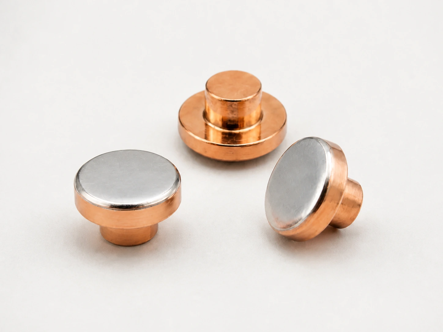
접점 구조와 적용 범위
솔리드 접점은 헤드와 샹크 전체가 하나의 접점재로 이루어집니다. 클래드·바이메탈 접점은 은계 접점재가 구리계 캐리어의 기능면에 금속학적으로 결합된 구조이며, 접점재 층의 두께는 전해도금 두께와 같은 개념이 아닙니다.
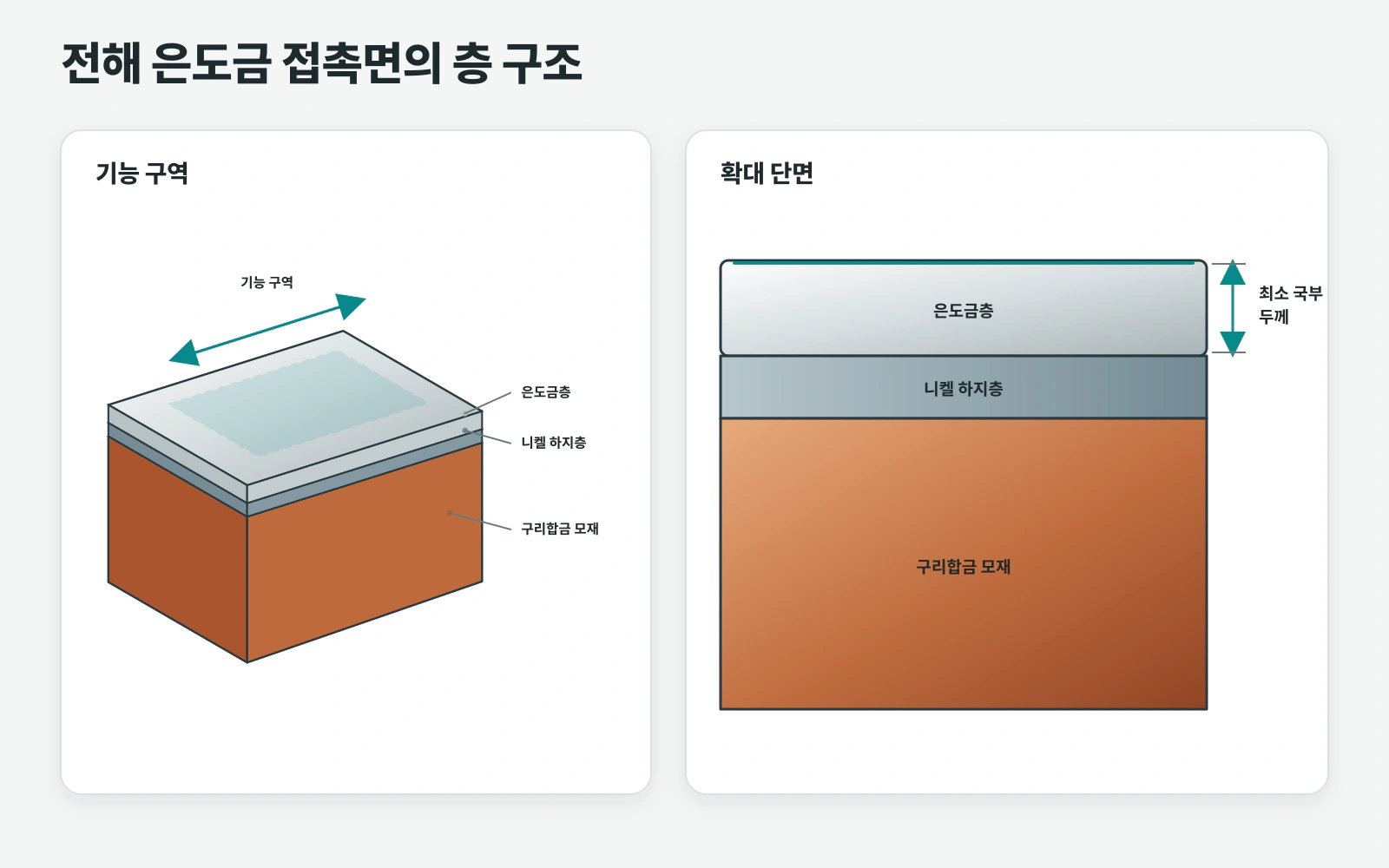
전해 은도금 접점은 구리 또는 구리합금 모재 표면에 마이크론 단위의 은 기능층을 형성합니다. 필요에 따라 니켈 등의 하지층을 적용할 수 있으며, 튜블러 접점은 샹크 내부에 공동이 있는 체결 형상을 뜻하므로 재료 구분과 형상 구분을 혼동하지 않아야 합니다.
반복 결합, 진동 노출, 고정 체결 및 미끄럼 접점은 마모·프레팅·발열을 중심으로 평가합니다. 회로를 개폐하면서 아크 침식과 용착이 발생하는 스위칭 접점은 합금 조성, 아크 에너지와 개폐 조건이 지배하므로 별도의 설계 체계가 필요합니다.

은도금 접점 두께와 유효 은 재고
은도금 접점 두께가 직접 늘리는 것은 제품 수명 자체가 아니라 정상 마모에 사용할 수 있는 은의 여유입니다. 실제 수명에 기여하는 값은 측정하기 쉬운 평탄부의 평균이 아니라 접촉 자국과 운동 트랙을 덮고 있는 기능영역의 최소 국부 두께입니다.
선도금 소재를 굽히거나 엠보싱하면 인장되는 외측과 돌출부에서 은층이 얇아질 수 있습니다. 후도금 공정도 돌출부, 오목부, 에지와 치구 접점의 전류밀도 차이로 두께 분포가 달라지므로, 성적서 한 지점의 값만으로 기능면 전체를 대표할 수 없습니다.
두께 증가와 수명 증가는 일반적으로 비례하지 않습니다. 접촉력이 변하거나 트랙이 선택도금 경계를 벗어나고, 마모분이 접촉영역에 축적되거나 계면 균열이 먼저 발생하면 은의 총량이 많아도 기능 수명은 짧아질 수 있습니다.
수명 종료 기준
적정 은도금 접점 두께는 먼저 고장 증거를 정의한 뒤 역으로 결정합니다. 목표 삽발 횟수 또는 이동 거리, 접촉하중, 미동 진폭과 주파수, 전류, 온도 및 분위기를 고정하고 어떤 전기·열·기계·표면 변화에서 사용을 종료할지 합의해야 합니다.
저레벨 신호 접점은 규정 조건에서 접촉저항이 지속적으로 한계를 넘거나 순간 저항 변동이 기능 오류를 일으키는 시점을 봅니다. 전력 접점은 접촉 전압강하, 안정화 온도상승과 접촉력 유지가 중요하며, 미끄럼 접점은 트랙의 은 연속성, 하지층 노출, 재료전이와 저항 불연속을 함께 판정합니다.
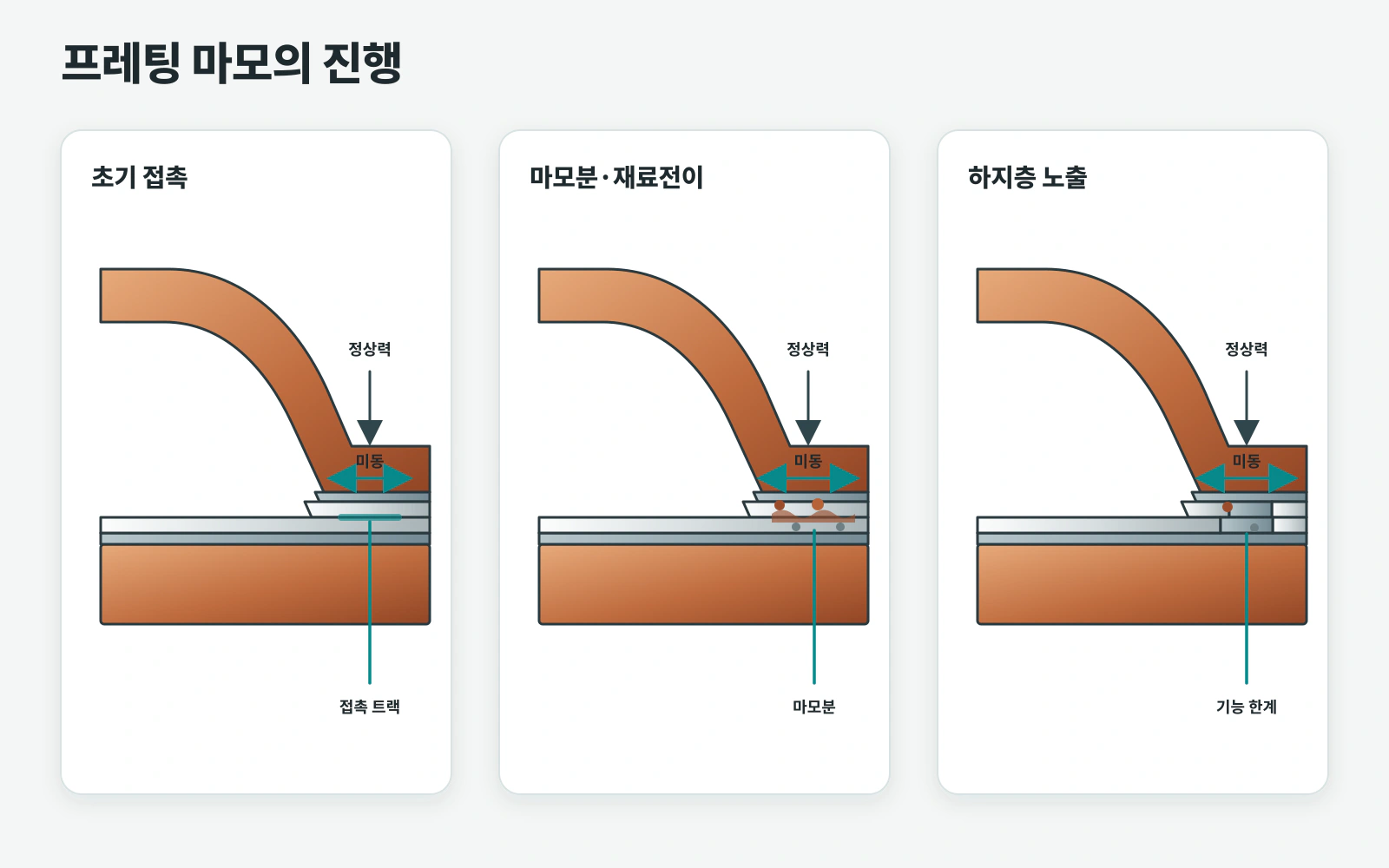
구리가 보이는 시점만을 수명 종료로 잡으면 실제 고장을 늦게 포착할 수 있습니다. 니켈 하지층 노출, 접촉력 저하 또는 마모분 재유입으로 전기 성능이 먼저 무너질 수 있으므로 평균 수명뿐 아니라 최초 고장, 시편 간 분포와 고장 형태를 함께 기록합니다.
| 사용 조건 | 주요 고장 경로 | 핵심 판정 증거 |
|---|---|---|
| 반복 결합 | 접착·연삭 마모, 트랙 이동 | 저항 추이, 삽발력, 잔존 은층 |
| 진동 체결 | 프레팅, 마모분 축적, 접촉력 저하 | 저항 스파이크, 미동량, 마모분 위치 |
| 정격전류 체결 | 전류 집중, 국부 발열, 응력 완화 | 전압강하, 온도상승, 접촉력 |
| 미끄럼 접촉 | 재료전이, 소성 유동, 트랙 확장 | 이동 중 저항, 마찰력, 트랙 단면 |
연질 은과 경질 은
연질 은은 실제 접촉점의 미세 형상에 순응하기 쉬워 낮은 초기 접촉저항 형성에 유리할 수 있습니다. 반면 높은 하중이나 긴 미끄럼 거리에서는 소성 유동, 접착 마모와 상대재로의 재료전이가 커질 수 있어 접촉 조건과 함께 평가해야 합니다.
경질 은은 석출 조직과 공석 성분을 조절해 내마모성을 높이는 방향으로 사용되지만 모든 조건에서 우수한 것은 아닙니다. 경도 상승과 함께 연성, 전도도, 잔류응력, 마찰 거동이 달라질 수 있으므로 동일한 두께라도 연질 은과 별도 사양으로 관리합니다.
매트·반광택·광택은 외관 명칭만으로 성능 등급을 대신할 수 없습니다. 도면과 발주서에는 은도금 유형, 필요한 순도 또는 성능 범위, 경도 시험 조건, 후처리와 윤활 유무를 명시해야 공정 간 결과를 비교할 수 있습니다.
도금층·하지층·모재
은층의 성능은 모재와 계면에서 분리되지 않습니다. 구리합금의 재질과 조질은 스프링 복원력과 접촉력 유지에 영향을 주고, 세정·활성화·스트라이크 등의 전처리는 초기 밀착력과 계면 결함을 좌우합니다.
니켈 하지층은 구리 확산 억제와 열노화 후 계면 안정화에 유리할 수 있으나 모든 구조의 필수 조건은 아닙니다. 굽힘부 균열, 노출 후 접촉저항 변화, 필요한 연성과 후속 공정을 검토해 직접 은도금 또는 다른 계면 설계와 비교해야 합니다.
도금 내부응력과 박리는 두께 하나로 설명할 수 없습니다. 욕 조성, 첨가제, 전류밀도, 온도, 교반, 석출 속도와 바탕면 상태가 함께 작용하므로 단면 관찰, 밀착력, 굽힘 및 열노화 후 계면 상태를 실제 공정 상·하한에서 확인합니다.
프레팅과 성형 조건
프레팅은 육안으로 구분하기 어려운 작은 상대 운동이 반복되면서 접촉면과 마모분이 재배치되는 현상입니다. 진폭이 작으면 마모분과 표면막이 접촉영역 안에 머물러 저항 변동을 키울 수 있고, 진폭이 커지면 배출은 쉬워져도 마모량과 트랙 폭이 증가할 수 있습니다.
접촉하중이 높으면 실제 접촉점이 넓어져 초기 저항은 낮아질 수 있으나 소성 유동, 접착과 재료전이가 커질 가능성도 있습니다. 하중이 너무 낮으면 진동 중 접촉점이 불안정해지므로 하중과 미동의 영향을 어느 한 방향으로 일반화해서는 안 됩니다.
프레스 성형은 기능면의 국부 두께와 접촉 위치를 동시에 바꿉니다. 굽힘 외측의 인장, 엠보싱부의 두께 변화, 공구흔과 버, 조립 공차에 따른 트랙 이동을 완성품과 실제 상대재 조합에서 확인해야 하며, 선택도금 경계는 최악 공차의 접촉 자국까지 포함해야 합니다.

접촉저항과 온도상승
저레벨 접촉저항은 4선식으로 측정해 리드선과 접속부 저항을 분리합니다. 측정 전류와 개방회로전압을 제한하여 시험 자체가 표면막을 전기적·열적으로 파괴하지 않도록 하고, 초기값뿐 아니라 반복 운동 중의 순간 변동과 시험 후 안정값을 같은 조건으로 비교합니다.
정격전류 온도상승은 별도의 부하 시험입니다. 주변 온도, 도체 길이와 단면, 체결 상태, 통풍, 측정점과 열 안정화 시간을 고정하지 않으면 접촉부가 아닌 시험 배선과 외부 접속의 영향이 결과에 섞입니다.
초기 저항이 낮아도 열노화나 반복 운동 후 접촉력이 줄면 온도상승이 급격히 커질 수 있습니다. 반대로 온도상승이 허용 범위여도 짧은 저항 스파이크가 신호 오류를 만들 수 있으므로 저레벨 전기 성능과 전력 발열 성능은 분리해 시험하고 동일 시편의 변화 이력으로 연결합니다.
황화·기공·윤활
은 표면은 황 성분이 있는 분위기에서 변색과 표면막을 형성하며, 그 영향은 접촉하중, 미끄럼 정도, 전류 수준과 생성물의 배출 여부에 따라 달라집니다. 두꺼운 은층은 모재 노출을 늦출 수 있지만 이미 형성된 기능면의 표면막을 제거하는 대책은 아닙니다.
기공과 국부 결함은 하지층 또는 모재로 이어지는 부식 경로가 될 수 있습니다. 위험도는 두께뿐 아니라 바탕면 청정도와 거칠기, 석출 조건, 하지층의 연속성, 형상 및 후속 성형에 좌우되므로 기능영역에 맞춘 시험 위치와 판정법이 필요합니다.
윤활은 마찰과 마모를 낮출 수 있지만 도포량, 점도, 이동성, 온도 안정성과 오염 포집 특성이 맞지 않으면 접촉저항 변동을 키울 수 있습니다. 무윤활과 윤활 후보는 실제 상대재와 온도·분위기에서 비교하고 세척, 보관과 장기 사용 후의 변화를 포함해 선정합니다.
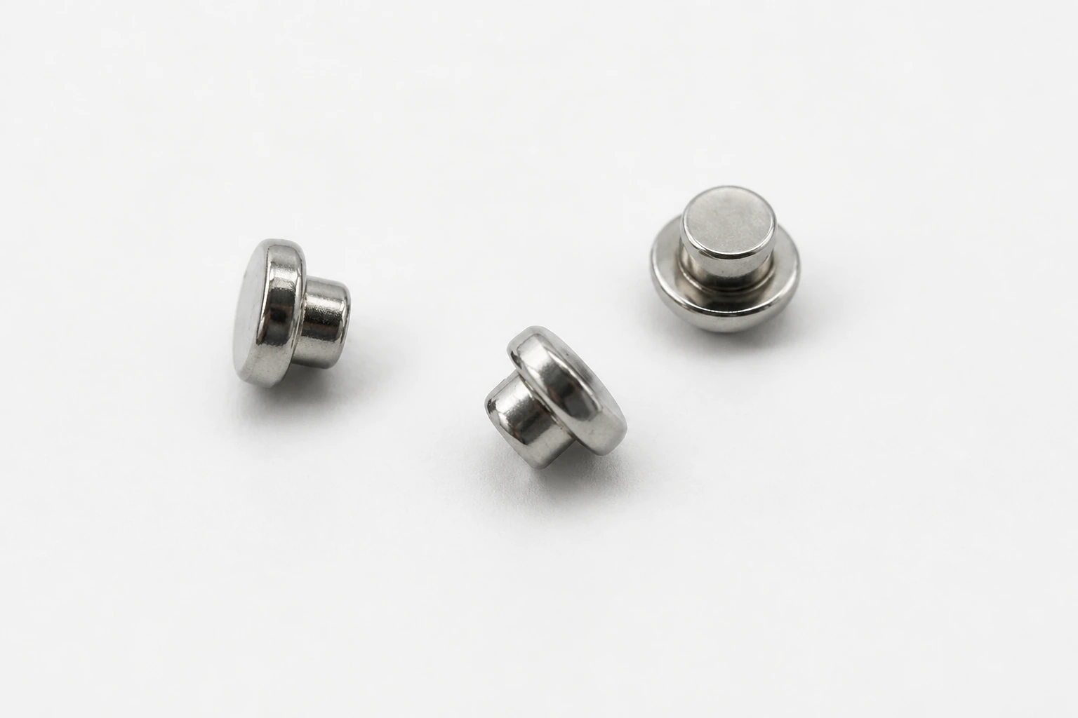
도면 사양과 두께 측정
은도금 접점 두께를 규정하는 도면에는 모재 합금과 조질, 선도금·후도금 구분, 은도금 유형, 하지층, 기능영역과 제외영역을 함께 표시합니다. 핵심 관리값은 접촉 트랙을 포함하는 구역의 최소 국부 두께이며, 측정점·측정면·시편 수·측정법과 합격 기준까지 한 묶음으로 지정합니다.
XRF는 비파괴 양산 관리에 적합하지만 측정 면적, 초점, 곡률, 에지, 다층 구조와 교정 표준의 영향을 받습니다. X선 신호로 얻은 면적당 질량을 두께로 환산할 때 적용한 재료 밀도와 형상 보정도 고정해야 위치별 결과를 비교할 수 있습니다.
단면 측정은 층 구조와 국부 두께를 직접 확인하는 데 유용하지만 절단 위치, 마운팅, 연마와 관찰 방향에 따라 결과가 달라질 수 있습니다. 초도품에서 XRF와 단면값의 위치별 상관성을 만든 뒤, 양산에서는 동일한 치구·교정·측정 위치로 측정시스템 적합성과 공정능력을 관리합니다.
| 관리 항목 | 도면·발주 요구 | 초도 및 양산 증거 |
|---|---|---|
| 재료·성형 | 합금, 조질, 소재 두께, 공정 순서 | 치수, 버, 접촉력, 굽힘부 상태 |
| 도금 시스템 | 은 유형, 하지층, 후처리, 기능영역 | 순도·경도, 밀착력, 열노화 단면 |
| 두께 관리 | 최소 국부값, 측정 위치와 방법 | XRF-단면 상관성, 최소값과 분포 |
| 사용 조건 | 상대재, 하중, 운동, 전류, 환경 | 실제 조합의 저항·온도·마모 이력 |
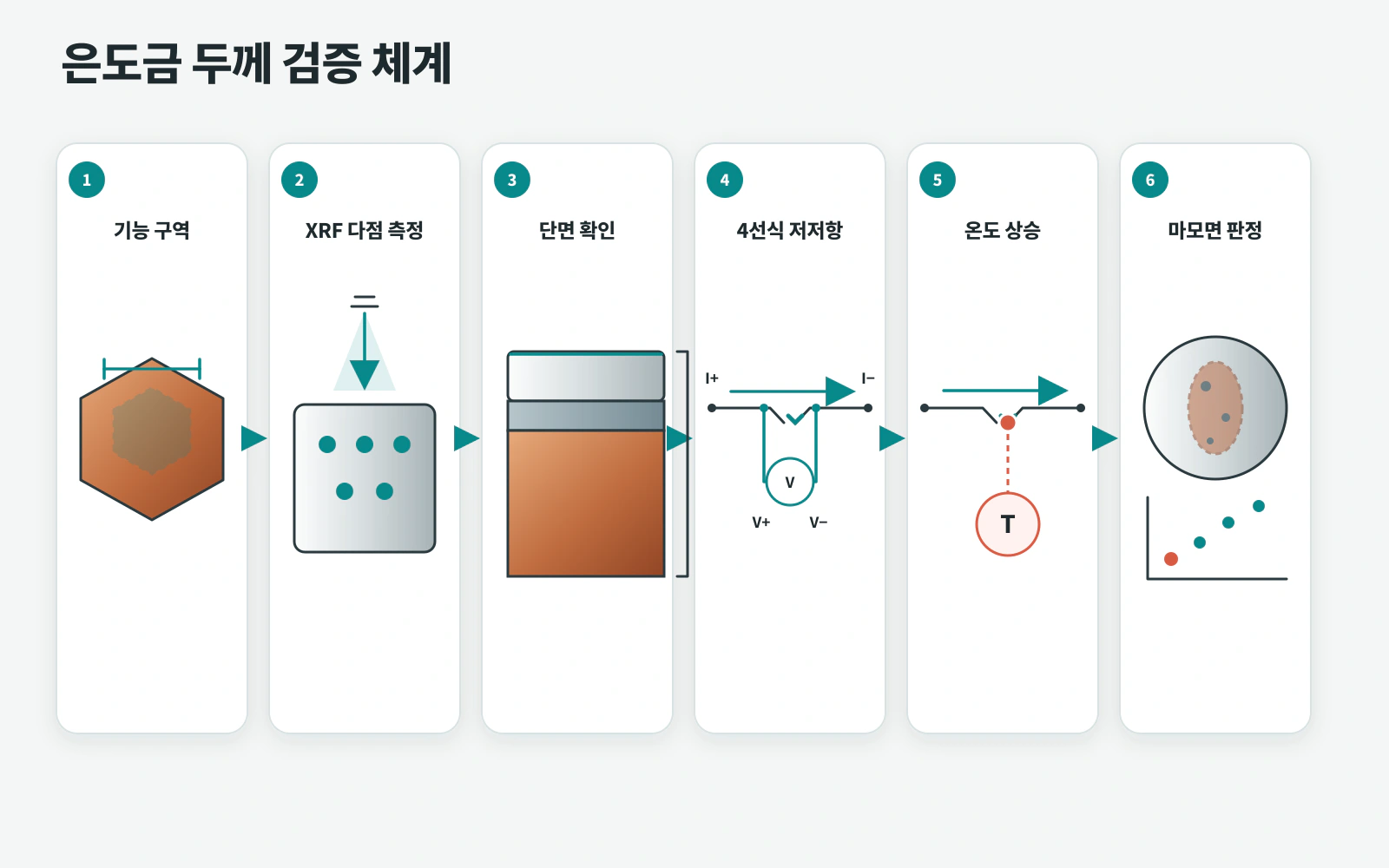
후보 사양과 양산 검증
후보 두께를 비교할 때는 모재 로트, 성형 조건, 접촉 형상과 상대재를 동일하게 유지합니다. 두께와 동시에 은 유형, 하지층 또는 접촉하중을 바꾸면 수명 차이의 원인을 분리할 수 없으므로 변경 변수와 고정 변수를 시험계획에 명확히 기록합니다.
검증은 초기 치수·접촉력·두께 분포와 계면 상태를 확인한 뒤 실제 삽발·프레팅·미끄럼 조건을 적용하는 순서로 구성합니다. 사용 환경에 따라 열노화, 습도 또는 부식성 분위기를 추가하고, 저레벨 접촉저항과 정격전류 온도상승은 목적별 조건으로 나누어 평가합니다.
판정은 평균값보다 최초 고장, 시편 간 분포, 위치별 잔존 은층과 고장 형태를 중시합니다. 은이 남아 있어도 저항 불안정이나 접촉력 저하가 기준을 넘으면 기능 수명은 종료된 것이며, 외관 변화만으로 전기적 고장을 단정하지도 않습니다.
최종 은도금 접점 두께 사양은 단일 두께값이 아니라 기능영역의 최소값, 허용 공정범위, 측정 체계, 수명시험과 변경관리 조건이 결합된 문서로 남아야 합니다. 이 체계가 갖춰져야 설계 요구, 구매 성적서와 양산 품질 데이터가 같은 기준으로 연결됩니다.
English Technical Overview
Silver-plated contact thickness is not merely a micron value. It is a design variable that connects the amount of silver secured in the functional zone with the defined end-of-life condition. Even at the same thickness, differences in contact force, micromotion amplitude, deposit structure, underlayer, forming history, mating material, and service environment can produce entirely different wear rates and contact-resistance behavior.
The drawing should specify the minimum local thickness in the actual contact track rather than an average over the entire component. For both initial qualification and production, XRF measurements, cross-sectional observation, four-wire low-level contact resistance, rated-current temperature rise, and the wear surface after repeated motion should be connected in one validation system. This is how the design value and production quality can be kept consistent.
Contact Structures and Application Scope
A solid contact is made of one contact material throughout the head and shank. In a clad or bimetal contact, a silver-based contact material is metallurgically bonded to the functional face of a copper-based carrier. The thickness of that structural contact-material layer is not the same concept as electrolytic plating thickness.
An electroplated silver contact has a micron-scale functional silver layer deposited on a copper or copper-alloy substrate. An underlayer such as nickel may be used when required. A tubular contact, meanwhile, refers to a fastening geometry with a hollow shank; material classification and geometry classification must therefore not be confused.
Repeatedly mated, vibration-exposed, fixed mated, and sliding contacts are evaluated primarily for wear, fretting, and heating. Switching contacts that make and break a circuit are dominated by arc erosion and welding. Their alloy composition, arc energy, and switching conditions require a separate design framework.
Silver-Plated Contact Thickness and Effective Silver Inventory
What silver-plated contact thickness directly increases is not product life itself, but the reserve of silver available for normal wear. The value that contributes to actual life is not the average on an easy-to-measure flat surface. It is the minimum local thickness in the functional zone covering the contact scar and motion track.
When pre-plated material is bent or embossed, the silver layer may become thinner on stretched outer surfaces and raised features. Post-plating also develops a thickness distribution because current density differs at projections, recesses, edges, and rack-contact locations. A result from one point on a certificate cannot represent the entire functional surface.
An increase in thickness does not generally produce a proportional increase in life. Even with a larger total amount of silver, functional life can remain short if contact force changes, the track moves outside the selective-plating boundary, debris accumulates in the contact region, or interfacial cracking occurs first.
End-of-Life Criteria
The appropriate silver-plated contact thickness is determined by defining failure evidence first and then working backward. The target mating-cycle count or travel distance, contact force, micromotion amplitude and frequency, current, temperature, and atmosphere must be fixed. The electrical, thermal, mechanical, or surface change that ends service must then be agreed upon.
For low-level signal contacts, the critical point is when contact resistance persistently exceeds the limit under specified conditions or when transient resistance fluctuations cause a functional error. For power contacts, contact voltage drop, stabilized temperature rise, and retention of contact force are important. For sliding contacts, continuity of silver in the track, underlayer exposure, material transfer, and resistance discontinuity are evaluated together.
Using visible copper as the only end-of-life point can identify failure too late. Electrical performance may already have collapsed because of nickel-underlayer exposure, contact-force loss, or the re-entry of wear debris. The record should therefore include first failure, specimen-to-specimen distribution, and failure mode, not only average life.
| Service condition | Primary failure path | Key evaluation evidence |
|---|---|---|
| Repeated mating | Adhesive and abrasive wear, track migration | Resistance trend, mating force, remaining silver |
| Vibration in the mated state | Fretting, debris accumulation, contact-force loss | Resistance spikes, micromotion, debris location |
| Rated-current connection | Current constriction, local heating, stress relaxation | Voltage drop, temperature rise, contact force |
| Sliding contact | Material transfer, plastic flow, track expansion | Resistance during motion, friction force, track cross-section |
Soft Silver and Hard Silver
Soft silver can conform readily to the microgeometry of the real contact spots, which can support low initial contact resistance. Under high load or over a long sliding distance, however, plastic flow, adhesive wear, and material transfer to the mating surface can increase. It must therefore be evaluated with the intended contact conditions.
Hard silver is used to improve wear resistance by controlling the deposit structure and co-deposited constituents, but it is not superior under every condition. Increasing hardness can also change ductility, conductivity, residual stress, and friction behavior. Soft and hard silver must therefore be managed as separate specifications even when their thickness is identical.
Matte, semi-bright, and bright are not appearance labels that can substitute for a performance grade. The drawing and purchase specification should define the silver-deposit type, required purity or performance range, hardness-test conditions, post-treatment, and lubrication status so that results from different processes can be compared.
Plating Layer, Underlayer, and Substrate
The performance of the silver layer cannot be separated from its substrate and interface. The material and temper of the copper alloy influence spring recovery and retention of contact force. Preparation processes such as cleaning, activation, and strike deposition determine initial adhesion and interfacial defects.
A nickel underlayer can help suppress copper diffusion and stabilize the interface after thermal aging, but it is not mandatory for every structure. Bend cracking, the change in contact resistance after exposure, required ductility, and downstream processing must be reviewed when comparing it with direct silver plating or another interface design.
Deposit stress and delamination cannot be explained by thickness alone. Bath chemistry, additives, current density, temperature, agitation, deposition rate, and base-surface condition act together. Cross-sectional appearance, adhesion, bend performance, and interfacial condition after thermal aging should therefore be checked at the upper and lower limits of the actual process window.
Fretting and Forming Conditions
Fretting is the repeated redistribution of the contact surface and wear debris by relative motion that can be difficult to distinguish visually. At small amplitudes, debris and surface films can remain in the contact region and increase resistance fluctuation. At larger amplitudes, debris may be cleared more readily, but wear volume and track width can increase.
Higher contact force can enlarge the real contact area and reduce initial resistance, but it can also increase plastic flow, adhesion, and material transfer. If the force is too low, contact spots can become unstable during vibration. The effects of force and micromotion must not be generalized as acting beneficially in only one direction.
Press forming changes both the local thickness of the functional surface and the contact location. Tensile strain on the outer bend, thickness change at embossed features, tool marks and burrs, and track migration caused by assembly tolerance should be checked with the finished component and actual mating part. The selective-plating boundary must cover the contact scar under the worst tolerance condition.
Contact Resistance and Temperature Rise
Low-level contact resistance is measured with a four-wire arrangement to separate lead and connection resistance. Measurement current and open-circuit voltage are limited so that the test itself does not electrically or thermally disrupt the surface film. The initial value, transient fluctuations during repeated motion, and stable post-test value should all be compared under the same conditions.
Rated-current temperature rise is a separate load test. Unless ambient temperature, conductor length and cross-section, fastening condition, airflow, measurement point, and thermal-stabilization time are fixed, the result will include effects from the test wiring and external connections rather than the contact alone.
Initial resistance can be low while temperature rise increases sharply after thermal aging or repeated motion reduces contact force. Conversely, brief resistance spikes can cause signal errors even when temperature rise remains acceptable. Low-level electrical performance and power-heating performance should be tested separately and then connected through the history of the same specimens.
Sulfidation, Porosity, and Lubrication
In a sulfur-bearing atmosphere, a silver surface develops discoloration and surface films. Their effect depends on contact force, the degree of sliding, current level, and whether the reaction products are removed from the contact region. A thicker silver layer can delay substrate exposure, but it is not a remedy for a film that has already formed on the functional surface.
Pores and local defects can create a corrosion path to the underlayer or substrate. The risk is governed not only by thickness but also by base-surface cleanliness and roughness, deposition conditions, underlayer continuity, geometry, and subsequent forming. Test locations and acceptance methods must match the functional zone.
Lubrication can reduce friction and wear, but an unsuitable application amount, viscosity, mobility, temperature stability, or contamination-capture behavior can increase contact-resistance fluctuation. Lubricated and unlubricated candidates should be compared with the actual mating material and service temperature and atmosphere, including changes after cleaning, storage, and long-term use.
Drawing Specifications and Thickness Measurement
A drawing that specifies silver-plated contact thickness should identify the substrate alloy and temper, pre-plating or post-plating sequence, silver-deposit type, underlayer, functional zone, and excluded zones. The essential control value is the minimum local thickness in the zone containing the contact track. Measurement points, measurement surface, specimen count, method, and acceptance criterion should be specified as one set.
XRF is suitable for nondestructive production control, but it is affected by measurement area, focal geometry, curvature, edges, multilayer construction, and calibration standards. When X-ray signal expressed as mass per unit area is converted to thickness, the material density and geometry correction used in the conversion must also be fixed for location-to-location comparison.
Cross-sectional measurement is useful for directly examining the layer structure and local thickness, but the result can vary with section location, mounting, polishing, and viewing direction. A location-specific correlation between XRF and cross-sectional values should be established during initial qualification. Production control should then use the same fixture, calibration, and measurement locations to manage measurement-system suitability and process capability.
| Control item | Drawing and purchasing requirement | Initial and production evidence |
|---|---|---|
| Material and forming | Alloy, temper, stock thickness, process sequence | Dimensions, burrs, contact force, bend condition |
| Plating system | Silver type, underlayer, post-treatment, functional zone | Purity or hardness, adhesion, cross-section after thermal aging |
| Thickness control | Minimum local value, measurement location and method | XRF-to-cross-section correlation, minimum value and distribution |
| Service conditions | Mating material, force, motion, current, environment | Resistance, temperature, and wear history of the actual pair |
Candidate Specifications and Production Validation
When candidate thicknesses are compared, the substrate lot, forming conditions, contact geometry, and mating material should be held constant. If silver type, underlayer, or contact force is changed at the same time as thickness, the cause of a life difference cannot be isolated. Changed and fixed variables must be recorded clearly in the test plan.
Validation begins with initial dimensions, contact force, thickness distribution, and interfacial condition, followed by the actual mating, fretting, or sliding conditions. Thermal aging, humidity, or a corrosive atmosphere can be added as required by the service environment. Low-level contact resistance and rated-current temperature rise are evaluated under separate conditions suited to their purposes.
The evaluation should emphasize first failure, specimen-to-specimen distribution, location-specific remaining silver, and failure mode rather than only averages. Functional life is over if resistance instability or contact-force loss exceeds the limit even while silver remains. An appearance change alone should not be taken as proof of electrical failure.
The final silver-plated contact thickness specification should not be a single thickness value. It should combine the minimum value in the functional zone, allowable process range, measurement system, life test, and change-control conditions. With this structure, design requirements, purchasing certificates, and production quality data can be connected by the same criteria.
추가 정보
검색엔진용 요약
은도금 접점 두께는 부품 전체의 평균값보다 실제 접촉 트랙의 최소 국부값으로 관리해야 합니다. 기능영역과 수명 종료 기준을 먼저 정하고, XRF·단면 측정을 접촉저항, 온도상승, 프레팅 및 마모 결과와 연결해 후보 사양과 양산 공정범위를 검증합니다.
핵심 포인트
- 전해 은도금의 마이크론 두께는 솔리드·클래드 접점의 구조 재료층 두께와 다른 개념입니다.
- 수명에 직접 기여하는 값은 접촉 자국과 운동 트랙을 덮는 기능영역의 최소 국부 두께입니다.
- 두께 증가는 정상 마모용 은의 여유를 늘리지만 접촉력 저하, 계면 균열과 표면막 고장을 해결하지는 못합니다.
- 연질 은과 경질 은은 경도뿐 아니라 연성, 전도도, 잔류응력과 재료전이를 포함해 별도 사양으로 관리합니다.
- XRF 양산값은 초도 단면값과 위치별 상관성을 확보하고 동일한 치구·교정·측정점으로 관리합니다.
- 합격 판정은 평균 수명보다 최초 고장, 시편 간 분포, 접촉저항, 온도상승과 마모 형태를 함께 봅니다.
FAQ
모든 은도금 접점에 공통으로 적용할 권장 두께가 있습니까?
공통 단일값은 없습니다. 접촉하중, 운동, 상대재, 전류, 환경과 목표 수명을 정한 뒤 기능영역의 최소 국부 두께를 실제 수명시험 결과와 연결해야 합니다.
클래드 접점의 은층과 전해 은도금은 같은 구조입니까?
같은 구조가 아닙니다. 클래드는 접점재와 캐리어를 금속학적으로 결합한 구조 재료이고, 전해 은도금은 모재 표면에 석출한 마이크론 단위 기능층입니다.
구리가 보이지 않으면 계속 사용할 수 있습니까?
반드시 그렇지는 않습니다. 하지층 노출, 접촉력 저하, 저항 불안정이나 과도한 온도상승이 기준을 넘으면 은이 일부 남아 있어도 기능 수명은 끝납니다.
경질 은이 연질 은보다 항상 오래갑니까?
항상 그렇지는 않습니다. 상대재, 접촉하중, 이동 거리, 윤활과 환경에 따라 지배 고장이 달라지므로 실제 조합에서 경도·마모·전도 성능을 비교해야 합니다.
성형품의 두께는 어디에서 측정해야 합니까?
실제 접촉 트랙과 최악 조립 공차가 포함되는 기능영역을 지정해야 합니다. 접촉 돌기, 굽힘 외측과 선택도금 경계처럼 국부 박화 가능성이 큰 위치를 우선 확인합니다.
XRF 측정만으로 양산 두께를 판정할 수 있습니까?
초도 단계에서 동일 위치의 단면 측정과 상관성을 확보한 뒤 사용할 수 있습니다. 곡률, 에지, 측정 면적, 교정 표준과 형상 보정을 고정해야 로트 간 비교가 가능합니다.
관련 주제
기능영역과 최소 국부값
접촉 자국의 위치와 공차를 기준으로 도금 구역을 정하고, 평균값이 아닌 최취약 위치의 최소값을 도면과 성적서에 연결합니다.
XRF와 단면 측정의 상관성
비파괴 양산 측정은 단면으로 확인한 층 구조와 위치별 상관성을 확보해야 하며, 치구와 교정 조건의 변경도 관리 대상입니다.
전기·열·마모의 통합 판정
저레벨 접촉저항, 정격전류 온도상승과 반복 운동 후 마모면을 동일 시편의 이력으로 연결하면 고장 원인과 공정 산포를 구분할 수 있습니다.
내부 링크
관련 키워드
은도금 접점 두께, 전기접점, 기능영역, 최소 국부 두께, 유효 은 재고, 연질 은, 경질 은, 니켈 하지층, 프레팅 마모, 저레벨 접촉저항, XRF 측정, 단면 측정