전기 접점 신뢰성 - 검사 장비 체계
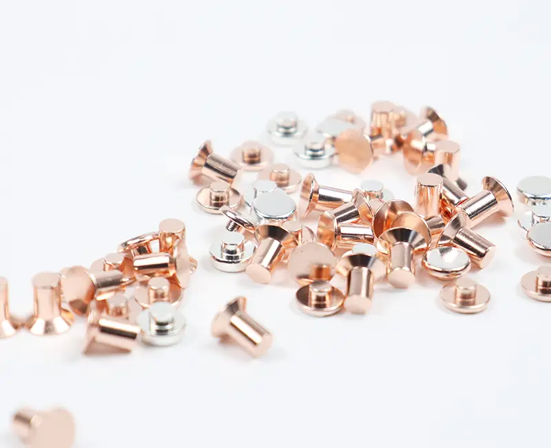
전기접점 (Electrical Contacts) 신뢰성
전기 접점은 “도금/표면상태–미세형상–재료조성–접촉저항”이 연쇄적으로 연결되는 부품입니다. 생산 직후 외관이 양호해 보이더라도, 사용 환경에서의 신뢰성 저하는 미세한 치수 편차, 도금 두께 편차, 기지재와 도금층의 조성 변화, 표면 경도(또는 변형층) 변화, 단면 결함(공극·박리·균열)에서 시작되는 경우가 많습니다. 따라서 신뢰성 검사는 장비를 나열하는 방식이 아니라, “어떤 품질특성(CTQ)을 어떤 원리로 검증하고, 결과가 공정에 어떤 피드백을 주는가”로 설계되어야 합니다.
신뢰성 검사에서 관리해야 할 핵심 품질특성(CTQ)
전기 접점의 신뢰성은 아래 특성들이 동시에 만족될 때 확보됩니다.
전기적 특성
기준 온도(일반적으로 20 °C)에서의 접촉저항/부품 저항 안정성
반복 접촉 후 저항 상승(마모·산화·미세박리) 억제
도금층/기지재 조성 변화에 따른 저항 편차 최소화
기계·재료 특성
표면/근표면 경도(가공경화, 열영향, 도금 경도 포함)
도금층 두께 및 다층 구조(예: Ni barrier + Ag 또는 Sn) 균일성
단면 결함(공극, 기공, 박리, 크랙, 오염층) 부재 또는 허용범위 관리
형상·치수 특성
접촉부의 실제 접촉면적을 결정하는 미세 치수/형상(평면도, 원통도, 모서리 R, 버urr, 변형량)
조립품/상대부품과의 간섭 및 접촉압 분포에 영향을 주는 3차원 형상 정확도
검사 흐름 설계
출하 검사(Release): 빠르고 재현성 있는 비파괴 중심(치수, XRF 두께/성분, 저항)으로 로트 합격/불합격을 판정합니다.
공정감시(Process): 공정 변동을 조기에 잡기 위해 핵심 항목을 짧은 주기로 샘플링합니다(도금 두께, 저항, 핵심 치수).
심층분석(FA): 이상 로트 또는 고객 클레임 시 파괴/단면 분석(마운팅–절단–연마–현미경)과 경도/형상 상관을 확인합니다.
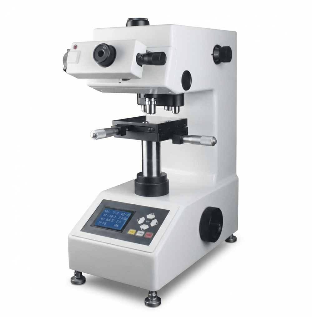
HV 경도 측정기 – 표면 경도와 전기적 안정성
HV(비커스) 경도는 단순히 “단단함”을 보는 항목이 아닙니다. 전기 접점에서는 다음과 같은 품질 리스크를 조기에 드러냅니다.
가공경화/열영향: 프레스·절삭·연마·버 제거 공정에서 접촉부 근표면의 변형층이 커지면, 접촉 시 미세 파편이 발생하거나 표면 산화/오염층이 쉽게 정착되어 저항이 상승할 수 있습니다.
도금층 특성 변화: Ag, Sn 계열 도금은 공정 조건에 따라 결정립, 내부응력, 경도/연성이 달라집니다. 경도가 과도하게 높아지면 균열·박리 민감도가 증가할 수 있고, 너무 낮으면 마모로 두께 손실이 빨라질 수 있습니다.
측정 신뢰도: 도금층이 얇을수록(수 µm 수준) 기지재 영향이 커져 “측정 하중/압흔 크기”에 따라 값이 흔들립니다. 따라서 하중 선정, 표면 거칠기, 측정 위치(접촉부/비접촉부)를 고정해야 합니다.
“표면 경도 절대값”보다도, 로트 간 분산과 위치별 편차(접촉부 vs 비접촉부, 중앙 vs 모서리)입니다.
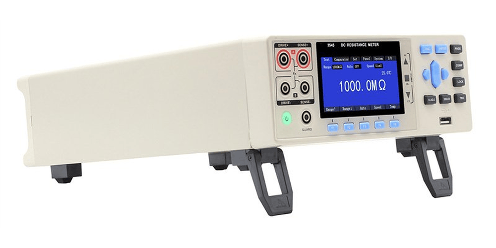
저항 측정 (기준 온도 저항값)
전기 접점의 저항 평가는 대개 마이크로옴(µΩ)~밀리옴(mΩ) 영역까지 내려갑니다. 이때 측정 리스크는 “접점 자체 저항”보다 “리드선·클램프·측정 접촉부”에서 더 크게 나타납니다.
-
4선식(켈빈) 구성: 전류 인가선(2선)과 전압 검출선(2선)을 분리하여, 리드/클램프 접촉저항 영향을 최소화합니다.
-
기준 온도 보정: 현장 온도가 20 °C에서 벗어나면 저항은 온도계수에 따라 변합니다. 측정 시점 온도와 기준 온도 간 보정식을 내부 규격으로 고정하면 로트 비교가 일관됩니다.
-
지그 반복성: 클램핑 압력, 접촉 위치, 산화막 제거 여부(예: 프리-스크럽), 측정 전 안정화 시간(전류 인가 후 몇 초)을 고정하지 않으면 데이터가 “공정 품질”이 아니라 “측정 산포”가 됩니다.
저항 데이터는 단독으로 쓰기보다, XRF 두께/조성 및 치수 데이터와 함께 해석할 때 원인 추적성이 크게 올라갑니다. 예를 들어 저항이 높아졌을 때, 두께 저하인지(도금 부족), 조성 변화인지(합금·불순물), 접촉부 형상 변화인지(실접촉면적 감소)를 분리할 수 있습니다.
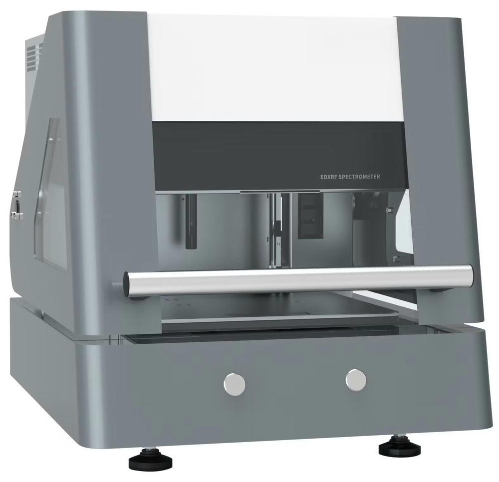
ED-XRF 성분분석 RoHS 스크리닝 도금 두께
ED-XRF는 전기 접점에서 “가장 비용 대비 효과가 큰 비파괴 분석 장비” 중 하나입니다.
도금 두께(단층/다층)
Ni barrier, Ag, Sn 등 다층 구조를 운용하는 경우, 층별 두께 균일성이 접촉저항과 내식성에 직접 연결됩니다.
XRF 두께는 측정 스폿 크기와 표면 곡률, 기지재 조성, 다층 구조 모델링에 영향을 받으므로 제품별로 교정(표준시편 또는 단면 확인) 체계를 가져야 합니다.
성분분석(합금/기지재/도금 조성)
Ag 계열 접점에서 미량 원소 변화는 경도·산화거동·전기적 안정성에 영향을 줄 수 있습니다.
기지재(예: Cu계) 위 도금에서 확산/오염이 발생하면, 표면층 조성이 변하고 장기적으로 저항이 상승하는 경향이 나타날 수 있습니다.
RoHS 스크리닝
Pb, Cd, Hg, Cr(VI) 등 제한물질에 대한 스크리닝은 공급망 관리와 직결됩니다. XRF는 정밀 정량분석 장비가 아니라도, “로트 차단(스크리닝)” 관점에서는 강력합니다.
다만 RoHS의 공식 적합성은 재료선언/시험성적서 체계와 결합되어야 하며, XRF는 현장 검증 데이터를 제공하는 역할로 정의하는 것이 안정적입니다.
핵심은 XRF를 “측정기”가 아니라 “공정의 조성/두께 변동 감시 센서”로 운영하는 것입니다. 교정–검증–추적성(시편, 조건, 운영자, 로트)을 갖추면, 제품의 신뢰도는 크게 향상 됩니다.

접촉/비접촉 3차원 측정기 (CMM/광학)
전기 접점의 치수는 단순 길이/폭만의 문제가 아닙니다. 접촉 압력 분포, 편심, 상대부품 간 정렬오차가 접촉저항과 마모를 결정하므로, 3차원 형상(평면도·직각도·원통도·R·버)을 GPS 관점으로 관리해야 합니다.
접촉식 3차원(CMM)은 형상/치수의 추적성과 표준화에 유리합니다.
비접촉식(광학/레이저 등)은 연성 소재나 미세부품에서 변형 없이 빠르게 측정할 수 있습니다.
다만 “0.1 µm”라는 분해능(또는 표기 사양)은 측정 환경과 운용 조건이 따라주지 않으면 의미가 퇴색합니다. 안정적인 운영을 위해서는 다음이 필수입니다.
온도 관리(장비실/워크 온도)와 열평형 시간
측정 프로그램 고정(프로빙 경로, 속도, 필터)
게이지 R&R을 통한 측정 시스템 검증
기준 게이지/마스터를 이용한 주기적 검증(재검증)
이 체계가 잡히면, 치수 데이터는 단순 합격판정이 아니라 “금형·가공 조건의 미세 드리프트를 조기에 잡는 공정감시 지표”로 기능합니다.
비디오 메타 (비전 측정)
비전 기반 측정은 전기 접점처럼 “작고 빠르게 많이 만드는” 부품에서 현실적인 장점이 큽니다.
빠른 셋업과 높은 처리량
모서리, 슬롯, 펀칭 형상, 미세 R 등 2D 특징치의 반복 측정
현장 작업자의 운용 편의성
그러나 비전 측정은 조명, 초점, 에지 검출 알고리즘, 표면 반사(도금 광택)에 민감합니다. 따라서 제품별로 조명 조건(링/동축/백라이트), 임계값, 측정 기준선 정의를 문서화해야 하며, 주기적으로 “같은 부품을 같은 조건으로 재측정했을 때 데이터가 얼마나 흔들리는지”를 확인해야 합니다.
투영기
투영기는 정밀 측정 장비이면서 동시에 “형상 이상을 즉시 발견하는 검사 장비”입니다. 다음 상황에서 특히 효율적입니다.
형상의 윤곽 비교(마스터 도면 대비)
버, 찢김, 치핑, 변형 등 육안으로 놓치기 쉬운 결함의 확대 확인
신규 금형/셋업 변경 후 초기 품질 확인(First Article)
투영기의 장점은 “작업자 교육이 상대적으로 쉽고, 이상 판단이 빠르다”는 것입니다. 즉, 정밀 수치보다도 형상 이상을 빠르게 걸러내는 방어벽으로 두는 설계가 적합합니다.

| 검사 항목(CTQ) | 권장 측정 접근(표준/관행) | 대표 측정 조건 예시(현장 기준) | 주요 오차/변동 요인 | 공정 피드백 포인트 |
|---|---|---|---|---|
| 표면/근표면 경도(HV) | 비커스 경도 시험(금속 재료 경도 시험 체계 기반) | 제품/도금 두께에 맞춘 하중 선정, 동일 위치 반복 측정, 표면 조도 관리 | 도금층 얇을 때 기지재 영향, 표면 거칠기·곡률, 측정자 위치 편차 | 가공경화 과다(프레스/연마/버 제거), 열영향, 도금 조건 변화(결정립/내부응력) 점검 |
| 기준 온도 저항(µΩ~mΩ) | 4선식(켈빈) 저항 측정, 기준 온도 보정 운용 | 전류 인가/전압 검출 분리, 클램프 위치 고정, 온도 기록 후 20 °C 환산 규칙 적용 | 리드/클램프 접촉저항, 접촉면 산화막, 클램핑 압력·위치 변화, 온도 변동 | 도금 두께·조성 변동, 접촉부 형상/버, 표면 오염(세정/건조/포장) 개선 |
| 도금 두께/조성/유해물질(ED-XRF) | XRF 두께(단층/다층) + 합금/원소 스크리닝 + RoHS 스크리닝 | 제품별 스폿/측정 위치 정의, 표준시편/단면으로 주기 검증, 층 구조 모델 고정 | 스폿 크기 대비 형상 영향, 곡률/거칠기, 다층 모델링 오차, 기지재 조성 변화 | 도금 전처리/활성화, 전류밀도·시간, 욕 관리(금속 이온·첨가제), Ni barrier 유무 점검 |
| 3차원 치수/형상(CMM/비접촉) | CMM 성능 검증 체계 기반 + 측정 프로그램 표준화 | 온도 안정화, 동일 프로빙/스캔 조건, 마스터로 재검증, R&R 수행 | 온도·열팽창, 프로브/렌즈 상태, 조명·에지 검출, 고정 지그 변형 | 금형 마모/간극, 공구 마모, 성형 조건, 변형/스프링백 관리 |
| 비전(비디오 메타)/투영기 형상 확인 | 2D 특징치 반복 측정 + 윤곽 비교 | 조명/초점/임계값 표준화, 마스터 윤곽 기준, 초기품·변경점 집중 확인 | 반사(도금 광택), 조명 변화, 에지 검출 설정, 작업자 판단 편차 | 버/찢김/치핑/변형 발생 공정(프레스, 트리밍, 디버링) 즉시 점검 |
| 단면(마운팅-절단-연마-현미경) | 금속조직/단면 두께·계면 결함 평가(파괴 분석) | 절단 열손상 최소화, 연마 단계 표준화, x100 이상에서 계면/기공/박리 확인 | 절단/연마로 인한 인위적 결함, 연마 과다로 경계 흐림, 관찰 위치 편차 | XRF 교정 검증, 도금 박리/기공 원인(전처리·오염·응력) 규명, 공정 조건 재설계 |
전기 접점 신뢰성의 판단 기준
전기 접점의 신뢰성은 단일 검사 결과로 판단할 수 있는 항목이 아닙니다. 실제 신뢰성은 여러 품질 특성이 동시에 안정적으로 유지되고 있는지, 그리고 그 상태가 시간에 따라 반복되는지에 의해 결정됩니다. 중요한 것은 한 번의 합격 여부가 아니라 변화의 방향과 일관성입니다.
접촉 저항, 표면 상태, 형상 정밀도, 재료 특성은 서로 영향을 주는 관계에 있으며, 어느 한 요소의 미세한 변화는 일정 시간이 지난 뒤 성능 저하로 나타나는 경우가 많습니다. 따라서 신뢰성 관리는 개별 수치를 확인하는 방식이 아니라, 품질 지표들의 흐름과 상관관계를 관리하는 구조로 접근해야 합니다.
문제가 발생한 뒤 원인을 추적하는 단계가 아니라, 변화의 징후를 조기에 감지하고 공정 조건을 조정할 수 있는 상태를 의미합니다. 이러한 관리가 반복되면 품질은 특정 검사 시점의 결과가 아니라, 일상적인 생산 과정 속에서 안정적으로 유지되는 특성이 됩니다. 결국 전기 접점의 신뢰성은 별도로 강조해야 하는 성능이 아니라, 정상적인 생산이 지속될 때 자연스럽게 확인되는 결과로 나타납니다.
Electrical Contact Reliability – Inspection Equipment Framework
Overview of Electrical Contact Reliability
Electrical contacts are components in which plating condition, surface integrity, micro-geometry, material composition, and contact resistance are tightly coupled. Even when external appearance is acceptable immediately after production, reliability degradation in service environments often originates from subtle dimensional deviations, plating thickness variation, compositional changes between substrate and coating layers, surface hardness variation, or internal defects such as porosity, delamination, or micro-cracking.
For this reason, reliability inspection should not be organized as a checklist of equipment. Instead, it must be designed around which critical-to-quality characteristics (CTQs) are being verified, the physical principles behind those verifications, and how inspection results are systematically fed back into the manufacturing process.
Critical-to-Quality Characteristics Governing Reliability
Electrical Performance Stability
Electrical reliability depends on stable contact resistance and component resistance at a defined reference temperature, typically 20 °C. Resistance must remain stable during repeated contact cycles, with minimal increase caused by wear, oxidation, or micro-delamination. Variations induced by plating composition or substrate diffusion must also be minimized to maintain long-term electrical consistency.
Mechanical and Material Integrity
Surface and near-surface mechanical properties play a decisive role in contact behavior. This includes work hardening from forming or machining, thermal influence from processing, and the intrinsic hardness of plating layers. Uniform plating thickness and controlled multilayer structures, such as Ni barriers combined with Ag or Sn, are essential. Internal defects including voids, pores, cracks, and interfacial delamination must be either eliminated or tightly controlled within allowable limits.
Geometric Accuracy and Functional Shape
Reliability is strongly influenced by micro-geometry that defines the real contact area. Flatness, cylindricity, edge radius, burr formation, and local deformation determine contact pressure distribution and wear behavior. Three-dimensional accuracy must ensure proper alignment and controlled interference with mating components.
Structuring the Inspection Flow Across Production Stages
Release Inspection for Lot Acceptance
Release inspection focuses on fast, repeatable, and non-destructive measurements. Dimensional checks, XRF-based thickness and composition analysis, and electrical resistance measurements are used to determine lot-level acceptance or rejection with high reproducibility.
In-Process Monitoring for Early Drift Detection
Process monitoring aims to detect subtle shifts before they become defects. Key parameters such as plating thickness, electrical resistance, and critical dimensions are sampled at short intervals. This enables early detection of process drift and prevents latent reliability issues.
Failure Analysis and Root Cause Investigation
When abnormal lots or customer claims arise, in-depth analysis is performed using destructive methods. Cross-sectional preparation through mounting, cutting, and polishing is combined with microscopy, hardness measurement, and geometric correlation to identify root causes and validate corrective actions.
Role of Vickers Hardness in Reliability Evaluation
Detection of Work Hardening and Thermal Damage
Vickers hardness is not merely a measure of material hardness. In electrical contacts, it reveals deformation layers caused by pressing, cutting, polishing, or deburring. Excessive near-surface hardening can generate micro-particles during contact, promote oxide formation, and lead to gradual resistance increase.
Sensitivity to Plating Microstructure Changes
Ag- and Sn-based plating systems exhibit changes in grain size, internal stress, hardness, and ductility depending on bath chemistry and operating conditions. Excessive hardness increases the risk of cracking and delamination, while insufficient hardness accelerates wear and thickness loss.
Limitations and Control of Hardness Measurement
When plating thickness is limited to a few micrometers, substrate influence becomes significant. Hardness values fluctuate depending on test load and indentation size. Reliable evaluation therefore requires fixed test loads, controlled surface roughness, and consistent measurement locations such as contact versus non-contact areas.
In practice, lot-to-lot dispersion and positional variation are more meaningful indicators than absolute hardness values.
Electrical Resistance Measurement Under Controlled Conditions
Kelvin Measurement for Low-Resistance Accuracy
Electrical contact resistance often falls within the micro-ohm to milli-ohm range. Four-wire Kelvin measurement separates current supply from voltage sensing, effectively minimizing the influence of leads and clamp contact resistance.
Temperature Normalization for Data Consistency
Resistance varies with temperature according to the material’s temperature coefficient. Establishing a fixed correction rule to convert measured values to a 20 °C reference enables consistent comparison across lots and measurement times.
Importance of Fixture and Procedure Repeatability
Clamping pressure, contact position, oxide removal methods, and stabilization time after current application must be standardized. Without strict control, measured variation reflects test instability rather than true product quality.
Resistance data becomes significantly more powerful when interpreted together with XRF thickness, composition data, and dimensional measurements, enabling clear separation of geometric, material, and plating-related effects.
ED-XRF as a Process Monitoring Tool
Plating Thickness Control in Multilayer Systems
In multilayer structures such as Ni barriers combined with Ag or Sn, layer thickness uniformity directly affects contact resistance and corrosion performance. XRF thickness accuracy depends on spot size, surface curvature, substrate composition, and multilayer modeling. Product-specific calibration using standard samples or cross-section validation is therefore essential.
Monitoring Elemental Composition Stability
In Ag-based contacts, even minor elemental variations influence hardness, oxidation behavior, and long-term resistance stability. Diffusion or contamination from Cu-based substrates can alter surface composition and cause gradual resistance drift.
RoHS Screening for Supply Chain Assurance
XRF provides efficient screening for restricted substances such as Pb, Cd, Hg, and Cr(VI). While not a substitute for formal compliance testing, it is highly effective for lot-level screening when combined with material declarations and certified test reports.
The most effective use of XRF is as a continuous sensor for monitoring thickness and compositional variation rather than as a standalone inspection instrument.
Three-Dimensional Measurement of Contact Geometry
Contact-Type Coordinate Measurement Systems
Contact CMMs provide high traceability and standardized evaluation of dimensions and geometric tolerances. They are particularly effective for establishing reference data and maintaining long-term dimensional consistency.
Non-Contact Optical and Laser Measurement
Non-contact systems enable rapid measurement of soft materials or micro-scale components without deformation. They are well suited for high-throughput environments when properly controlled.
High nominal resolution alone is insufficient. Stable measurement requires temperature control, thermal equilibrium, fixed measurement programs, gauge R&R validation, and periodic verification using master gauges. When properly implemented, dimensional data becomes an early indicator of tool wear and process drift.
Vision Measurement and Optical Comparison Techniques
High-Throughput Vision-Based Measurement
Vision systems are highly effective for small, high-volume electrical contact parts. They offer rapid setup and repeatable measurement of two-dimensional features such as edges, slots, punched profiles, and small radii.
Sensitivity to Optical Conditions
Vision measurement is sensitive to lighting, focus, edge-detection algorithms, and surface reflectivity from plated finishes. Stable operation requires documented lighting conditions, threshold settings, and reference definitions for each product.
Optical Comparators for Shape Anomaly Detection
Optical comparators excel at rapid contour comparison against master profiles. They are particularly effective for detecting burrs, tearing, chipping, and deformation, and are well suited for first-article inspection after tooling or setup changes.
Inspection CTQs and Measurement Framework
| Inspection Item (CTQ) | Measurement Approach | Typical Operating Conditions | Main Sources of Variation | Process Feedback Focus |
|---|---|---|---|---|
| Surface and near-surface hardness (HV) | Vickers hardness testing | Load matched to plating thickness, fixed locations, controlled surface roughness | Substrate influence, surface curvature, operator positioning | Work hardening, thermal damage, plating microstructure |
| Reference temperature resistance | Four-wire Kelvin resistance measurement | Fixed clamping, temperature recording, 20 °C normalization | Lead resistance, oxide films, clamping variation | Plating thickness drift, contact geometry, surface contamination |
| Plating thickness and composition (ED-XRF) | XRF thickness and elemental screening | Fixed measurement spots, standard validation, fixed layer models | Curvature effects, multilayer modeling error | Plating pretreatment, bath control, Ni barrier integrity |
| 3D geometry and dimensions | CMM or non-contact systems | Temperature stabilization, fixed programs, gauge R&R | Thermal expansion, probe or lens condition | Tool wear, die clearance, forming conditions |
| Vision and optical comparison | 2D feature measurement and contour comparison | Standardized lighting and thresholds | Surface reflectivity, edge-detection sensitivity | Burr and deformation-prone processes |
| Cross-sectional analysis | Metallographic preparation and microscopy | Controlled cutting and polishing, fixed observation areas | Preparation-induced artifacts | XRF calibration, delamination and porosity causes |
Interpreting Reliability as a System-Level Outcome
Electrical contact reliability cannot be determined by a single inspection result. True reliability is defined by the simultaneous stability of multiple quality characteristics and by their consistency over time. The critical factor is not a single pass-or-fail decision, but the direction and repeatability of change.
Contact resistance, surface condition, geometry, and material properties are interdependent. Minor variation in one parameter often manifests as performance degradation only after extended use. Reliability management should therefore focus on trend analysis and correlation among quality indicators rather than isolated numerical checks.
This approach shifts quality control from reactive failure analysis to proactive detection of early change signals and timely process adjustment. When consistently applied, reliability becomes an inherent result of stable manufacturing rather than a separately asserted performance claim.
추가 정보
전기 접점 신뢰성 - 검사 장비 체계는 장비 나열이 아니라, 어떤 CTQ를 어떤 원리로 검증하고 그 결과를 공정에 어떻게 되돌리는지로 설계됩니다. 외관이 양호해도 도금 두께 편차, 조성 변화, 미세 형상 드리프트, 단면 결함은 접촉저항 상승과 내구 저하로 이어질 수 있어 데이터 간 상관관계 관리가 핵심입니다.
핵심 포인트 체크리스트
- 출하 검사(Release)는 비파괴 중심으로 로트 합격/불합격을 빠르게 판정합니다.
- 공정감시(Process)는 두께·저항·핵심 치수의 짧은 주기 샘플링으로 드리프트를 조기에 포착합니다.
- 심층분석(FA)은 단면 준비 후 결함 유형(기공·박리·균열·오염층)과 원인 상관을 확인합니다.
- HV 경도는 절대값보다 로트 간 분산과 위치별 편차(접촉부/비접촉부)를 봅니다.
- 저항 측정은 4선식(켈빈) 구성과 지그 반복성 확보가 결과 신뢰도를 좌우합니다.
- ED-XRF는 두께/조성 변동 감시 센서로 운용하고 교정·검증·추적성을 갖춥니다.
- 3차원 형상은 접촉압 분포와 마모를 결정하므로 GPS 관점에서 관리합니다.
- 비전/투영기는 빠른 형상 이상 감지용 방어벽으로 배치하는 설계가 효율적입니다.
FAQ
전기 접점 신뢰성은 왜 장비 목록만으로 설명하기 어렵나요?
신뢰성은 접촉저항, 도금 두께와 조성, 미세 형상, 표면 경도, 단면 결함이 서로 영향을 주는 결과입니다. 장비 자체보다 어떤 CTQ를 어떤 기준과 원리로 검증하고 공정 조건으로 되돌리는지의 구조가 더 중요합니다.
출하 검사에서 가장 우선적으로 봐야 할 CTQ는 무엇인가요?
현장에서는 치수(핵심 형상), XRF 기반 도금 두께/조성, 기준 온도 저항의 조합이 효율적입니다. 이 조합은 빠른 판정과 함께 원인 분리에도 도움이 됩니다.
HV 경도는 전기적 성능과 어떤 연관이 있나요?
가공경화나 열영향으로 변형층이 커지면 미세 파편 발생, 산화막 정착이 쉬워져 저항이 상승할 수 있습니다. 또한 도금층의 결정립과 내부응력 변화가 균열·박리 민감도에 영향을 줍니다.
접촉저항 측정에서 데이터가 흔들리는 가장 흔한 이유는 무엇인가요?
접점 자체보다 리드선, 클램프 접촉, 측정 접촉부 상태에서 산포가 커지는 경우가 많습니다. 4선식(켈빈) 구성과 클램핑 압력·위치 고정, 측정 전 안정화 시간을 표준화해야 합니다.
ED-XRF 도금 두께 측정이 제품에 따라 달라지는 이유는 무엇인가요?
스폿 크기, 표면 곡률, 기지재 조성, 다층 구조 모델링에 따라 결과가 달라질 수 있습니다. 제품별 측정 위치 정의와 표준시편 또는 단면 확인을 통한 주기적 검증이 필요합니다.
RoHS 스크리닝에서 XRF는 어떤 역할로 두는 것이 안정적인가요?
XRF는 현장 스크리닝 관점에서 로트 차단과 공급망 관리에 효과적입니다. 공식 적합성 판단은 재료선언 및 시험성적서 체계와 결합하는 방식이 일관적입니다.
3차원 측정에서 “분해능” 표기가 실제 품질에 바로 연결되지 않는 이유는 무엇인가요?
온도, 열평형 시간, 측정 프로그램, 지그 변형, 게이지 R&R 등 운용 조건이 불안정하면 표기 사양의 의미가 약해집니다. 마스터 기반 검증과 반복성 확보가 되어야 치수 데이터가 공정감시 지표로 기능합니다.
비전 측정이나 투영기는 어떤 목적에 가장 적합한가요?
고처리량으로 2D 특징치를 반복 측정하거나 윤곽 이상을 빠르게 발견하는 데 강점이 있습니다. 반사(도금 광택), 조명 변화, 에지 검출 설정이 민감하므로 조건 표준화가 전제되어야 합니다.
단면 분석은 언제 꼭 해야 하나요?
이상 로트나 클레임 발생 시, 기공·박리·균열·오염층 등 계면 문제를 직접 확인하기 위해 필요합니다. 또한 XRF 교정 검증과 도금 결함의 공정 원인 규명에 중요한 근거가 됩니다.
관련 주제 확장
CTQ를 “측정값”이 아니라 “원인 분리 도구”로 설계하는 방법
저항이 상승했을 때 원인이 도금 두께 저하인지, 조성 변화인지, 접촉부 형상 변화인지 분리할 수 있어야 합니다. 이를 위해 저항 데이터는 XRF 두께/조성 데이터, 치수 및 형상 데이터와 같은 로트 키로 연결해 해석합니다. 단일 항목 합격 판정보다 상관관계 기반의 원인 추적성이 공정 개선을 빠르게 만듭니다.
출하 검사와 공정감시를 분리해야 하는 이유
출하 검사는 빠르고 재현성 있는 비파괴 중심으로 합격 판정에 최적화됩니다. 반면 공정감시는 변동을 조기에 잡기 위해 짧은 주기의 샘플링과 트렌드 관리가 목적입니다. 같은 장비를 쓰더라도 샘플링 주기와 판정 로직이 다르면 운영 체계가 달라집니다.
도금 다층 구조에서 Ni barrier의 의미
Ni barrier는 기지재 확산과 오염을 완화하고, 상부 도금층의 장기 조성 안정성에 기여할 수 있습니다. 다층 구조는 층별 두께 균일성이 중요하며, 층 모델링과 교정 체계 없이 운용하면 판정 신뢰도가 낮아질 수 있습니다. 단면 분석을 통해 층 경계와 결함 유형을 확인하는 루프가 유지되어야 합니다.
측정 시스템 검증이 공정 품질을 대신하지 못하는 이유
측정 산포가 크면 데이터는 공정 변동이 아니라 측정 흔들림을 반영합니다. 게이지 R&R, 마스터 기반 검증, 온도 관리, 프로그램 고정은 데이터의 기초 체력을 만듭니다. 데이터의 신뢰도가 확보되어야 공정 피드백이 의미를 가집니다.
내부 링크로 이어지는 문장 예시
전기 접점의 접촉저항 상승 원인을 두께·조성·형상으로 분리해 해석하려면, 관련 공정과 재료 배경까지 함께 정리된 문서를 기준으로 보는 것이 효율적입니다. 예를 들어 전기접점 재료 및 제조 방법 글과 함께 읽으면, 검사 데이터가 공정 조건과 어떻게 연결되는지 흐름을 더 쉽게 정리할 수 있습니다.