NCT 서버랙 통풍 홀 패턴과 냉각 유로 설계 기준
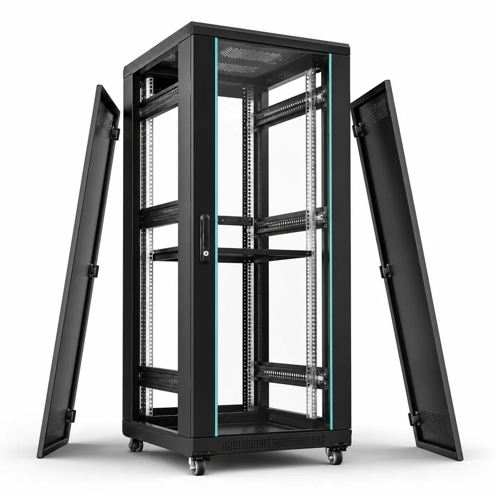
NCT 서버랙에서 통풍 홀 패턴은 장식이나 단순 개구부가 아닙니다. 데이터센터와 통신 장비 랙은 서버 팬이 만든 압력차를 이용해 전면에서 냉기를 흡입하고 후면으로 열기를 배출합니다. 이때 도어 타공률, 홀 피치, 루버 방향, 케이블 개구부, 내부 레일, 블랭킹 패널, 상하부 배기 구조가 모두 냉각 성능에 영향을 줍니다.
NCT 가공은 서버랙 판금 부품에서 반복 타공, 장공, 루버, 절곡 전개, 체결 홀, 케이블 인입구를 빠르고 일정하게 만드는 공정입니다. 하지만 통풍 성능은 구멍을 많이 뚫는 방식으로만 결정되지 않습니다. 공기는 저항이 낮은 경로로 흐르기 때문에 의도하지 않은 틈이 있으면 서버 장비를 통과하지 않고 우회하며, 반대로 타공 패턴이 너무 조밀하거나 도장 후 막힘이 생기면 서버 팬 부하가 커질 수 있습니다.
서버랙의 냉각 효율은 열원, 팬 정압, 판넬 개구율, 랙 내부 장애물, 핫아일과 콜드아일의 분리 정도가 함께 만드는 결과입니다. 특히 고밀도 서버, GPU 장비, 전원 모듈, 네트워크 장비가 혼재되는 랙에서는 단순히 전면 도어를 많이 뚫는 방식보다, 어느 면에서 냉기가 들어가고 어느 면에서 열기가 나가는지를 명확히 분리하는 설계가 더 중요합니다.
따라서 NCT 서버랙 판금 설계는 기계 구조 설계와 열관리 설계가 겹치는 영역입니다. 도어, 측면판, 상부 커버, 하부 베이스, 케이블 패널, 블랭킹 패널은 각각 독립된 부품처럼 보이지만 실제로는 하나의 냉각 유로를 형성합니다. 이 글은 통풍 홀 패턴, 냉각 유로, 압력손실, 판금 강성, 조립 품질을 하나의 기준으로 연결해 살펴봅니다.
서버랙 통풍 설계의 출발점
서버랙 냉각 유로는 전면 흡기, 장비 통과, 후면 배기라는 기본 방향을 갖습니다. 전면 도어와 전면 판넬은 냉기를 받아들이는 면이고, 후면 도어와 상부 배출부는 열기를 내보내는 면입니다. 이 흐름이 중간에서 섞이면 장비 흡입 온도가 올라가고, 냉각 장비는 같은 열부하를 처리하기 위해 더 많은 풍량과 더 낮은 공급 온도를 요구하게 됩니다.
통풍 홀 패턴은 이 흐름의 첫 번째 저항입니다. 원형 홀, 장공, 루버, 슬릿, 육각형 메시 등 어떤 형상을 선택하느냐에 따라 개구율, 압력손실, 분진 유입, 소음, 강성 저하, 도장 품질이 달라집니다. 서버랙 제작자는 홀 면적만이 아니라 서버 팬이 실제로 느끼는 저항과 랙 내부에서 공기가 분배되는 방식까지 함께 봐야 합니다.
NCT 서버랙 설계에서 중요한 것은 통풍 면적과 구조 기준면을 동시에 지키는 것입니다. 도어는 열을 빼내야 하지만 처지면 안 되고, 판넬은 공기를 통과시켜야 하지만 힌지와 래치 기준은 유지해야 합니다. 이 균형이 맞을 때 서버랙 판금 부품은 냉각 부품이자 구조 부품으로 안정적으로 작동합니다.
서버랙 통풍 설계의 출발점은 전체 냉각량을 판넬 면적으로 나누는 방식이 아니라, 장비별 흡기 위치와 배기 위치를 따라 유로를 나누는 방식입니다. 같은 랙 높이 안에서도 전원부, 저장장치, 네트워크 스위치, GPU 서버는 발열 밀도와 팬 방향이 다를 수 있습니다. 타공 영역은 이 장비 배치를 따라 높이별로 달라질 수 있으며, 빈 공간을 남겨 두는 영역과 적극적으로 개방해야 하는 영역을 분리해야 합니다.
개구율은 타공된 면적을 총 판넬 면적으로 나눈 값이지만, 실제 냉각에서는 유효 개구율이 더 중요합니다. 프레임에 가려지는 홀, 도장으로 좁아진 홀, 레일 뒤에 숨은 홀, 케이블로 막힌 개구부는 계산상 면적에 포함되더라도 실제 유량에는 제한적으로만 기여합니다. 그래서 도면 검토에서는 CAD 면적뿐 아니라 조립 후 유효 통풍 면적을 함께 확인해야 합니다.
전면 도어 개구율과 압력손실
전면 도어의 타공률은 서버 팬이 공기를 빨아들이는 조건을 결정합니다. 개구율이 낮으면 도어가 흡입 저항으로 작용하고, 서버 팬은 같은 유량을 얻기 위해 더 높은 속도로 동작해야 합니다. 반대로 개구율만 지나치게 높이면 도어 강성, 보안성, 외부 이물 차단, 필터 적용성, 소음 차폐가 약해질 수 있습니다.
일반적인 설계 검토에서는 도어 개구율을 서버 장비 발열량과 팬 정압의 함수로 보아야 합니다. 고발열 서버가 많이 들어가는 랙은 전면 전체에 균일한 흡기 면적이 필요하고, 특정 위치에 발열 장비가 집중되는 랙은 해당 높이에서 유량 부족이 생기지 않도록 타공 영역을 재배치해야 합니다. 상단이나 하단에만 통풍이 집중되면 일부 장비 흡입부가 상대적으로 불리해질 수 있습니다.
개구율은 홀 직경과 피치로 계산할 수 있지만 실제 유량은 판 두께, 홀 모서리 상태, 도장 막 두께, 도어 프레임, 필터, 서버 전면 베젤의 저항까지 더해져 결정됩니다. 따라서 도면에는 단순히 “타공”이라고 적는 것보다 홀 형상, 피치, 타공 영역, 비타공 보강 구간, 버 방향을 함께 지정하는 편이 안정적입니다.
원형 홀을 사각 배열로 배치하면 개구율은 홀 단면적과 피치 면적의 비율로 접근할 수 있고, 엇갈림 배열에서는 피치와 배열 각도까지 함께 보아야 합니다. 장공 패턴은 같은 폭에서도 길이 방향으로 더 큰 개구를 만들 수 있지만, 하중 방향과 평행하게 길게 뚫으면 판넬의 휨 강성이 약해질 수 있습니다. 서버랙 도어는 통풍판이면서 동시에 큰 면적의 구조판이므로, 홀 형상은 냉각과 처짐을 동시에 검토해야 합니다.
압력손실은 유량이 증가할수록 비선형적으로 커질 수 있습니다. 같은 개구율이라도 홀 가장자리가 거칠거나 버가 흡기 방향으로 서 있으면 국부 난류가 증가하고, 작은 홀에 두꺼운 도장이 쌓이면 유효 단면이 줄어듭니다. NCT 타공 후 버 제거, 모서리 상태, 분체도장 전 세척과 마스킹 기준은 냉각 품질과 직접 연결됩니다.
루버와 측면 유로의 방향성
루버는 원형 타공과 달리 방향성이 있는 통풍 구조입니다. 외부에서 내부가 직접 보이는 것을 줄이고, 물방울이나 큰 이물의 직접 유입을 줄이며, 공기 흐름을 특정 방향으로 유도할 수 있습니다. 하지만 루버 방향이 서버 팬의 흡기와 배기 방향에 맞지 않으면 압력손실이 커지고 일부 영역에서 역류가 생길 수 있습니다.
측면 패널이나 도어 옆면에 루버를 적용할 때는 냉기 유입면과 열기 배출면을 구분해야 합니다. 전면 흡기를 보조하는 루버는 냉기 통로로 작동해야 하고, 후면 또는 측면 배기 루버는 열기가 다시 흡기면으로 돌아가지 않도록 방향을 잡아야 합니다. 같은 루버라도 설치 위치에 따라 흡기 보조 구조가 될 수도 있고 열기 재순환 경로가 될 수도 있습니다.
NCT 가공 관점에서 루버는 성형 높이, 금형 clearance, 절곡선 간섭, 도장 뭉침, 모서리 균열이 핵심 관리 항목입니다. 루버를 절곡선 가까이에 배치하면 성형부가 눌리거나 판넬이 비틀릴 수 있고, 도장 후 개구부가 좁아지면 초기 설계 개구율과 실제 통풍 면적이 달라질 수 있습니다.
루버는 특히 외부 이물과 시선을 제어해야 하는 통신랙, 전장랙, 산업용 서버랙에서 유용하지만, 서버 팬이 요구하는 정압과 맞지 않으면 유량 제한 요소가 됩니다. 루버의 입구 각도와 출구 방향이 공기 흐름을 급격히 꺾으면 국부 손실이 커지고 소음도 증가할 수 있습니다. 따라서 루버는 “막으면서 통과시키는 구조”가 아니라 “방향을 가진 저항체”로 다루는 것이 적절합니다.
측면 유로가 필요한 경우에는 전면 흡기와 후면 배기 흐름을 방해하지 않는 보조 경로로 제한해야 합니다. 측면이 과도하게 열리면 인접 랙의 열기와 섞일 가능성이 있고, 내부 케이블이나 PDU가 측면 흐름을 막으면 특정 높이에서 정체 구간이 생길 수 있습니다. 측면 루버의 위치는 장비 발열 위치, 랙 간격, 벽면 배치, 유지보수 접근성을 함께 고려해야 합니다.
NCT 서버랙 통풍 홀 패턴 설계 매트릭스
셀 위에 커서를 올리면 설계 판단 기준을 확인할 수 있습니다. 개구율은 시작점일 뿐이며 서버랙 냉각 성능은 압력손실, 유로 분리, 판금 강성, 후처리 품질까지 함께 결정됩니다.
| 설계 변수 | 냉각 역할 | NCT 가공 기준 | 검사 항목 | 품질 리스크 | 판단 기준 |
|---|---|---|---|---|---|
| 도어 타공률 | 전면 냉기 유입과 후면 열기 배출의 기본 저항을 결정합니다. | 홀 직경, 피치, 배열 각도, 타공 영역 경계 | 개구율, 홀 변형, 피치 편차, 도장 후 막힘 | 냉기 부족, 팬 부하 증가, 도어 강성 저하 | 서버 팬 정압과 랙 발열량을 기준으로 과도한 저항과 과도한 개방을 피합니다. |
| 홀 형상과 피치 | 공기 분포, 소음, 분진 유입, 시야 차폐를 조정합니다. | 원형 홀, 장공, 슬롯, 60도 엇갈림, 클러스터 타공 | 홀 간 거리, 모서리 찢김, 슬러그 흔적, 버 높이 | 균열, 케이블 피복 손상, 도장 불량, 유로 막힘 | 개구율과 판넬 강성을 동시에 만족하는 피치와 배열을 선택합니다. |
| 루버와 슬릿 방향 | 공기 방향을 유도하고 외부 이물과 직사 유입을 줄입니다. | 성형 높이, 루버 방향, 절곡선 간섭, 금형 clearance | 성형 높이, 개구 균일성, 루버 균열, 도장 뭉침 | 역류, 압력손실 증가, 간섭, 배수성 저하 | 흡기면과 배기면의 방향성을 분리하고 유지보수 접근성을 확보합니다. |
| 케이블과 블랭킹 | 냉기 우회와 열기 재순환을 차단합니다. | 케이블 인입구 위치, 브러시 패널, 블랭킹 패널 체결 홀 | 개구부 크기, 패널 밀착, 체결 위치도, 틈새 | 바이패스 airflow, hot spot, 서버 흡입온도 상승 | 케이블 경로는 후면/측면으로 정리하고 빈 공간은 막아 유로를 유지합니다. |
| 절곡 강성과 보강 | 도어 처짐, 패널 진동, 레일 기준면 변형을 억제합니다. | 플랜지 폭, 비드, 보강 브라켓, 힌지/래치 주변 무타공 구간 | 평탄도, 뒤틀림, 힌지 기준, 체결 후 간극 | 도어 밀폐 불량, 소음, 유로 누설, 조립 공차 누적 | 통풍 면적과 강성 보강을 동시에 만족하도록 타공 제외 구간을 설정합니다. |
| 표면처리와 접지 | 부식 방지, 전기적 안정성, 분진 부착, 유지보수성을 좌우합니다. | 분체도장 전 디버링, 접지면 마스킹, 나사부 도장 관리 | 도장 막 두께, 접지 연속성, 타공부 막힘, 잔류 칩 | 접지 불량, 도장 박리, 케이블 손상, 오염 축적 | 외관면, 통풍면, 접지면, 체결면을 구분해 후처리 기준을 정합니다. |
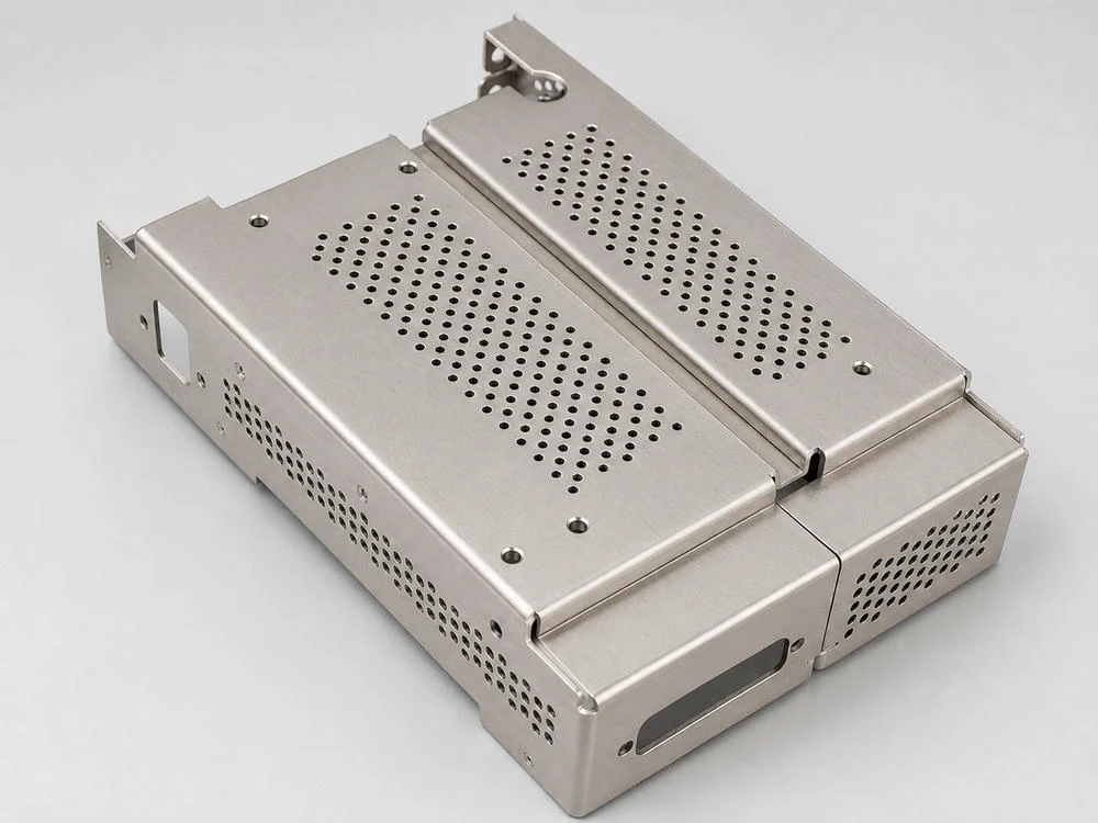
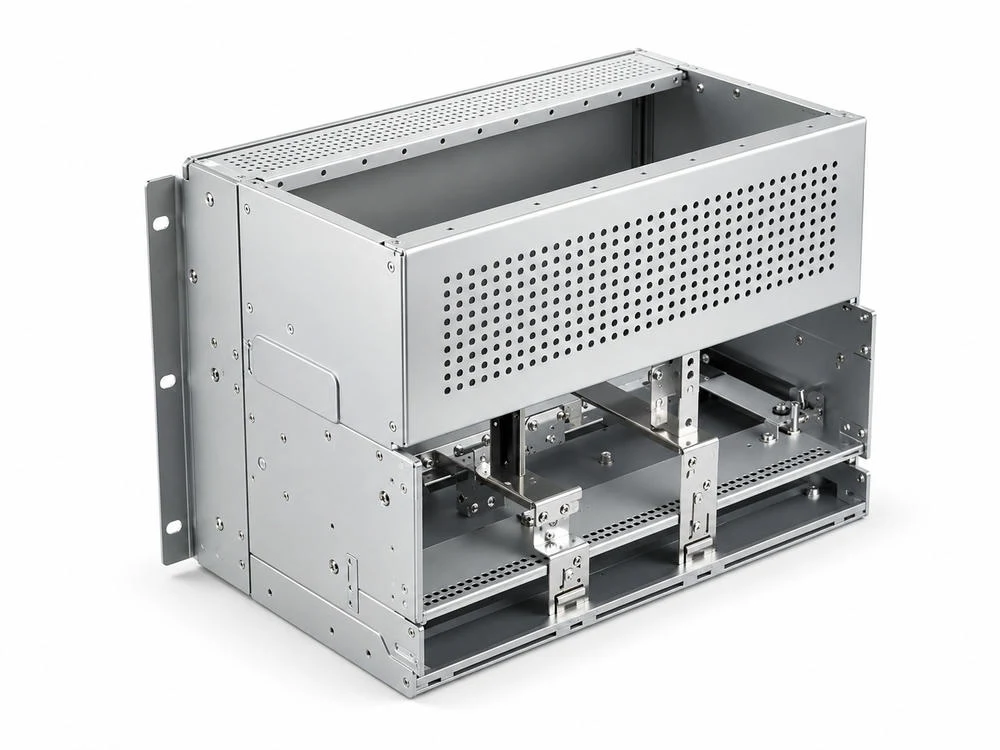
모듈형 섀시의 상하부 냉각 경로
서버랙 내부에는 랙 전체 도어뿐 아니라 전원 모듈, 통신 모듈, 배전부, 슬라이드 레일, 케이블 트레이가 들어가는 모듈형 섀시가 배치됩니다. 이런 부품은 전면과 후면뿐 아니라 상부와 하부에도 통풍 홀이 필요합니다. 장비 높이가 제한될수록 냉각 유로는 좁아지고, 작은 개구부 하나가 유량 분배에 큰 영향을 줄 수 있습니다.
상부 타공은 상승하는 열기를 배출하는 보조 경로가 될 수 있지만, 전면 흡기와 후면 배기 흐름을 깨뜨리면 냉기가 장비를 통과하기 전에 빠져나가는 우회 경로가 될 수 있습니다. 하부 개구부도 마찬가지입니다. 케이블 인입과 배선 정리를 위해 만든 구멍이 냉기 누설 경로가 되면 서버 흡입면으로 가야 할 공기가 랙 바닥이나 후면으로 빠질 수 있습니다.
따라서 모듈형 NCT 섀시는 통풍 홀과 체결 홀을 별도로 보지 않아야 합니다. 장착 브라켓, 레일 기준면, 커버 체결부, 케이블 통과부, 상하부 타공부가 하나의 유로 안에서 작동합니다. 필요한 곳에만 개구를 만들고, 필요 없는 곳은 막아주는 것이 냉각 유로 설계의 기본입니다.
전원 모듈이 포함되는 랙에서는 열원이 랙 후면이나 측면에 집중되는 경우가 많습니다. 이때 전면 도어의 개구율이 충분하더라도 내부 전원부 커버나 케이블 덕트가 흐름을 막으면 국부 온도 상승이 생길 수 있습니다. 모듈형 섀시는 상하부 타공 위치, 내부 배플, 브라켓 형상, 커버 체결 방향을 함께 조합해 열이 머무르는 공간을 줄여야 합니다.
상하부 개구부는 유지보수와 오염 관리 기준도 함께 요구합니다. 바닥 개구부가 넓으면 케이블 작업은 쉬워지지만 먼지 유입과 냉기 바이패스가 커질 수 있고, 상부 개구부가 넓으면 배기에는 유리해도 낙하 이물과 내부 접근성 문제가 생길 수 있습니다. 통풍 설계는 냉각 효율만의 문제가 아니라 장기 운용 환경의 관리 품질까지 포함합니다.
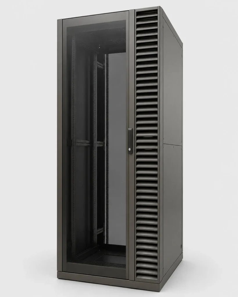
오픈 프레임과 블랭킹 패널
오픈 프레임 서버랙은 도어 저항이 작고 접근성이 좋지만, 공기가 의도한 방향으로만 흐르지 않는다는 문제가 있습니다. 서버가 장착되지 않은 빈 U 공간, 측면 틈, 케이블 홀, 상부 개구부가 열려 있으면 냉기가 장비를 통과하지 않고 빠져나가거나 후면 열기가 전면으로 재순환될 수 있습니다.
블랭킹 패널은 단순 마감 부품이 아닙니다. 빈 장착 공간을 막아 전면 냉기가 서버 흡입구로 들어가게 만들고, 후면 열기가 전면으로 돌아오는 경로를 차단합니다. 고밀도 서버랙에서는 블랭킹 패널, 브러시 패널, 사이드 실링, 케이블 차폐가 통풍 홀 패턴만큼 중요해집니다.
NCT 가공에서는 블랭킹 패널의 체결 홀 위치도, 패널 평탄도, 절곡 플랜지, 장착 탭, 손잡이 장공까지 함께 관리해야 합니다. 패널이 잘 맞지 않으면 작은 틈이 생기고, 그 틈이 반복되면 랙 전체 유로가 무너집니다. 서버랙 냉각은 단일 도어의 개구율보다 전체 조립체의 누설 관리가 더 큰 변수로 작동할 수 있습니다.
블랭킹 패널의 효과는 빈 공간을 막는 데서 끝나지 않습니다. 서버 전면의 압력 분포를 안정시키고, 장비가 설치된 U 위치로 냉기가 집중되도록 돕습니다. 특히 랙 내부에 깊이가 다른 장비가 섞이면 후면 공간에서 열기가 돌아오는 경로가 생기기 쉬우므로, 전면 빈 공간과 측면 틈을 함께 차단해야 합니다.
케이블 홀은 냉각 유로에서 가장 자주 과소평가되는 요소입니다. 케이블을 많이 넣기 위해 개구부를 크게 만들면 작업성은 좋아지지만, 냉기와 열기가 섞이는 통로도 커집니다. 브러시 패널, 분할 커버, 고무 그로밋, 탈착식 판넬을 적용하면 유지보수성을 유지하면서 누설을 줄일 수 있습니다.
서버랙 냉각 유로와 타공 저항 배치
NCT 서버랙의 통풍 설계는 전면 도어의 개구율만으로 결정되지 않습니다. 냉기 유입, 장비 흡입, 내부 누설, 후면 배기, 케이블 개구부, 블랭킹 패널이 한 흐름으로 연결되어야 합니다.
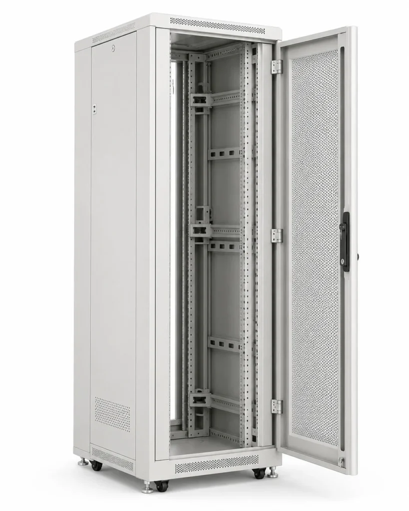
행 단위 서버랙과 데이터센터 냉각
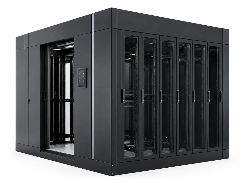
서버랙이 여러 대 연결되는 데이터센터 환경에서는 개별 랙의 통풍 구조가 행 단위 냉각 성능으로 확장됩니다. 콜드아일은 냉기가 공급되는 영역이고 핫아일은 장비에서 나온 열기가 회수되는 영역입니다. 각 랙의 전면과 후면이 이 방향에 맞지 않으면 냉기와 열기가 섞이고, 일부 랙의 흡입 온도가 상승합니다.
행 단위 설계에서는 도어 개구율, 상부 배출부, 바닥 개구부, 케이블 통로, 랙 사이 틈, 측면 패널, 팬 방향을 함께 봐야 합니다. 하나의 랙만 보면 충분한 통풍 면적으로 보여도, 여러 대가 연결되면 상부 누설, 측면 재순환, 하단 바이패스가 누적될 수 있습니다. 이때 냉각 설계는 판금 도면과 데이터센터 공조 조건을 연결하는 작업이 됩니다.
NCT 서버랙 제작자는 장비 설치 전부터 핫아일과 콜드아일의 방향, 바닥 또는 천장 공조 방식, 케이블 인입 위치, 유지보수 동선을 반영해야 합니다. 타공 패턴은 제품 단품의 외관이 아니라 랙 행 전체의 압력 저항 분포를 만드는 요소입니다.
데이터센터에서는 랙 전면의 공급 공기 온도만 보는 것으로 충분하지 않습니다. 장비 흡입면의 높이별 온도, 후면 배기 온도, 랙 상부 재순환, 바닥 타일 풍량, 랙 사이 틈새 흐름이 서로 연결됩니다. NCT 판금 부품의 타공 위치와 차폐 구조가 잘못되면 공조 설비가 충분해도 서버 흡입부에서는 온도 편차가 커질 수 있습니다.
서버랙이 한 줄로 이어지는 환경에서는 판넬 하나의 작은 누설도 반복되며 누적됩니다. 동일한 타공률의 도어라도 랙 사이 틈과 상부 개구부가 다르면 행 전체 압력 분포가 달라집니다. 그래서 서버랙 판금 설계는 단품 인증을 넘어 설치 조건과 운용 조건을 고려하는 방향으로 검토해야 합니다.
도면 사양과 검사 기준의 연결
NCT 서버랙 통풍 구조는 도면 단계에서 사양이 명확하지 않으면 제작 후 품질 편차가 커질 수 있습니다. “전면 타공”, “측면 루버”, “케이블 홀”처럼 기능명만 적힌 도면은 실제 생산에서 홀 피치, 버 방향, 도장 막힘, 절곡 변형, 체결부 간섭을 충분히 통제하기 어렵습니다. 통풍 부품은 도면에 냉각 기능과 판금 기준이 함께 드러나야 합니다.
도면에는 홀 형상, 홀 직경, 피치, 배열 방식, 타공 영역 경계, 무타공 보강 폭, 절곡선 이격 거리, 루버 방향, 루버 성형 높이, 케이블 홀 차폐 구조, 표면처리 제한면, 접지면, 검사 항목이 함께 연결되어야 합니다. 이 정보가 분리되면 설계자는 냉각만 보고, 제작자는 가공성만 보고, 조립자는 체결성만 보는 문제가 생길 수 있습니다.
검사 기준도 치수 검사에 머물러서는 부족합니다. 통풍 홀 막힘, 버 잔류, 도장 뭉침, 패널 뒤틀림, 힌지 기준면 처짐, 래치 체결력, 블랭킹 패널 밀착, 케이블 홀 차폐 상태, 접지 연속성까지 확인해야 실제 운용 품질과 연결됩니다. 서버랙은 장시간 설치되는 구조물이므로 초기 치수뿐 아니라 반복 개폐와 유지보수 후에도 유로가 유지되는지가 중요합니다.
구매와 제작 협의에서는 타공률 수치만 비교하기보다 랙에 들어갈 장비의 열부하, 팬 방향, 케이블 양, 유지보수 빈도, 설치 환경을 함께 공유하는 것이 바람직합니다. 같은 NCT 서버랙이라도 통신실, 데이터센터, 산업 제어반, 전원 모듈 랙은 요구되는 개구율과 차폐 기준이 달라질 수 있습니다.
NCT 서버랙 품질 기준의 핵심
NCT 서버랙 통풍 설계의 핵심은 개구율, 압력손실, 강성, 누설 차단을 하나의 기준으로 묶는 것입니다. 구멍을 크게 늘리면 저항은 줄어들 수 있지만 도어 처짐과 패널 진동이 커질 수 있습니다. 반대로 구조 강성을 우선하면 공기 흐름이 부족해질 수 있습니다. 서버랙 판금은 이 두 조건을 동시에 만족해야 합니다.
타공 영역은 장비 흡입구와 배기구의 위치를 기준으로 배치하고, 절곡 플랜지와 힌지 주변에는 충분한 무타공 보강 구간을 남겨야 합니다. 케이블 개구부는 차폐 또는 브러시 패널로 관리하고, 빈 U 공간은 블랭킹 패널로 막아야 합니다. 분체도장 전후에는 타공부 막힘, 버, 잔류 칩, 접지면 상태까지 확인해야 합니다.
도면 기준에서는 홀 직경, 피치, 배열, 타공 영역, 무타공 보강부, 절곡선 이격, 루버 방향, 케이블 홀 차폐 방식, 접지면, 표면처리 조건이 함께 지정되어야 합니다. 검사 기준에서는 개구부 막힘, 버 방향, 도장 두께, 평탄도, 뒤틀림, 체결 홀 위치, 블랭킹 패널 밀착 정도가 냉각 품질과 구조 품질을 동시에 판단하는 항목이 됩니다.
서버랙이 고밀도 장비를 수용할수록 냉각 유로는 단순한 공기 통로가 아니라 시스템 신뢰성의 일부가 됩니다. 냉기가 장비를 통과하지 않고 우회하면 팬 전력과 소음이 증가하고, 열기가 전면으로 되돌아오면 장비 흡입 온도가 올라갑니다. 이 문제는 공조 설비만으로 해결하기 어렵고, 판금 부품의 타공 패턴과 차폐 구조에서 먼저 관리되어야 합니다.
NCT 서버랙 통풍 홀 패턴은 냉각 효율과 판금 강성을 동시에 설계하는 기술 요소이며, 냉기 유입과 열기 배출이 분리된 유로 안에서 반복 조립 품질까지 유지될 때 서버랙 냉각 성능이 안정됩니다.
English Technical Overview
NCT Server Rack Ventilation and Cooling Path Design
NCT server rack ventilation should not be treated as a decorative perforation pattern. In data-center and telecom equipment racks, airflow follows a pressure path created by server fans, room cooling systems, front doors, rear doors, cable openings, blanking panels, and internal structural members. A punched sheet-metal panel becomes part of this pressure network.
The basic cooling direction is simple: cold air should enter the front of the rack, pass through the IT equipment, and leave through the rear or return path. The engineering challenge is keeping that path stable. If cold air bypasses the equipment through cable holes or empty rack units, the effective cooling airflow is reduced. If hot exhaust recirculates to the front intake, the server inlet temperature rises and the cooling system must work harder.
NCT punching is well suited for server rack panels because it can create repeated holes, slots, louvers, cable openings, mounting holes, and bend-ready sheet-metal blanks with high productivity. However, the performance of the rack depends on more than the number of holes. Hole geometry, pitch, open area, panel stiffness, coating thickness, burr direction, grounding faces, and assembled gaps must be reviewed together.
The important distinction is the difference between gross open area and effective open area. Gross open area is the perforated area visible on a drawing. Effective open area is the portion that remains useful after frames, rails, handles, hinges, filters, cable bundles, coating buildup, and internal equipment geometry are considered. A rack can have a visually generous perforation pattern and still create a restrictive inlet if the useful flow path is blocked after assembly.
Server rack ventilation also has to be evaluated by height. A rack populated with mixed equipment does not release heat uniformly. Network switches, power modules, storage arrays, and AI servers may use different airflow directions and different fan curves. The punching layout should therefore support the equipment map rather than apply the same perforation density everywhere without thermal logic.
Open Area, Pressure Drop, and Rack Door Impedance
Open area is the first measurable variable in a perforated rack door. It describes how much of the gross panel area is physically open. A larger open area generally reduces airflow resistance, but it does not automatically guarantee better cooling. The real pressure drop also depends on hole shape, panel thickness, edge quality, coating buildup, filters, door frame geometry, and the fan curve of the installed equipment.
For a server rack, the front and rear doors are not passive surfaces. They add resistance before and after the equipment. When the door resistance is too high, server fans may lose flow or increase speed. When the door is too open but the inside of the rack is not sealed, air can bypass the equipment. A useful rack design therefore balances open area with directional airflow control.
Round holes, staggered patterns, slots, and louvers each behave differently. Round holes are stable and easy to repeat. Slots can provide directional visual rhythm and larger openings but may weaken the sheet along one direction. Louvers can guide air and reduce direct ingress, but they also create a directional resistance and require careful forming control.
For round perforations, the open area can be estimated from hole diameter and pitch. For staggered patterns, the pitch relationship between adjacent rows changes both the open area and the remaining web width. For slots, the long direction changes bending behavior because the sheet loses continuity along the slot axis. For louvers, the formed angle and height become part of the airflow resistance, so the drawing must control the direction as well as the size.
Pressure drop is not only a thermal issue. It affects acoustics, fan energy, dust behavior, and service life. If the front door creates too much resistance, equipment fans may increase speed, raising noise and power consumption. If the rear door or exhaust path is restrictive, hot air can accumulate behind equipment. If the top or cable zones are too open, cooling air can escape before it reaches the intended equipment face.
NCT Server Rack Airflow Design Matrix
This matrix mirrors the Korean technical table for international B2B readers. Open area is only the starting point; pressure drop, airflow separation, sheet-metal stiffness, burr control, and coating quality must be evaluated together.
| Design Variable | Cooling Role | NCT Control Point | Inspection Item | Quality Risk | Decision Logic |
|---|---|---|---|---|---|
| Door open area | Controls basic resistance for cold-air intake and hot-air exhaust. | Hole diameter, pitch, stagger angle, perforated zone boundary | Open area, hole distortion, pitch deviation, coating blockage | Insufficient intake air, higher fan load, lower door stiffness | Avoid both excessive resistance and uncontrolled open leakage by matching rack heat load and fan pressure. |
| Hole shape and pitch | Adjusts air distribution, noise, dust entry, and visual shielding. | Round holes, slots, staggered patterns, cluster punching | Web distance, tearing, slug marks, burr height | Cracking, cable sheath damage, coating defects, blocked flow | Select the pitch pattern that balances open area and panel stiffness. |
| Louvers and slots | Guide airflow direction and reduce direct ingress of foreign matter. | Forming height, louver direction, bend-line clearance, tooling clearance | Form height, opening uniformity, cracks, coating buildup | Reverse flow, added pressure drop, interference, poor drainage | Separate intake and exhaust directions while keeping maintenance access. |
| Cable and blanking | Prevents cold-air bypass and hot-air recirculation. | Cable-entry position, brush panel, blanking-panel hole pattern | Opening size, panel seal, fastening position, gap width | Bypass airflow, hot spots, higher server inlet temperature | Route cables to rear or side zones and close unused spaces to preserve airflow direction. |
| Bending stiffness | Controls door sag, panel vibration, and rail datum stability. | Flange width, bead, reinforcement bracket, no-punch zones around hinges | Flatness, twist, hinge datum, assembled gap | Poor sealing, noise, air leakage, tolerance stack-up | Set non-perforated structural zones around hardware and bend features. |
| Coating and grounding | Supports corrosion control, electrical stability, dust behavior, and service safety. | Deburring before coating, ground-face masking, thread coating control | Coating thickness, grounding continuity, blocked perforations, chip residue | Poor grounding, coating peel, cable damage, contamination buildup | Separate cosmetic surfaces, ventilation surfaces, grounding faces, and fastening faces. |
Hot Aisle, Cold Aisle, and Airflow Separation
Data-center rack cooling is based on separation. Cold air should stay on the intake side, and hot exhaust should return on the discharge side. Hot aisle and cold aisle layouts are used because mixed air reduces cooling efficiency and raises inlet temperatures. A rack door or side panel should support this separation rather than defeat it.
Perforated front doors are useful when the installed equipment follows front-to-rear airflow. Rear doors should also allow hot exhaust to leave without excessive resistance. At the same time, unused rack units, cable openings, and side gaps should be controlled. Otherwise, cold supply air may leak around equipment, while hot exhaust may recirculate toward the front.
Blanking panels, brush grommets, side sealing strips, and controlled cable pathways are therefore part of the cooling design. They are not accessories added after the rack is built. For NCT sheet-metal design, their mounting holes, slots, tabs, and clearances should be planned together with the main perforation pattern.
Cold aisle and hot aisle separation becomes more critical as rack density increases. A single rack with moderate heat load may tolerate some leakage, but a row of racks repeats the same leakage path many times. Top gaps, side gaps, cable cutouts, and unused rack units can add together until a large fraction of supplied air no longer passes through active equipment.
Airflow separation should be visible in the mechanical structure. The front side should support controlled intake, the rear side should support exhaust, and unused openings should have defined covers. If a rack uses side intake or side exhaust, that exception should be intentional and should not compromise neighboring rack airflow. The most reliable design is one in which service access, cabling, and ventilation do not compete with each other.
NCT Sheet-Metal Manufacturing Factors
NCT punching introduces manufacturing constraints that directly affect ventilation quality. Hole diameter, pitch, web distance, edge distance, bend-line distance, tool wear, slug control, and burr direction must be considered before the flat pattern is released. A ventilation pattern that looks efficient in CAD may create weak edges, burr-heavy holes, or distortion after bending.
Panels with high perforation density can lose bending stiffness. Door sag, latch misalignment, hinge distortion, and vibration can appear when the perforated zone is too close to structural features. Reinforcing flanges, beads, unpunched borders, hinge-side no-punch zones, and local brackets can preserve stiffness without completely blocking airflow.
Surface finishing also changes the final result. Powder coating can reduce effective hole size, bridge small perforations, or create uneven edges if the punched holes are not deburred properly. Grounding areas and fastening faces may need masking or post-treatment review. For server rack panels, coating quality, grounding continuity, and clean ventilation openings all matter.
Material selection changes both mechanical and cooling behavior. Carbon steel, galvanized steel, stainless steel, and aluminum each respond differently to punching, forming, coating, grounding, corrosion exposure, and vibration. Thin panels improve weight and workability but require careful reinforcement. Thicker panels preserve stiffness but may increase punching load, burr height, and edge resistance around small perforations.
The tooling sequence also matters. Dense perforation before bending can cause distortion, especially near long edges, hinge zones, and latch areas. Louvers near bend lines can collapse or twist if the forming order is not controlled. Cable cutouts with sharp inside corners can concentrate stress unless the radius, edge distance, and fastening layout are reviewed. These manufacturing details become thermal details because distortion and gaps change the airflow path.
Cooling Path Design for Rack Assemblies
A rack assembly should be evaluated as a flow path, not as a collection of panels. Front perforation, equipment intake, internal rails, cable managers, power distribution units, blanking panels, rear perforation, and top exhaust areas all interact. The path of least resistance may not be the path that cools the equipment.
For example, an oversized cable opening can behave like a large bypass vent. An empty rack space can let cold air pass directly to the rear without cooling any server. A poorly sealed side panel can allow hot exhaust to return to the front. These problems are often solved by sheet-metal details: cover plates, brush panels, blanking panels, baffles, or controlled slots.
The best NCT server rack design is therefore not the most open design. It is the design that delivers the right amount of air to the right equipment location while maintaining structural stability, service access, cable safety, grounding, coating durability, and repeatable assembly quality.
A useful rack-level review begins by tracing air rather than drawing holes. The reviewer should identify the cold-air inlet, the equipment intake plane, the heat-generation zone, the exhaust plane, the return path, and possible leakage loops. Each punched panel can then be assigned a role: intake, exhaust, pressure relief, service access, cable management, or structural closure. Holes without a clear role often become bypass paths.
Inspection should also follow the flow path. Door flatness, hinge alignment, latch engagement, blanking-panel fit, cable-gland closure, coating blockage, burr condition, and grounding continuity should be checked as connected items. A rack that is dimensionally acceptable but poorly sealed can perform badly in operation. A rack that has high open area but weak stiffness can create long-term alignment and vibration problems.
Practical Design Standard for NCT Server Racks
A practical specification should begin with heat load and airflow direction. The designer should define front intake, rear exhaust, optional top exhaust, cable-entry zones, and rack unit blanking requirements. Then the perforation pattern can be selected based on open area, pressure drop, stiffness, manufacturability, and finishing requirements.
The drawing should not simply call out “perforated panel.” It should define hole type, pitch, pattern boundary, no-punch zones, bend clearance, burr direction, deburring requirement, coating limitation, grounding surfaces, and inspection points. For louvered panels, forming height and direction should also be specified because the airflow performance is directional.
A high-quality NCT server rack is a sheet-metal airflow system. It must let cold air enter, guide it through equipment, prevent bypass leakage, exhaust hot air, preserve structural stiffness, and remain safe for cable routing and maintenance. When ventilation and fabrication are planned together, the rack becomes a cooling component rather than just an enclosure.
For procurement and production, the specification can be divided into four groups. The thermal group defines airflow direction, target perforated zones, blocked zones, and cable sealing requirements. The structural group defines flange width, hinge-side reinforcement, latch-side stiffness, and allowed flatness. The manufacturing group defines NCT tool conditions, minimum web, minimum edge distance, burr direction, deburring, and coating control. The inspection group defines visual quality, dimensional tolerance, assembly fit, grounding continuity, and blocked-hole limits.
This approach makes the rack easier to communicate across design, purchasing, fabrication, assembly, and field maintenance. It prevents the ventilation pattern from being treated as a cosmetic request and turns it into a repeatable engineering requirement. In high-density server applications, that difference is important because cooling stability depends on many small sheet-metal decisions working together.
추가 정보
검색엔진용 요약
NCT 서버랙 통풍 홀 패턴은 서버 장비의 냉기 유입, 열기 배출, 압력손실, 케이블 누설, 판금 강성을 함께 결정하는 설계 요소입니다. 타공률, 홀 피치, 루버 방향, 절곡 보강, 표면처리, 버 관리를 함께 검토해야 서버랙 판금 부품의 냉각 유로가 안정됩니다.
핵심 포인트 정리
- NCT 서버랙은 타공률만 높이는 방식보다 냉기 유입면과 열기 배출면의 압력 균형을 먼저 검토해야 합니다.
- 원형 홀, 장공, 루버, 슬릿은 개구율, 압력손실, 강성, 버 관리 기준이 서로 다릅니다.
- 전면 도어와 후면 도어는 서버 팬의 전후면 유동 방향과 맞아야 하며, 상하부 누설 경로를 함께 막아야 합니다.
- 케이블 인입구와 빈 장착 공간은 냉기 우회와 열기 재순환을 만드는 주요 원인이 될 수 있습니다.
- 타공 영역은 절곡선, 체결 홀, 힌지, 래치, 레일 기준면과 간섭하지 않도록 NCT 전개 단계에서 관리해야 합니다.
- 버 방향, 표면처리, 분체도장 막 두께, 접지면 마스킹은 서버랙 조립성과 유지보수 안정성에 영향을 줍니다.
FAQ
NCT 서버랙에서 통풍 홀 패턴은 왜 중요합니까?
통풍 홀 패턴은 공기가 들어오고 나가는 면적뿐 아니라 압력손실과 공기 분포를 결정합니다. 타공률이 높아도 케이블, 블랭킹 패널, 내부 레일, 도어 구조가 맞지 않으면 냉기가 서버 흡입구까지 안정적으로 도달하지 못할 수 있습니다.
서버랙 도어는 개구율이 높을수록 좋습니까?
개구율이 높으면 저항은 낮아지지만 도어 강성, 보안성, 분진 유입, 필터 적용성, 소음 조건이 함께 달라집니다. 일정 수준 이상에서는 개구율 증가보다 랙 내부 유로 정리와 누설 차단이 더 큰 영향을 줄 수 있습니다.
루버와 원형 타공은 어떤 차이가 있습니까?
원형 타공은 균일한 개구율과 생산성이 장점이고, 루버는 공기 방향을 유도하거나 외부 이물 유입을 줄이는 데 유리합니다. 다만 루버는 성형 높이와 방향성이 있어 절곡 간섭, 도장 두께, 청소성까지 함께 검토해야 합니다.
케이블 개구부가 냉각 효율에 영향을 줍니까?
케이블 개구부는 의도하지 않은 큰 누설 경로가 될 수 있습니다. 막히지 않은 개구부는 냉기가 서버 장비를 통과하지 않고 우회하거나, 열기가 흡입면으로 재순환되는 원인이 됩니다.
NCT 타공 판넬에서 버 관리는 왜 필요합니까?
타공 버는 케이블 피복 손상, 작업자 안전, 분체도장 불량, 접지면 품질, 팬 흡입부 오염에 영향을 줄 수 있습니다. 서버랙 판금에서는 타공 방향과 후처리 기준을 설계 단계에서 정하는 것이 중요합니다.
서버랙 냉각 유로는 어떤 기준으로 설계해야 합니까?
전면 냉기 유입, 장비 흡입, 후면 배기, 상부 배출, 케이블 경로, 블랭킹 패널, 도어 개구율을 하나의 흐름으로 연결해야 합니다. 냉각 성능은 개별 타공 면적보다 랙 내부의 공기 흐름이 의도한 경로를 유지하는지에 따라 달라집니다.
관련 주제 확장 설명
개구율과 압력손실
개구율은 통풍 가능 면적을 나타내지만 실제 유량은 홀 형상, 판 두께, 유속, 팬 정압, 내부 장애물에 따라 달라집니다. 서버랙 설계에서는 개구율과 압력손실을 동시에 보아야 합니다.
판금 강성과 절곡 보강
타공이 많아지면 판넬 강성이 낮아질 수 있습니다. 절곡 플랜지, 비드, 레일, 보강 브라켓은 통풍 면적을 유지하면서 도어 처짐과 비틀림을 줄이는 기준이 됩니다.
핫아일과 콜드아일
데이터센터 서버랙은 전면 흡기와 후면 배기를 기준으로 배치됩니다. 냉기와 열기가 섞이지 않도록 도어, 블랭킹 패널, 케이블 차폐, 상하부 개구부를 함께 관리해야 합니다.
내부 링크
ID METAL의 최신 제조 기술 글은 인사이트에서 확인할 수 있으며, NCT 서버랙과 타공 판넬 설계는 NCT 정밀판금부품가공 항목과 직접 연결됩니다. 절곡과 판금 케이스 구조는 정밀프레스가공 부품, 체결 브라켓과 레일류는 구조연결용 부품 관점에서도 함께 볼 수 있습니다.
서버랙 내부 배선과 케이블 인입구 설계는 케이블와이어 하네스, 전력 모듈 접촉 안정성은 전기접점, 금속 접합 구조는 브레이징 및 금속접합소재, 정밀 절삭 부품은 cnc정밀가공부품과도 연결됩니다.