
프레스 톤수 선정:
타발력·성형력·에너지와 설비 선택 기준
프레스 톤수는 제품을 누르는 힘의 한계이지, 모든 금형과 소재를 가공할 수 있다는 보증은 아닙니다. 같은 200톤급이라도 하중이 걸리는 높이, 한 번의 가공에 필요한 에너지, 금형의 크기와 하중 중심에 따라 적합한 공정이 달라집니다. 계산상 타발력이 충분히 낮아도 연속 운전에서 속도가 떨어지거나, 편심하중 때문에 한쪽 버와 치수 편차가 커질 수 있습니다.
설비 선정의 출발점은 제품 두께가 아니라 공정별 하중이 언제, 어디에서, 얼마나 오래 발생하는지입니다. 프레스의 능력곡선에 금형 하중을 대조하고, 실제 소재와 목표 생산속도로 품질을 검증해야 설비 능력이 양산 경쟁력으로 이어집니다.
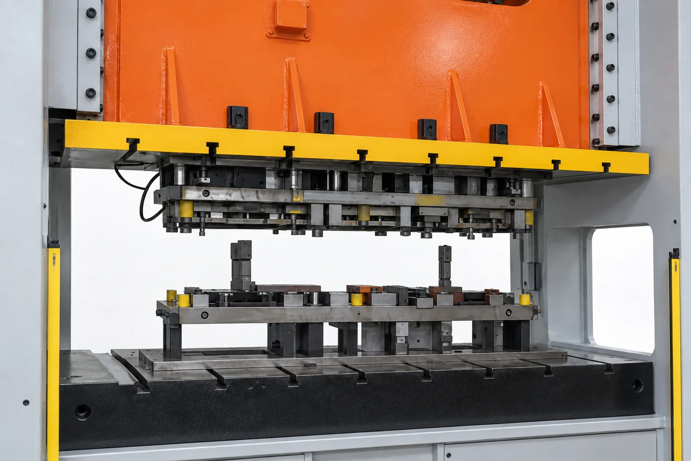
프레스 톤수와 세 가지 능력
현장에서 말하는 ‘톤’은 통상 힘을 나타내는 톤힘(tf)입니다. 질량 단위와 구분해야 하며, 1 tf는 약 9.81 kN입니다. 따라서 100 tf는 약 981 kN이고, 사양서의 1,000 kN을 정확히 100 tf와 같은 값으로 취급하면 안 됩니다. 계산과 설비 비교의 기준 단위를 kN으로 통일하면 혼동을 줄일 수 있습니다.
| 선정 항목 | 판단 기준 | 놓치기 쉬운 조건 |
|---|---|---|
| 가압 능력 | 프레임·슬라이드 등이 허용하는 하중 | 총하중뿐 아니라 각 연결점과 국부 부위의 제한 |
| 토크 능력 | 해당 스트로크 위치에서 구동계가 전달할 수 있는 하중 | 정격능력 발생 위치보다 높은 곳에서 시작되는 성형 |
| 작업 능력 | 한 스트로크에 공급할 수 있는 가공 에너지 | 생산속도, 연속 운전, 구동 방식에 따른 공급 한계 |
기계식 프레스는 명판 하중, 토크 곡선, 에너지 조건을 모두 충족해야 합니다. 서보 프레스 역시 설정된 모션에서의 토크·에너지·열적 제한을 확인해야 하며, 유압 프레스도 가압 속도와 유량·동력·연속 사용 조건을 별도로 검토합니다. 구동 방식이 달라지면 확인할 사양도 달라집니다.
타발력 계산과 절단 길이
타발력의 1차 추정은 동시에 절단하는 길이, 판 두께, 해당 조건의 전단저항을 곱해 구합니다. 외곽만 계산하지 말고 같은 순간에 가공하는 구멍, 슬롯, 노칭과 분리 절단부까지 포함해야 합니다. 다열 금형은 한 피치에서 가공되는 제품 수와 각 공정의 동시 작동 여부를 함께 확인합니다.
타발력 계산 예
동시 절단 길이 400 mm × 판 두께 1.0 mm × 가정 전단저항 300 N/mm²
타발력 = 120,000 N = 120 kN ≈ 12.2 tf
두께가 1.05 mm, 전단저항이 330 N/mm²로 높아지는 가정에서는 138.6 kN으로 약 15.5% 증가합니다. 특정 강종의 보증값이 아니라 입력값 변화에 따른 계산 예입니다.
이 값에 스프링이나 패드의 반력, 다른 성형 공정의 하중이 같은 시점에 더해지는지를 검토합니다. 계산 결과가 12.2 tf라고 해서 바로 그와 가까운 정격의 설비를 선택하는 방식은 적절하지 않습니다. 두께 공차, 소재 강도 범위, 날 마모와 실제 하중곡선을 반영한 운전 여유가 필요합니다.
전단저항은 재질명 하나로 고정되지 않습니다. 공급 상태와 가공경화, 클리어런스, 절단 속도와 윤활의 영향을 받습니다. 인장강도에 일정 계수를 곱하는 방법은 초기 추정에 사용할 수 있지만, 정밀 견적이나 금형 승인에는 소재 자료와 시험 하중으로 보정해야 합니다.
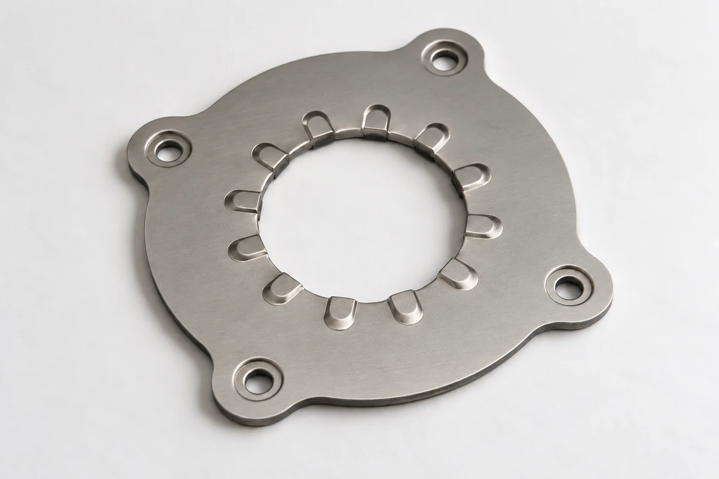
스트리핑력·역하중과 금형 마모
펀치가 판을 뚫는 순간만이 하중 구간은 아닙니다. 하강 중에는 소재를 잡는 가동 스트리퍼의 반력이 더해질 수 있고, 복귀 중에는 펀치에 붙잡힌 소재를 떼어내는 힘이 발생합니다. 어떤 힘이 프레스에 전달되는지는 스트리퍼와 스프링, 패드의 배치 및 반력 경로에 따라 달라집니다.
절단 완료 순간에는 금형과 설비에 저장된 탄성 에너지가 급격히 풀리면서 충격과 역방향 하중이 생길 수 있습니다. 이를 단순히 ‘최대 하중에 몇 퍼센트 추가’하는 것으로 끝내지 말고, 제조사의 역하중 허용치와 금형 구조를 확인해야 합니다. 큰 소음과 진동을 더 높은 톤수만으로 해결하려 하면 원인을 놓칠 수 있습니다.
펀치나 다이에 전단각을 주면 절단 시점을 분산해 최대 타발력을 낮출 수 있습니다. 다만 절단에 필요한 일을 없애는 방법은 아니며, 제품 휨과 횡력, 스크랩 배출도 검토해야 합니다. 재연마 기준은 버 높이와 절단면 상태, 하중 추세를 함께 보고 정하는 것이 합리적입니다.
절곡·드로잉·코이닝의 성형하중
타발력 계산식은 절곡이나 드로잉의 하중식이 아닙니다. 절곡에서는 소재 강도와 판 두께, 굽힘 길이, 금형 개구와 접촉 방식이 하중을 좌우합니다. 에어 벤딩과 바텀 벤딩, 코이닝은 소재가 금형에 구속되는 정도가 다르므로 같은 형상을 만들더라도 필요한 힘이 달라집니다.
| 공정 | 하중에 영향을 주는 항목 | 설비 선정의 추가 확인 |
|---|---|---|
| 타발·피어싱 | 절단 길이, 두께, 전단저항, 날 상태 | 최대 하중, 파단 충격, 복귀 하중 |
| 절곡 | 강도, 두께, 굽힘 길이, 금형 개구 | 성형 시작 높이, 스프링백, 하중 분포 |
| 드로잉 | 블랭크 형상, 드로잉비, 마찰, 반경, 소재 유입 | 긴 작동 거리의 에너지, 홀더·쿠션 조건 |
| 코이닝·리스트라이크 | 국부 접촉 면적, 유동응력, 압하량, 구속 | 하사점 근처 하중, 국부 압력, 금형·프레스 강성 |
드로잉에서는 블랭크 홀더가 소재 유입을 조절합니다. 구속이 부족하면 주름이 생기고 과도하면 파단 위험이 커질 수 있습니다. 홀더 힘을 슬라이드 하중에 합산할지는 단동·복동과 쿠션 구조에 따라 달라지므로, 금형의 실제 반력 경로를 기준으로 계산해야 합니다.
고강도 소재는 단순히 더 큰 힘만 요구하는 것이 아닙니다. 굽힘 반경과 스프링백, 마찰 조건과 성형 속도의 허용 범위도 달라집니다. 큰 프레스를 선택해도 잘못된 소재 유입이나 과도한 국부 변형은 해결되지 않습니다.
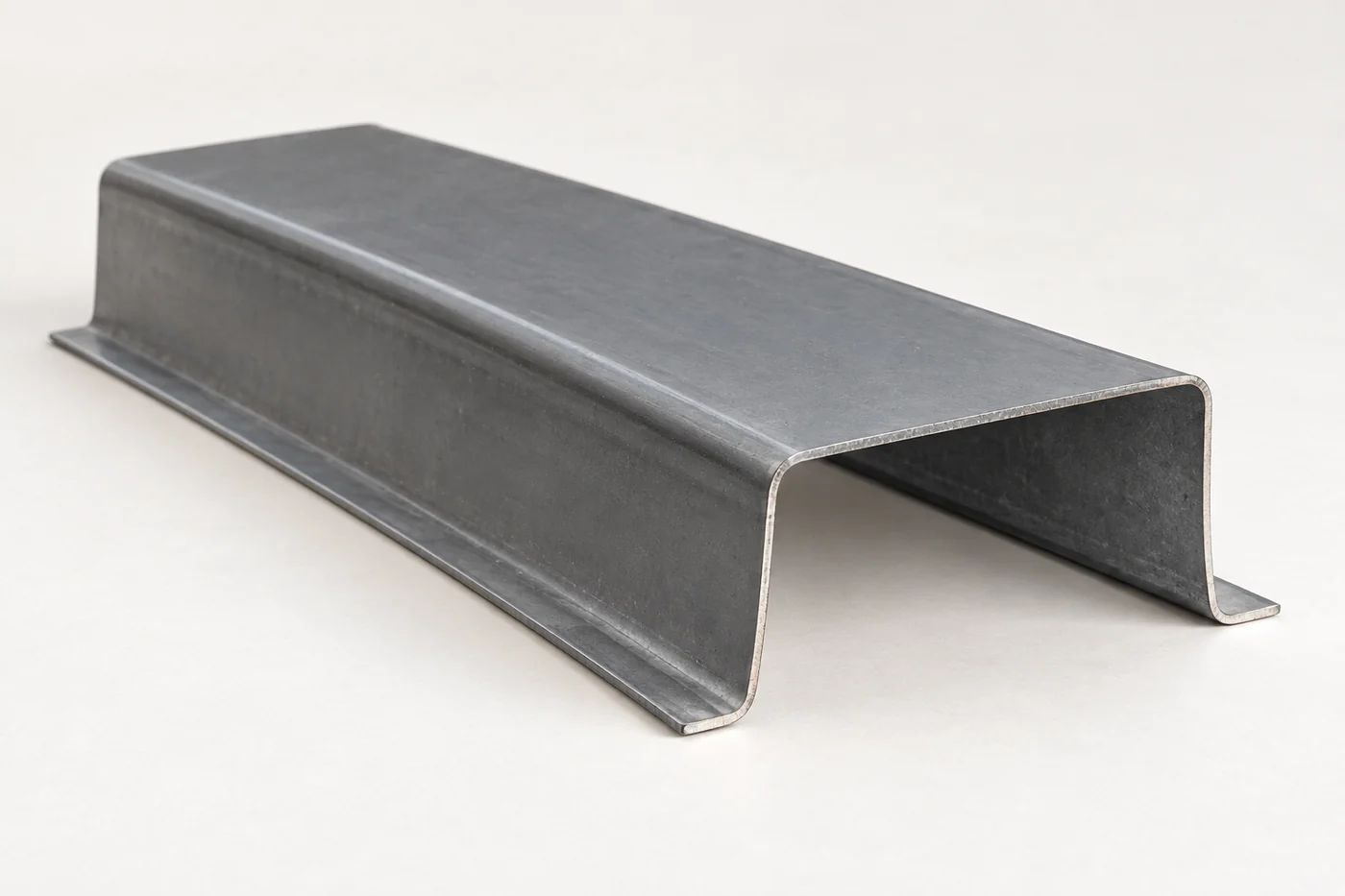
정격능력 발생 위치와 하중곡선
크랭크식 프레스의 정격능력은 보통 하사점 위 특정 거리에서 정의됩니다. ‘정격능력 발생 위치 6 mm’는 하사점 위 6 mm 부근까지 내려왔을 때 정해진 가압 능력을 사용할 수 있다는 뜻입니다. 그보다 높은 위치에서는 구동 토크의 제한 때문에 허용하중이 낮아질 수 있습니다.
따라서 제품의 총 성형 깊이와 프레스의 전체 스트로크만 비교해서는 부족합니다. 금형이 소재에 처음 닿는 위치부터 공정이 끝나는 위치까지, 요구 하중곡선이 설비의 허용곡선 안에 있는지 겹쳐 봐야 합니다. 최대 하중이 발생하는 위치만 확인해도 초기 성형 구간의 과부하를 놓칠 수 있습니다.
예를 들어 정격이 1,100 kN인 프레스라도 하사점 위 10 mm에서 허용되는 힘은 그보다 작을 수 있습니다. 이때 800 kN의 성형이 ‘정격 이하’라는 이유만으로 가능하다고 판정하면 안 됩니다. 반대로 하사점에 가까워졌다고 명판의 구조적 허용하중을 넘어 사용해도 되는 것은 아닙니다.
가공 에너지와 연속 생산 속도
힘은 순간적으로 얼마나 세게 누르는지, 에너지는 힘을 가하면서 얼마나 이동했는지를 나타냅니다. 평균 100 kN의 하중으로 20 mm를 성형하면 가공에 필요한 일은 약 2 kJ입니다. 최대 하중이 같아도 짧게 절단하는 공정과 긴 거리를 밀어 넣는 드로잉은 에너지 요구량이 다릅니다.
에너지는 하중–변위 곡선 아래 면적으로 계산합니다. 최대 하중에 프레스의 전체 스트로크를 곱하면 실제 가공 일을 과대평가할 수 있습니다. 반대로 타발 순간만 계산하고 패드 압축이나 다른 동시 성형을 빠뜨리면 필요한 일을 과소평가할 수 있습니다.
플라이휠식 기계 프레스는 가공 때 소비한 에너지를 다음 스트로크까지 보충해야 합니다. 2 kJ의 공정을 분당 60회 수행하면 가공 일만으로 평균 2 kW에 해당하지만, 이것이 필요한 모터 정격이라는 뜻은 아닙니다. 기계 손실, 회복 시간과 허용 속도 저하를 반영해야 합니다.
저속화가 항상 해결책도 아닙니다. 플라이휠 회전속도가 낮아지면 저장 에너지가 줄 수 있고, 서보 설비는 모션과 반복 주기에 따라 사용 가능한 에너지가 달라집니다. 사양서의 무부하 SPM을 그대로 양산속도로 사용하지 말고, 목표 조건의 연속 작업 능력을 확인해야 합니다.
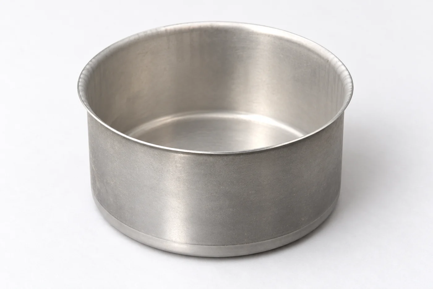
프로그레시브 금형의 편심하중
금형을 볼스터 중앙에 놓았다고 하중도 중앙에 작용하는 것은 아닙니다. 한쪽 스테이션에 큰 타발과 코이닝이 모여 있으면 하중 중심이 그 방향으로 이동합니다. 여러 공정의 최대값이 서로 다른 시점에 발생하므로, 각 공정의 최대 하중을 단순 합산한 값과 실제 순간 총하중도 다를 수 있습니다.
이해를 위한 예로 중앙 왼쪽 100 mm에서 60 kN, 오른쪽 100 mm에서 20 kN이 동시에 작용하면 합력은 80 kN이고 그 위치는 중앙보다 왼쪽 50 mm입니다. 금형 외형의 중심이 아니라 각 힘의 크기와 위치로 결정되는 중심입니다. 다른 시점에는 이 중심이 다시 달라질 수 있습니다.
편심하중은 슬라이드 기울어짐과 금형 클리어런스 변화로 이어져 한쪽 마모나 치수 편차를 유발할 수 있습니다. 다만 같은 증상이 정렬 불량과 소재 편차에서도 나타나므로, 증상 하나로 원인을 단정하지 않습니다. 설비의 좌우·전후 편심 허용곡선과 연결점별 한계를 함께 대조해야 합니다.
개선 방향은 스테이션 배치와 작동 시점, 금형 위치 및 설비 구조를 함께 검토하는 것입니다. 임의의 더미 하중을 추가하거나 금형 가이드포스트에 설비의 기울어짐을 억지로 맡기는 방법은 새로운 문제를 만들 수 있습니다.
금형 장착 조건과 설비 강성
가압 능력이 충분해도 금형이 안전하게 들어가고 지지되지 않으면 사용할 수 없습니다. 다이하이트는 단순한 최대 금형 높이가 아니라 정해진 슬라이드 위치에서의 장착 공간과 관련된 치수입니다. 제조사에 따라 기준면과 표기 방식이 다를 수 있으므로 도면과 매뉴얼을 기준으로 대조해야 합니다.
| 검토 항목 | 도면·사양서 확인 내용 |
|---|---|
| 장착 공간 | 금형 닫힘 높이, 다이하이트 범위, 슬라이드 조정량, 스트로크와 취출 공간 |
| 지지와 체결 | 볼스터·슬라이드 면적, T슬롯, 클램프 위치, 금형 받침 면적과 국부 하중 |
| 중량과 이동 | 상형 질량, 슬라이드 허용 부착 질량, 금형 반입·교환 동선 |
| 소재 이송 | 패스라인, 코일 폭·두께, 피드 피치, 파일럿 릴리스와 이송 시간 |
| 배출과 안전 | 스크랩·제품 배출, 금형 감지, 방호장치와 정지 조건 |
설비 강성도 제품 품질에 직접 연결됩니다. 프레임이 늘어나고 슬라이드와 볼스터가 휘면, 소재 강도의 작은 변화가 실제 금형 닫힘 위치와 접촉 상태를 바꿀 수 있습니다. 특히 넓은 금형이나 국부 코이닝에서는 전체 톤수뿐 아니라 하중 분포와 지지 면적이 중요합니다.
프레스를 비교할 때는 강성 수치의 시험 조건도 같아야 합니다. 서로 다른 하중 위치와 면적에서 얻은 처짐 값을 단순 비교하면 실제 정밀도를 잘못 판단할 수 있습니다.
아이디메탈 프레스 설비와 공정 적합성
아이디메탈의 보유 설비 안내에는 SIMPAC 350·250톤급, KUKIL 300톤급, KOMATSU 200·150·110·80톤급, AIDA 200톤급 등이 소개되어 있습니다. WASINO와 AMADA의 소형·중형 라인, YAMADA·HOWFIT·KYORI의 고속 프레스군도 함께 확인할 수 있습니다. 이는 후보 설비를 좁히는 출발점이며, 개별 금형의 가공 가능 범위를 곧바로 확정하는 수치는 아닙니다.
짧은 피치로 반복 타발하는 부품은 이송 안정성과 고속 운전의 동적 거동이 중요합니다. 넓은 프로그레시브 금형은 볼스터 면적과 편심하중을, 깊은 성형은 작업 에너지와 하중 발생 높이를 먼저 확인합니다. 정밀 코이닝과 리스트라이크는 하사점 부근의 하중·강성·반복성을 함께 검토해야 합니다.
같은 모델 계열에서도 스트로크와 속도, 다이하이트가 다른 사양이 존재합니다. 현재 판매 카탈로그를 기존 설치 설비의 사양으로 단정하지 말고, 해당 장비의 명판·제작번호·매뉴얼과 현장 상태로 확정해야 합니다. 또한 서보 모션의 일반적인 장점을 설명하는 것과 아이디메탈의 특정 장비가 그 기능을 갖췄다고 주장하는 것은 별개입니다.
하중 측정과 양산 검증
최종 선정은 실제 소재와 금형을 이용한 시험으로 완성됩니다. 정상 품질이 확보된 상태에서 하중–위치 파형, 채널별 하중, SPM, 소재 로트와 윤활 조건을 함께 기록합니다. 이후 소재와 금형 상태가 달라질 때 그 기준에서 어떻게 벗어나는지를 추적합니다.
최대 하중만으로는 마모와 소재 변화를 구분하기 어렵습니다. 날이 무뎌지면서 하중이 증가해도 더 얇은 소재가 투입되면 그 효과가 상쇄될 수 있습니다. 절단 구간의 길이와 복귀 구간의 특징, 버와 치수를 함께 보면 판단 근거가 더 분명해집니다.
| 검증 단계 | 확인 항목 | 판정 근거 |
|---|---|---|
| 장착·초기 시험 | 간섭, 체결, 이송·배출, 방호와 감지 기능 | 장비·금형 매뉴얼과 설정 승인 |
| 목표 속도 시험 | 하중 위치, 채널별 분포, 에너지·속도 회복, 제품 품질 | 제조사 능력 한계와 도면 요구 |
| 연속 안정화 | 온도 변화, 윤활, 버·치수 추세, 정지·불량 원인 | 안정 구간의 실측 데이터 |
| 양산 이관 | 승인 조건, 경보값, 재연마·점검 주기, 로트 추적 | 공정관리계획과 변경 관리 기준 |
하중 모니터의 위치와 교정 상태도 확인해야 합니다. 서로 다른 프레스의 표시값을 보정 없이 동일한 직접 하중으로 비교하거나, 좌우 채널의 각기 다른 시점 최대값을 더해 순간 총하중으로 쓰면 오판할 수 있습니다. 경보는 설비의 절대 한계와 정상 공정의 변동 범위를 구분해 설정합니다.
생산속도·가동률과 가공비
큰 프레스가 항상 비싸고 작은 프레스가 항상 경제적인 것은 아닙니다. 최소 사양만 맞춘 설비에서 잦은 정지와 금형 수리, 선별검사가 발생하면 제품 한 개당 비용이 더 커질 수 있습니다. 반대로 필요 이상의 설비를 선택해도 이송이나 취출이 병목이면 생산량은 늘지 않습니다.
예를 들어 1스트로크 1개 생산, 60 SPM, 실제 운전 시간 비율 80%, 양품률 98%를 가정하면 시간당 양품은 약 2,822개입니다. 명목 생산량 3,600개와는 차이가 있습니다. 이 값은 계산 예이며, 금형 교환과 소재 교체를 포함하는 시간 기준을 먼저 정하고 실제 데이터로 산정해야 합니다.
하중 사용률에 공통 비율 하나를 적용하는 방식도 경계해야 합니다. 모든 프레스가 정격의 70% 또는 80%에서 같은 안전 여유를 갖는 것은 아닙니다. 제조사 지침, 공정 변동, 피로·역하중, 편심 조건과 목표 품질을 종합해 운전 범위를 정해야 합니다.
설비 검토에 필요한 도면과 공정 정보
프레스 톤수 검토를 의뢰할 때는 완성품 도면과 함께 소재 규격·공급 상태, 최소·최대 두께, 강도 범위, 월 생산량과 품질 기준을 준비하는 것이 좋습니다. 도금이나 표면 보호가 필요한 경우에는 기능면과 외관 허용 수준, 후공정까지 명시해야 합니다.
금형이 이미 있다면 금형 외형과 닫힘 높이, 상·하형 중량, 피드 피치, 스테이션별 공정과 작동 높이, 기존 하중 데이터가 중요합니다. 신규 금형은 예상 스트립 레이아웃과 가공 순서를 바탕으로 후보 설비를 검토하고, 상세 설계와 시험 결과에 맞춰 계산을 갱신합니다.
아이디메탈은 설비 라인업과 제품 요구를 함께 검토하는 관점에서 접근합니다. 하중 계산 → 위치·에너지 검토 → 편심·장착 확인 → 목표 속도 시험 → 양산 조건 승인의 순서를 지키면, 단순한 톤수 비교를 넘어 금형 수명과 반복 품질, 실제 가공비까지 연결할 수 있습니다.
English Technical Edition
Press tonnage is a force limit, not a guarantee that a machine can run every die and material. Two presses in the same nominal capacity class can suit different operations because force application height, work per stroke, die size and load position differ. A calculated blanking force well below the nominal rating does not prevent speed loss in continuous operation or dimensional variation under off-centre loading.
Selection starts with when, where and for how long each operation generates load, rather than sheet thickness alone. The die demand must be checked against the machine capability curves, followed by trials using the actual material and intended production speed.
Press tonnage and three capacity limits
The “ton” used for press force commonly means metric tonne-force, or tf, rather than mass. One tf is approximately 9.81 kN; 100 tf is therefore about 981 kN. A 1,000 kN specification is not numerically identical to 100 tf. Using kN consistently avoids conversion errors.
| Capacity | Selection criterion | Often overlooked |
|---|---|---|
| Force | Permissible structural load | Individual connection and local loading limits |
| Torque | Force the drive can deliver at the working position | Forming that starts above the rated tonnage point |
| Work | Energy available per stroke | Production rate, continuous duty and drive characteristics |
A mechanical press must satisfy all three limits. A servo press also requires checks of torque, energy and thermal limits for the selected motion. Hydraulic equipment requires separate consideration of pressing speed, flow, power and continuous duty. A change of drive technology changes the specification checks, not the need for them.
Blanking force and cutting length
A first estimate multiplies the simultaneously engaged cutting length by sheet thickness and the relevant shearing resistance. Include holes, slots, notches and cut-off edges, not just the external perimeter. Multi-row dies also require the number of parts per pitch and the timing of each operation.
Illustrative blanking calculation
400 mm cutting length × 1.0 mm thickness × assumed 300 N/mm² shearing resistance
Force = 120,000 N = 120 kN ≈ 12.2 tf
With assumed values of 1.05 mm and 330 N/mm², the result becomes 138.6 kN, an increase of about 15.5%. These are calculation inputs, not guaranteed properties of a specified grade.
Next, establish whether spring, pad or other forming loads act at the same point in the stroke. A calculated 12.2 tf does not justify choosing the nearest nominal press capacity. Operating allowance must reflect thickness tolerance, strength range, tool wear and the actual load signature.
Shearing resistance is not fixed by the material name. Supply condition, work hardening, clearance, cutting speed and lubrication matter. A coefficient applied to tensile strength can support preliminary estimation, but material data and measured loads are needed to refine tooling approval and costing.
Stripping force, reverse loading and die wear
Load is not limited to the instant of penetration. A moving stripper can add reaction force during descent, while withdrawal requires force to release material gripping the punch. The load transmitted to the press depends on the stripper, spring and pad arrangement and their reaction paths.
At breakthrough, stored elastic energy in the die and machine can be released abruptly, producing shock and reverse loading. This requires checks against the manufacturer’s reverse-load limit and the tooling design, rather than a generic percentage added to the peak. Increasing nominal tonnage alone may leave the cause of noise and vibration unresolved.
Shear angles distribute cutting over a longer engagement and can reduce peak force. They do not eliminate the work of cutting; distortion, lateral force and scrap discharge also require review. A practical resharpening criterion combines burr height, cut-edge condition and load trends.
Bending, drawing and coining loads
The blanking equation is not a bending or drawing equation. Bending demand depends on strength, thickness, bend length, die opening and contact mode. Air bending, bottoming and coining constrain the material differently, so similar finished shapes can require different loads.
| Operation | Main load variables | Additional machine checks |
|---|---|---|
| Blanking and piercing | Cutting length, thickness, shearing resistance, edge condition | Peak force, breakthrough shock, return loading |
| Bending | Strength, thickness, bend length, die opening | Engagement height, springback, load distribution |
| Drawing | Blank geometry, draw ratio, friction, radii, material feed-in | Energy over a long working travel, holder and cushion |
| Coining and restriking | Contact area, flow stress, reduction, constraint | Near-BDC load, local pressure, die and press stiffness |
A drawing blank holder controls material flow. Insufficient restraint can cause wrinkling; excessive restraint can promote tearing. Whether holder force must be added to slide demand depends on the single-action, double-action and cushion arrangement. Calculate from the actual reaction paths.
Higher-strength sheet changes more than the required force. Bend radius, springback, friction and forming-speed limits can also change. A larger press cannot correct poor material flow or excessive local strain.
Rated tonnage point and force curves
A crank press rating is usually defined at a specified distance above bottom dead centre, or BDC. A 6 mm rated tonnage point means the specified capacity is available around that position near BDC. Higher in the stroke, the available force can be lower because of drive-torque limits.
Comparing part depth with total machine stroke is therefore insufficient. Overlay the required force curve and permissible machine curve from first material contact to the end of forming. Checking only the location of the process peak can miss an overload earlier in the stroke.
For example, a press rated at 1,100 kN may allow substantially less at 10 mm above BDC. An 800 kN operation is not automatically acceptable merely because it is below the nominal rating. Equally, approaching BDC does not authorize exceeding the structural nameplate limit.
Working energy and continuous production rate
Force describes the instantaneous push; energy describes work performed over travel. An average load of 100 kN acting through 20 mm requires about 2 kJ. Short-stroke cutting and a long drawing operation can therefore have similar peaks but very different energy requirements.
Working energy is the area under the force–displacement curve. Multiplying peak force by the entire machine stroke can overestimate forming work. Ignoring pad compression or simultaneous operations can underestimate it.
A flywheel-driven mechanical press must replenish consumed energy before subsequent strokes. A 2 kJ operation at 60 strokes per minute represents an average of 2 kW of process work, but this is not a motor-sizing result. Losses, recovery time and permissible speed reduction must also be considered.
Slowing the press is not a universal remedy. Lower flywheel speed can reduce stored energy, while servo capacity depends on motion and repetition cycle. No-load strokes per minute must not be treated as an assured production rate; verify continuous working capacity at the intended conditions.
Off-centre loading in progressive dies
A die centred on the bolster does not necessarily apply a centred load. Heavy cutting or coining concentrated at one end shifts the resultant force. Station peaks can also occur at different times, so adding every station’s individual maximum does not necessarily represent the instantaneous total.
As a simple example, 60 kN at 100 mm left of centre and 20 kN at 100 mm right produce an 80 kN resultant located 50 mm left of centre. This is a force-weighted position, not the geometric centre of the die. It can move during the stroke.
Off-centre loading can tilt the slide and change die clearance, contributing to uneven wear and dimensional variation. Similar symptoms can arise from alignment or material variation, so they are not a unique diagnosis. Check front–back and left–right eccentric-load curves and individual connection limits.
Review station layout, engagement timing, die position and machine structure together. Arbitrary dummy loads or relying on die guideposts to restrain press tilt can introduce further problems.
Die installation and machine stiffness
A press with sufficient force cannot be used unless the die fits, is supported and can be secured safely. Die height is a mounting-space dimension defined at a specified slide position, not simply a maximum die height. Reference surfaces and terminology can differ; compare the machine drawings and manual.
| Check | Required information |
|---|---|
| Space | Closed die height, die-height range, slide adjustment, stroke and part removal clearance |
| Support and clamping | Bolster and slide dimensions, T-slots, clamp locations, support area and local loading |
| Mass and handling | Upper-tool mass, permissible slide attachment mass, die-change access |
| Feeding | Pass line, strip width and thickness, feed pitch, pilot release and available feed time |
| Discharge and safety | Scrap and part removal, die protection, guards and stopping conditions |
Stiffness affects quality directly. Frame extension and slide or bolster bending can turn a small change in material strength into a change in die closure and contact. Wide dies and local coining require attention to load distribution and support area as well as total force.
Stiffness comparisons also require comparable test conditions. Deflection values measured at different load positions or contact areas do not establish equivalent production accuracy.
ID METAL equipment and process suitability
The ID METAL equipment page lists SIMPAC 350- and 250-ton-class machines, a KUKIL 300-ton-class machine, KOMATSU 200-, 150-, 110- and 80-ton-class machines, and an AIDA 200-ton-class machine. It also presents smaller and medium WASINO and AMADA lines and high-speed YAMADA, HOWFIT and KYORI presses. These listings help shortlist equipment; they do not by themselves approve a particular die.
Short-pitch repetitive blanking places emphasis on feeding stability and high-speed dynamics. Wide progressive dies require bolster and eccentric-load checks. Deep forming makes working energy and engagement height critical. Precision coining and restriking require near-BDC force, stiffness and repeatability together.
Machines within one model family can have different strokes, speeds and die heights. Current sales catalogues must not be assumed to describe an existing installation; confirm its nameplate, serial number, manual and condition. General benefits of servo motion are also distinct from a claim that a particular installed ID METAL machine has that capability.
Load measurement and production validation
Final selection requires trials with the actual material and die. Once acceptable parts are produced, record the force–position signature, channel loads, stroke rate, material lot and lubrication. Subsequent changes can then be evaluated against a traceable reference.
Peak load alone may not distinguish wear from material changes. A worn edge can raise force while thinner incoming sheet offsets that increase. Cutting-phase duration, withdrawal behaviour, burrs and dimensions provide a more reliable basis for diagnosis.
| Stage | Checks | Acceptance basis |
|---|---|---|
| Installation and initial trial | Interference, clamping, feeding, discharge, guards and detection | Machine and die manuals; setup approval |
| Target-speed trial | Force position, channel distribution, energy and speed recovery, part quality | Manufacturer limits and drawing requirements |
| Continuous stabilization | Temperature, lubrication, burr and dimension trends, stoppages and rejects | Measured data from a stable operating interval |
| Production release | Approved settings, alarms, sharpening and inspection intervals, lot traceability | Control plan and change-management rules |
Check sensor location and calibration. Uncorrected readings from different machines need not be equivalent direct forces. Adding left and right channel maxima occurring at different times can also misrepresent instantaneous total load. Set absolute machine limits separately from normal-process variation alarms.
Production speed, uptime and manufacturing cost
A larger press is not always less economical, nor is the smallest qualifying machine always the cheapest option. Frequent stops, tooling repairs and sorting can increase unit cost. Conversely, an oversized press adds no output if feeding or part removal remains the bottleneck.
For an illustrative one-part-per-stroke process at 60 SPM, an 80% actual running-time fraction and 98% yield produce approximately 2,822 good parts per hour, rather than the nominal 3,600. Define the time basis, including treatment of die and material changes, then replace these assumptions with production data.
A universal utilization percentage is equally misleading. Operating at 70% or 80% of rated force does not provide the same allowance on every press. Manufacturer instructions, process variation, fatigue and reverse loading, eccentricity and required quality must determine the operating range.
Drawing and process information for equipment review
A press-capacity review benefits from the finished-part drawing, material specification and supply condition, minimum and maximum thickness, strength range, monthly demand and quality criteria. Identify functional surfaces, cosmetic limits and downstream operations when plating or surface protection is involved.
For an existing die, provide its envelope, closed height, upper and lower mass, feed pitch, station operations and engagement heights, together with historical load data. For new tooling, shortlist machines using the proposed strip layout and operation sequence, then update calculations as detailed design and trials become available.
Equipment review should connect the ID METAL machine lineup with the product requirements. Follow load estimation → position and energy checks → eccentricity and installation review → target-speed trials → production approval. This connects capacity selection with tool life, repeatable quality and actual manufacturing cost.
추가 정보
검색엔진용 요약
프레스 톤수 선정은 타발력·성형력뿐 아니라 정격능력 발생 위치, 스트로크당 작업 에너지, 편심하중과 금형 장착 조건을 함께 검토하는 과정입니다. 소재와 금형의 변동을 반영한 계산을 실제 목표 속도의 하중 파형·제품 품질로 검증해야 안정적인 양산 조건을 정할 수 있습니다.
핵심 포인트 정리
- 톤수는 힘의 기준이며 가공 에너지나 생산속도와 같은 값이 아닙니다.
- 타발력에는 동시에 작동하는 외곽·구멍·슬롯의 절단 길이를 반영합니다.
- 기계식 프레스는 전 가공 구간에서 요구 하중과 토크 능력곡선을 대조합니다.
- 프로그레시브 금형은 스테이션별 작동 시점과 하중 중심의 이동을 확인합니다.
- 금형 높이·면적·중량·이송·배출 조건은 톤수와 별도로 검토합니다.
- 최종 양산 조건은 실제 소재와 목표 속도의 연속 시험으로 승인합니다.
FAQ
판 두께만 알면 필요한 프레스 톤수를 정할 수 있습니까?
어렵습니다. 같은 두께라도 재질과 공급 상태, 절단 길이, 성형 형상과 공정 수가 다르면 하중이 달라집니다. 타발인지 절곡·드로잉인지 구분하고, 작동 위치와 에너지까지 확인해야 합니다.
계산 타발력이 정격 이하인데도 설비를 바꿔야 하는 이유는 무엇입니까?
정격 하중은 특정 조건의 능력입니다. 높은 위치에서 성형이 시작되거나, 긴 작동 거리로 에너지가 부족하거나, 편심·국부 하중이 허용치를 넘으면 다른 설비가 필요할 수 있습니다. 금형 장착 공간도 독립적인 선정 조건입니다.
프레스 톤과 kN은 어떻게 비교합니까?
미터법 톤힘 1 tf는 약 9.81 kN입니다. 힘과 질량을 구분하고 사양서가 사용하는 단위를 먼저 확인합니다. kN으로 통일하면 서로 다른 표기를 비교하기 쉽습니다.
속도를 낮추면 무조건 더 큰 하중을 사용할 수 있습니까?
그렇지 않습니다. 속도를 낮춰도 구조적 허용하중은 증가하지 않습니다. 플라이휠 저장 에너지와 구동 방식의 특성도 영향을 주므로, 변경한 속도에서의 작업 능력을 제조사 자료로 확인해야 합니다.
정격의 80% 이하라면 안전한 조건입니까?
모든 설비와 공정에 통용되는 판정 기준은 아닙니다. 정격능력 위치, 에너지, 역하중과 편심 제한을 먼저 만족해야 하며, 소재·금형 변동과 제조사 지침에 따라 별도의 운전 여유를 정합니다.
기존 금형을 다른 프레스로 옮길 때 무엇을 확인합니까?
하중과 에너지 외에 다이하이트, 스트로크, 볼스터·슬라이드 치수, 상형 질량, 체결, 패스라인과 이송·배출을 확인합니다. 이전 장비의 하중 표시값을 그대로 경보값으로 복사하지 말고, 새 장비에서 정상 품질과 기준 파형을 다시 확보합니다.
관련 주제 확장 설명
하중 중심과 스트립 레이아웃
타발과 성형 스테이션의 위치뿐 아니라 각 공정이 작동하는 높이를 고려해야 합니다. 한 피치의 작업이 진행되는 동안 하중 중심이 이동할 수 있으므로, 금형 외형의 대칭만으로 균형을 판정하지 않습니다.
금형 수명과 조건 변경 관리
소재 공급처·두께·강도 범위, 윤활이나 속도를 바꾸면 기존 승인 조건과의 차이를 확인합니다. 재연마 전후의 버·치수·파형을 연결해 기록하면 금형 수명과 품질 변화를 함께 추적할 수 있습니다.
프레스 가공 견적의 비교 기준
설비 시간단가만 비교하기보다 금형 교환, 유효 생산속도, 양품률, 검사와 유지보수를 포함해야 합니다. 같은 품질 요구와 생산량을 기준으로 비교해야 설비 여유가 비용에 주는 영향을 판단할 수 있습니다.
내부 링크
아이디메탈의 보유 설비와 정밀프레스가공 부품을 함께 확인하면 제품 요구와 설비 검토를 연결할 수 있습니다. 다양한 제조 기술 주제는 인사이트에서 확인하실 수 있습니다.
타공·절곡 판금품은 NCT 정밀판금부품가공, 조립용 체결 부품은 구조연결용 부품, 절삭을 병행하는 형상은 CNC 정밀가공부품과 함께 검토할 수 있습니다. 실제 도면과 생산 조건의 상담은 개발의뢰로 연결됩니다.