AI 서버 전력 모듈용 CNC 히트싱크 설계와 열관리 기준
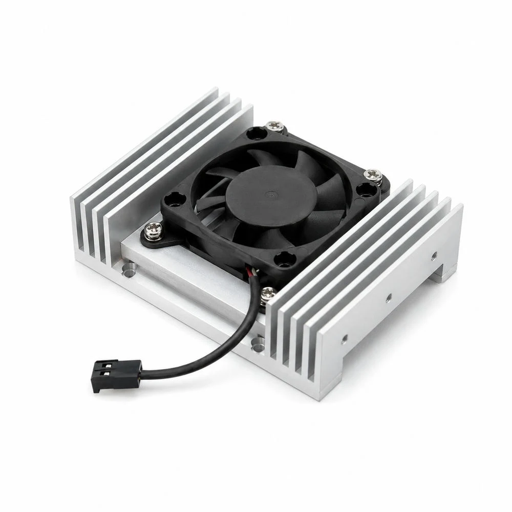
CNC 히트싱크는 AI 서버 전력 모듈에서 단순히 열을 식히는 알루미늄 부품이 아닙니다. GPU와 AI 가속기 주변 전력 변환부, VRM, PMIC, 고전류 DC-DC 모듈은 제한된 보드 면적 안에서 높은 열밀도를 만들고, 그 열은 패키지 접촉면, TIM, 베이스 플레이트, 핀 유로, 서버 팬 또는 액체 냉각 경로를 거쳐 빠져나가야 합니다.
AI 서버는 랙 단위 전력 밀도가 높고 부품 간격이 좁기 때문에 방열판의 크기만 키우는 방식으로는 열관리를 해결하기 어렵습니다. 열원 위치, 장착 홀, 베이스 평탄도, 핀 간격, 압력손실, 표면처리, 조립 압력, 세척 품질이 모두 맞아야 실제 운전 조건에서 온도 안정성이 확보됩니다.
고열밀도 전력 모듈의 열경로 정의
AI 서버 전력 모듈의 열관리는 발열체에서 시작됩니다. 같은 소비전력을 갖는 부품이라도 열이 넓게 퍼지는지, 작은 면적에 집중되는지에 따라 히트싱크 설계가 달라집니다. 전력 변환부와 AI 가속기 주변은 순간 부하 변동이 크고, 특정 소자에 열이 집중되는 경우가 많아 단순 평균 온도보다 hotspot 위치를 먼저 해석해야 합니다.
열은 가장 짧은 경로로만 이동하지 않습니다. 발열체와 베이스 사이의 접촉 상태, 베이스 내부의 열확산 능력, 핀을 통과하는 공기 유량, 서버 섀시 내부의 압력 분포에 따라 실제 열경로가 바뀝니다. 따라서 CNC 히트싱크는 칩 위에 올리는 부품이 아니라 서버 전체 공기 흐름 안에서 작동하는 열전달 구조로 설계해야 합니다.
초기 설계에서는 열원 면적, 허용 온도 상승, 주변 유속, 설치 방향, 팬 정압, 모듈 높이 제한, 체결 위치를 함께 놓고 검토해야 합니다. 이 단계에서 베이스 두께와 핀 형상을 잘못 잡으면 후속 가공 정밀도를 높여도 열성능 한계를 보완하기 어렵습니다.
베이스 평탄도와 열접촉 저항
히트싱크의 가장 중요한 면은 발열체와 맞닿는 베이스입니다. 베이스면이 충분히 평탄하지 않으면 TIM이 공극을 메우기 위해 두꺼워지고, 열은 알루미늄보다 열전도율이 낮은 계면층을 더 길게 통과해야 합니다. 작은 가공 흔적과 국부적인 휨도 실제 접촉면에서는 열저항 증가로 이어질 수 있습니다.
AI 서버 전력 모듈은 볼트 체결이나 스프링 로드로 방열판을 누르는 경우가 많습니다. 체결 압력이 너무 낮으면 접촉 열저항이 커지고, 너무 높으면 패키지나 PCB가 휘어질 수 있습니다. CNC 가공 단계에서는 장착 홀 위치도, 카운터보어 깊이, 베이스 두께 균일성, 체결면 직각도를 함께 관리해야 합니다.
표면 조도는 낮을수록 무조건 유리하다고 단정하기 어렵습니다. TIM 종류와 도포 두께, 체결 압력, 표면 방향성에 따라 적정 거칠기 범위가 달라질 수 있습니다. 접촉면은 열전달면이고 외부 핀 표면은 대류면이므로 두 영역의 표면처리 기준을 분리하는 것이 합리적입니다.
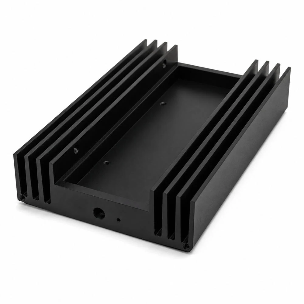
핀 형상과 서버 풍량의 균형
방열핀은 표면적을 늘리는 구조이지만, 핀을 촘촘하게 만들수록 공기가 지나갈 공간은 줄어듭니다. AI 서버처럼 팬이 강하게 공기를 밀어 넣는 환경에서는 핀 밀도를 높일 수 있지만, 압력손실이 과도해지면 실제 유량이 줄어 열전달 성능이 오히려 떨어질 수 있습니다.
핀 높이, 두께, 피치, 유로 길이, 슬롯 바닥 형상은 서버 팬의 정압과 덕트 구조를 기준으로 결정해야 합니다. 특히 1U, 2U 서버처럼 높이 제한이 큰 장비에서는 높은 핀보다 낮고 길게 이어지는 유로가 유리할 수 있으며, 측면 흡기나 전후면 관통 유동 구조에서는 핀 방향 자체가 설계 기준이 됩니다.
CNC 가공 관점에서는 얇은 핀의 휨, 공구 떨림, 슬롯 바닥 잔류 칩, 핀 끝단 버가 핵심 관리 항목입니다. 열성능이 좋은 형상이라도 제조 과정에서 핀이 변형되거나 유로가 막히면 실제 냉각 효율은 낮아집니다.
AI 서버 전력 모듈용 CNC 히트싱크 설계 매트릭스
셀 위에 커서를 올리면 설계 판단 기준을 확인할 수 있습니다. 수치는 특정 제품 성능값이 아니라 열관리 검토 순서를 정리하기 위한 기술 기준입니다.
| 설계 변수 | 열관리 역할 | CNC 가공 기준 | 검사 항목 | 품질 리스크 | 판단 기준 |
|---|---|---|---|---|---|
| 베이스 플레이트 | 열원에서 받은 열을 히트싱크 전체로 확산합니다. | 평탄도, 두께 균일성, 면 조도, 체결면 직각도 | 평탄도, Ra/Rz, 체결 후 접촉 흔적, 기준면 버 | 국부 공극, TIM 두께 증가, 열접촉 저항 상승 | 발열체 크기와 체결 압력을 기준으로 베이스 두께와 면 품질을 결정합니다. |
| 핀 높이와 간격 | 대류 표면적을 늘리고 공기와 열교환합니다. | 얇은 핀 휨, 공구 떨림, 슬롯 깊이, 핀 끝단 버 | 핀 두께, 피치, 평행도, 슬롯 바닥 잔류 칩 | 압력손실 증가, 먼지 축적, 핀 파손, 유량 편차 | 서버 팬 정압과 유로 방향을 기준으로 조밀도와 높이를 조정합니다. |
| 핫스팟 확산 | AI 가속기와 전력 모듈의 국부 발열을 넓은 면적으로 분산합니다. | 열원 하부 두께, 열확산 홈, 히트파이프 홈 정밀도 | 접촉면 위치도, 홈 깊이, 압입면 거칠기, 단차 | 열집중, 접합부 피로, 모듈별 온도 편차 | 발열 중심과 핀 배열 중심이 어긋나지 않도록 열경로를 배치합니다. |
| TIM과 체결 압력 | 미세 공극을 채우고 발열체와 베이스 사이 열저항을 낮춥니다. | 장착 홀 위치도, 카운터보어 깊이, 체결면 평탄도 | 홀 위치도, 볼트 안착면, 체결 후 평면 변형 | TIM 펌프아웃, 압력 불균일, 모듈 휨 | 볼트 패턴과 베이스 강성을 함께 설계해 압력을 균일화합니다. |
| 표면처리와 세척 | 부식 억제, 표면 방사 특성, 전장 환경 내 오염 관리를 담당합니다. | 아노다이징 전 표면 균일성, 접촉면 마스킹, 세척성 | 막 두께, 표면 얼룩, 잔류 칩, 접촉면 산화막 관리 | 접촉 열저항 증가, 이물 혼입, 절연/접지 조건 불안정 | 접촉면과 외부 방열면을 구분해 표면처리 범위를 정합니다. |
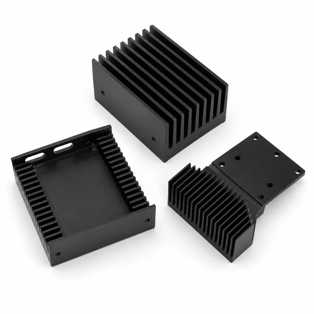
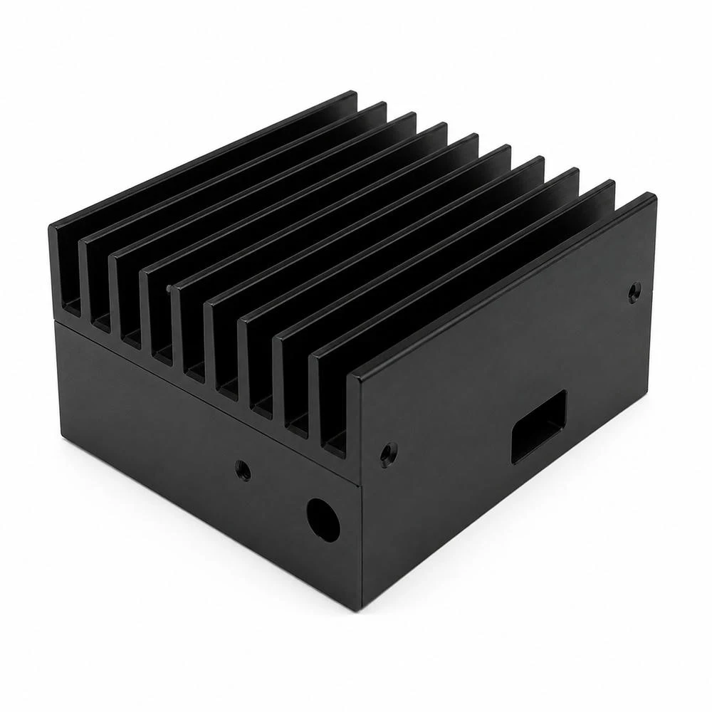
전력 모듈 하우징과 장착 기준면
AI 서버용 히트싱크는 단독 방열판으로만 쓰이지 않고 전력 모듈 하우징, 브라켓, 커버, 고정 프레임의 일부가 되는 경우가 많습니다. 이때 방열 기능과 기구 고정 기능이 같은 부품에 들어가므로 기준면 선택이 중요합니다. 베이스 접촉면, 외곽 장착면, 홀 위치, 측면 체결면이 서로 다른 품질 기준을 갖습니다.
하우징 일체형 구조에서는 열원 접촉면의 평탄도와 외곽 체결면의 위치도를 동시에 맞춰야 합니다. 장착 홀 위치가 어긋나면 체결 압력이 불균일해지고, 베이스면이 미세하게 비틀릴 수 있습니다. 열접촉 저항은 표면 조도만의 문제가 아니라 기구 조립 오차와 함께 커질 수 있습니다.
흑색 아노다이징처럼 표면처리가 적용되는 경우에는 접촉면 마스킹, 막 두께, 홀 내부 잔류 이물, 체결면의 코팅 상태를 분리해 관리해야 합니다. 외부 방열면에서는 표면 보호와 방사 특성이 중요하지만, 발열체 접촉면에서는 코팅층이 열저항과 접촉 안정성에 영향을 줄 수 있습니다.
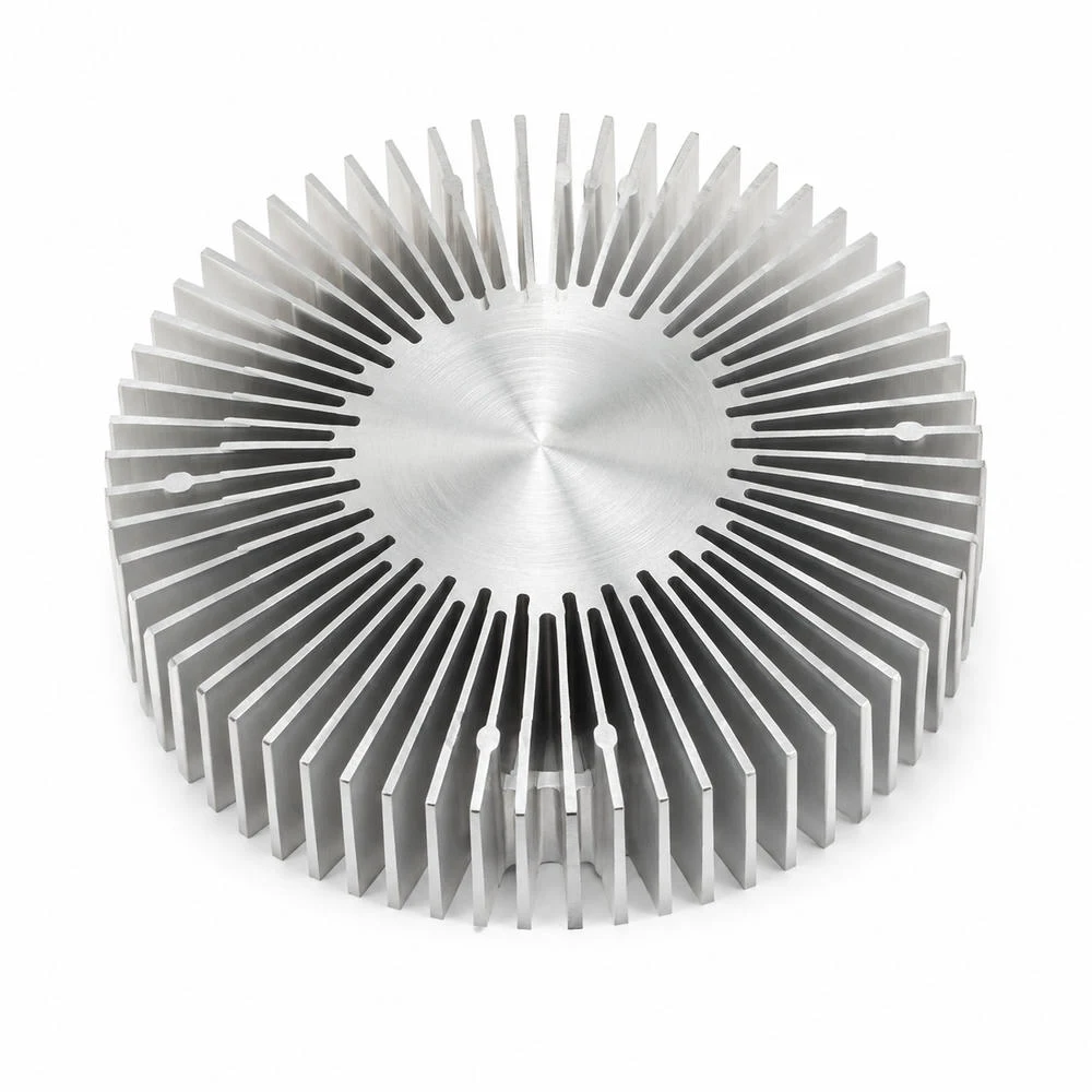
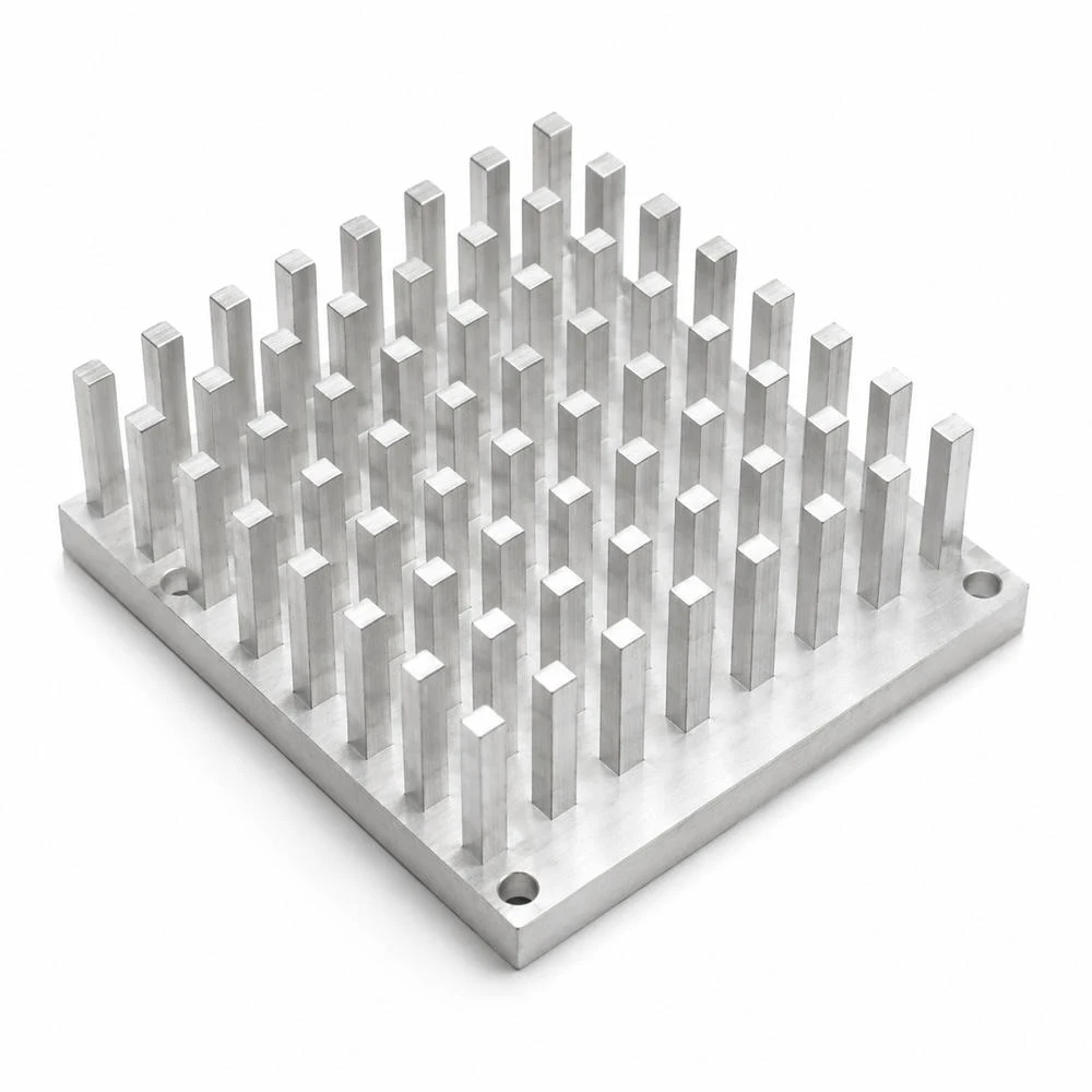
핀핀 배열과 다방향 열확산
핀핀 배열은 공기 흐름 방향이 고정되지 않거나 국부 발열을 여러 방향으로 분산해야 하는 구조에서 검토할 수 있습니다. 일반적인 직선 핀은 특정 방향 유동에 유리하지만, 핀핀 구조는 난류 혼합과 다방향 유동 대응에 장점이 있습니다. 다만 같은 면적 안에서 가공 시간이 늘고, 핀 사이 세척과 버 제거가 어려워질 수 있습니다.
AI 서버 보드에서는 전력 모듈 주변에 커넥터, 케이블, 메모리, 인덕터, 쉴드 캔이 함께 배치됩니다. 공기가 항상 이상적인 한 방향으로 흐르지 않기 때문에 열확산 구조는 장비 레이아웃과 함께 설계해야 합니다. 베이스 중심에서 핀 배열 전체로 열을 넓히는 능력이 부족하면 일부 핀만 뜨거워지고 나머지 표면적은 충분히 활용되지 못합니다.
핀핀 구조의 품질 기준은 핀 높이 균일성, 뿌리부 R, 핀 간격, 상단 모서리 버, 베이스 평탄도입니다. 핀 수가 많을수록 단일 핀의 작은 변형도 공기 유로와 세척성에 영향을 줄 수 있으므로 가공 후 디버링과 세정 조건까지 설계 기준에 포함해야 합니다.
AI 서버 전력 모듈의 열경로 설계 순서
고발열 모듈의 열관리는 열원에서 시작해 접촉면, 베이스 열확산, 핀 유로, 랙 공기 흐름 또는 액체 냉각 경로까지 이어지는 연속 조건으로 보아야 합니다. 아래 흐름은 CNC 히트싱크 설계에서 우선순위를 정하는 기준입니다.
표면처리와 전장 환경의 신뢰성
데이터센터 장비는 장시간 연속 운전되고, 먼지와 미세 입자, 냉각풍, 진동, 반복 열사이클에 노출됩니다. 히트싱크 표면처리는 단순 외관이 아니라 부식 억제, 오염 관리, 방사 특성, 절연 또는 접지 조건과 연결됩니다. 흑색 아노다이징은 외부 방열면에서 유리할 수 있지만 접촉면에서는 별도 관리가 필요합니다.
아노다이징 전 표면의 절삭흔, 얼룩, 세척 상태가 균일하지 않으면 막 두께와 외관이 흔들릴 수 있습니다. 핀 사이 깊은 슬롯에 칩이나 절삭유가 남으면 열전달뿐 아니라 전장 환경의 오염 리스크가 됩니다. 고밀도 핀 구조에서는 세척성과 배수성까지 제조 기준에 포함해야 합니다.
표면처리 후에는 장착 홀, 나사부, 접촉면, 접지면의 상태를 구분해 검사해야 합니다. 전력 모듈 주변 부품은 열만이 아니라 전기적 안정성도 중요하므로 절연이 필요한 면과 도통이 필요한 면을 명확히 분리해야 합니다.
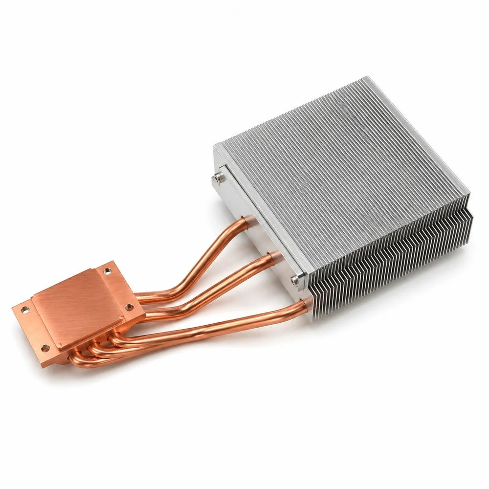
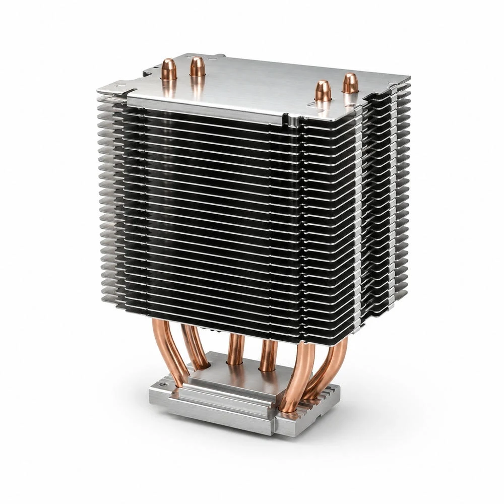
히트파이프와 콜드플레이트로 확장되는 열경로
열밀도가 더 높아지면 알루미늄 핀만으로는 열을 충분히 넓히기 어렵습니다. 이때 히트파이프, 베이퍼 챔버, 액체 냉각 콜드플레이트가 열경로를 확장합니다. CNC 가공은 이러한 구조에서 히트파이프 홈, 압입면, 접촉면, 브레이징 또는 접합 기준면, 유로와 씰링면을 정밀하게 만드는 역할을 합니다.
히트파이프는 국부 열원에서 떨어진 핀 영역까지 열을 이동시키는 데 유리합니다. 하지만 파이프와 베이스 사이의 접촉 품질이 불안정하면 열이 충분히 전달되지 않습니다. 홈 깊이, 파이프 안착면, 압입 압력, 접합면 상태, 클램프 구조가 함께 맞아야 열경로가 안정됩니다.
액체 냉각 구조로 넘어가면 열전달 성능뿐 아니라 누설, 압력손실, 유로 막힘, 부식, 이종금속 접촉도 검토해야 합니다. CNC 히트싱크 설계는 공랭 방열판에서 끝나는 것이 아니라 고발열 장비의 냉각 구조 전체로 확장되는 기반 기술입니다.
랙 단위 열관리와 맞춤형 구조 설계
AI 서버의 열관리는 단일 부품의 온도만 낮추는 문제가 아닙니다. 랙 내부의 흡기와 배기, 서버 간 간격, 팬 속도, 덕트 설계, 전력 모듈 배치, 케이블 경로가 모두 히트싱크 성능에 영향을 줍니다. 따라서 맞춤형 히트싱크는 장비 내부에서 실제로 공기가 흐르는 방향과 유지보수 조건을 함께 반영해야 합니다.
전력 모듈 주변은 고전류 배선과 커넥터가 많아 기구 간섭이 쉽게 발생합니다. 방열핀의 높이를 키우면 열성능은 좋아질 수 있지만 케이블, 커넥터, 커버, 팬 덕트와 충돌할 수 있습니다. 반대로 높이를 낮추면 베이스 두께, 핀 밀도, 히트파이프 보조 구조가 더 중요해집니다.
AI 서버 전력 모듈용 CNC 히트싱크는 베이스 접촉면, 장착 홀, 핀 유로, 표면처리, 세척성, 확장 냉각 구조를 하나의 설계 기준으로 연결해야 합니다. 열관리 기준은 부품 단독 성능이 아니라 조립 후 서버 운전 조건에서 안정적으로 반복되는지로 판단해야 합니다.
CNC 히트싱크 품질 기준의 핵심
AI 서버 전력 모듈의 방열 설계는 열저항을 한 번에 줄이는 단일 해법보다 열경로의 병목을 하나씩 낮추는 방식으로 접근해야 합니다. 발열체와 베이스 사이의 접촉 저항, 베이스 내부의 확산 저항, 핀과 공기 사이의 대류 저항, 서버 유로의 압력손실이 모두 연결되어 전체 온도 상승을 만듭니다.
따라서 CNC 히트싱크의 품질 기준은 치수 공차만으로 충분하지 않습니다. 베이스 평탄도, 표면 조도, TIM 압착 조건, 장착 홀 위치도, 핀 피치와 평행도, 버 제거, 표면처리, 세척 품질, 히트파이프 또는 콜드플레이트 결합면을 같은 기준 안에서 검토해야 합니다.
CNC 히트싱크는 AI 서버 전력 모듈의 고발열을 장비 구조 안에서 안정적으로 분산시키는 열관리 부품이며, 설계와 가공과 검사가 하나의 열경로 기준으로 연결될 때 실제 운전 조건에서 의미 있는 성능을 냅니다.
English Technical Overview
CNC Heat Sink Design for AI Server Power Modules
A CNC heat sink for an AI server power module should not be understood as a simple aluminum block with fins. It is a precision thermal component that connects a high-density heat source to a controlled cooling path. The heat must travel from the power device or accelerator package through the thermal interface material, into the base plate, across the heat-spreading body, through the fins, and finally into the server airflow or liquid-cooling loop.
AI servers create a demanding thermal environment because power density is concentrated in a small mechanical envelope. GPUs, AI accelerators, voltage regulator modules, PMICs, and high-current DC-DC converters can produce strong local hotspots. The heat sink must fit around connectors, cables, shields, ducts, fans, and structural hardware while still maintaining stable contact pressure and predictable airflow.
The engineering task is therefore not only to increase surface area. A good design must reduce the dominant thermal bottlenecks: contact resistance at the module interface, spreading resistance in the base, convection resistance at the fin field, and pressure loss through the server airflow path. CNC machining becomes important because it controls the surfaces, holes, grooves, edge quality, and assembly datums that determine whether the design works under real operating conditions.
Heat Source Mapping and Thermal Path Planning
The first design step is to define the heat source. Average power is not enough. The location, size, transient load behavior, and allowable junction or case temperature should be considered together. A compact power module can produce a localized thermal load that reaches the spreading limit of the base before the fin field becomes the main limitation.
Once the heat-source position is known, the thermal path can be planned. The base plate must receive heat with minimum contact resistance, spread it laterally, and deliver it into the fin or heat-pipe region. If the heat source is not aligned with the effective spreading region, part of the fin area may remain underused while the module-side contact area stays hot.
In dense server systems, the heat sink also operates inside a larger air-management structure. The same fin geometry can perform differently depending on fan static pressure, duct leakage, rack airflow direction, and downstream obstruction. This is why the heat sink should be designed with the server airflow path in mind, not as an isolated part.
Base Flatness, TIM Thickness, and Contact Resistance
The base plate is the primary functional surface of the heat sink. If the base is not flat enough, the thermal interface material must compensate for the gap. This increases bond-line thickness and can raise the effective contact resistance. A smooth-looking base is not automatically a good thermal contact surface; flatness, surface texture, waviness, local tool marks, and clamp behavior all matter.
Thermal interface materials fill microscopic voids, but they are not a substitute for poor mechanical contact. The correct TIM thickness depends on material type, surface finish, clamping load, package stiffness, and long-term pump-out behavior. Mounting-hole position, counterbore depth, bearing-face flatness, and bolt pattern symmetry help determine whether pressure is distributed evenly.
For CNC machining, this means that the thermal contact face should be treated separately from external cooling surfaces. A coating that is useful on the exposed fin field may not be appropriate on the direct contact surface unless the thermal and electrical requirements are clearly defined. Contact faces, grounding faces, insulated faces, and cosmetic faces should not be controlled by one generic surface rule.
CNC Heat Sink Design Matrix for AI Server Power Modules
This matrix mirrors the Korean technical table for international B2B readers. Hover over each cell to review why each item matters in high-density server thermal design.
| Design Variable | Thermal Role | CNC Control Point | Inspection Item | Quality Risk | Decision Logic |
|---|---|---|---|---|---|
| Base plate | Spreads heat from the module into the heat sink body. | Flatness, thickness stability, surface roughness, mounting-face squareness | Flatness, Ra/Rz, contact trace, edge burr | Air gaps, excessive TIM thickness, higher contact resistance | Define base thickness and surface quality from heat-source size and clamp pressure. |
| Fin height and pitch | Expands convective surface area and guides air through the heat sink. | Thin-fin deflection, tool chatter, slot depth, fin-edge burrs | Fin thickness, pitch, parallelism, slot-bottom cleanliness | Pressure drop, dust accumulation, fin damage, airflow imbalance | Match fin density and height to server fan static pressure and duct direction. |
| Hotspot spreading | Distributes local module heat into a wider cooling area. | Base thickness, heat-pipe groove, vapor-chamber or insert seat | Contact position, groove depth, pressed-seat finish, step height | Hotspot retention, joint fatigue, module temperature imbalance | Align heat-source centers with the spreading path and fin field. |
| TIM and clamp load | Fills microscopic voids between the module and base surface. | Mounting-hole position, counterbore depth, bearing-surface flatness | Hole position, bolt seat, deformation after fastening | TIM pump-out, uneven pressure, package or board bending | Design bolt pattern and base stiffness together to stabilize contact pressure. |
| Surface treatment | Controls corrosion resistance, appearance, contamination, and exposed surfaces. | Pre-anodizing finish, contact-surface masking, cleaning quality | Coating thickness, stains, chip residue, contact-surface condition | Higher contact resistance, contamination, unstable grounding or insulation | Separate the thermal contact face from the external heat-radiating surface. |
Fin Geometry, Airflow, and Pressure Drop
Fins increase surface area, but they also create flow resistance. A very dense fin field can look efficient from a surface-area perspective while restricting actual airflow. In server systems with high-pressure fans, dense fins may be practical, but the relationship between fin pitch, fin height, flow direction, and pressure drop must be reviewed with the fan and duct system.
Thin fins create additional manufacturing concerns. Tool chatter, fin deflection, slot-bottom chips, edge burrs, and inconsistent fin spacing can reduce the real thermal performance. In high-volume or high-reliability assemblies, cleaning and deburring become part of the thermal design because blocked channels or loose particles can create reliability risks.
Different fin styles serve different airflow conditions. Straight fins are efficient when the flow direction is controlled. Pin fins can support more multidirectional flow and local mixing. Radial fin fields can be useful when air approaches from multiple directions or when a circular spreading pattern is desired. None of these structures is universally superior; the best choice depends on heat-source layout, airflow path, mechanical envelope, and manufacturability.
Heat Pipes, Vapor Chambers, and Cold Plate Transition
As heat density increases, a conventional aluminum fin heat sink may need additional spreading technology. Heat pipes, vapor chambers, and liquid cold plates extend the thermal path from a concentrated source to a larger heat rejection area. CNC machining supports these architectures by creating accurate grooves, seats, contact planes, sealing surfaces, and mounting structures.
A heat pipe is only effective when its interface to the base is controlled. Groove depth, pressed contact, soldering or bonding quality, clamping method, and local flatness all affect how heat enters the pipe. A vapor chamber or cold plate introduces additional concerns such as sealing, coolant compatibility, pressure drop, corrosion, and leakage control.
For AI server power modules, the boundary between air cooling and liquid-assisted cooling is becoming more important. A CNC heat sink may function as a standalone air-cooled component, a heat-pipe base, a vapor-chamber carrier, or a cold-plate interface. The machining standard should be able to support that transition.
Surface Treatment and Electrical Environment
Surface treatment is not only an appearance decision. Anodizing, black finish, masking, cleaning, and deburring can affect corrosion resistance, contamination, radiation behavior, grounding, insulation, and contact resistance. For server components, the final surface condition must be compatible with the thermal path and with the electrical environment around the module.
Black anodizing may be useful for external surfaces, but direct thermal contact surfaces need careful review. Film thickness, masking accuracy, post-treatment cleanliness, and edge coverage should be controlled. Holes, threads, and counterbores should also be checked because coating buildup or residue can affect assembly pressure and alignment.
Cleaning is especially important for dense fin structures. Chips and cutting fluid trapped between fins can affect airflow and create contamination risks in electronics. A heat sink intended for AI server use should therefore be evaluated for cleanability, not only for machining precision.
Practical Quality Standard for AI Server Heat Sinks
The practical quality standard for a CNC heat sink begins with the thermal function. The first inspection priority is the contact base: flatness, surface texture, burr condition, and mounting-hole relationship. The second priority is heat spreading: base thickness, local hotspot alignment, heat-pipe groove quality, and the relationship between heat-source position and fin field. The third priority is air or coolant path: fin pitch, fin parallelism, pressure-drop sensitivity, cleaning access, and surface condition.
This approach prevents the design from becoming a simple list of dimensions. It connects machining accuracy to thermal behavior. A heat sink can pass dimensional inspection but still perform poorly if contact pressure is uneven, if the TIM bond line is too thick, if fins are too dense for the server fan, or if the heat pipe interface is unstable.
A high-quality CNC heat sink for AI server power modules is therefore defined by the disciplined connection between thermal path, mechanical datum, contact surface, airflow path, surface treatment, and inspection method. When these elements are planned together, the part can support stable thermal management in dense data-center equipment and high-performance power electronics.
추가 정보
검색엔진용 요약
CNC 히트싱크는 AI 서버 전력 모듈의 열을 칩 패키지에서 베이스, 열전달층, 방열핀, 공기 또는 냉각수 경로로 안정적으로 이동시키기 위한 정밀가공 부품입니다. 베이스 평탄도, 열접촉 저항, 핀 형상, 압력손실, 표면처리, 장착 홀 위치가 함께 관리되어야 서버 장비의 열관리 기준이 명확해집니다.
핵심 포인트 정리
- AI 서버 전력 모듈은 국부 열밀도가 높아 열원 위치와 베이스 열확산 경로를 먼저 검토해야 합니다.
- 히트싱크 베이스면은 평탄도, 면 조도, 체결 압력, TIM 두께가 함께 맞아야 접촉 열저항을 낮출 수 있습니다.
- 방열핀은 표면적만 늘리는 구조가 아니라 서버 팬 풍량과 압력손실을 함께 고려해야 하는 유로 부품입니다.
- 고밀도 핀, 핀핀, 방사형 핀, 채널형 핀은 냉각 방향과 설치 공간에 따라 장단점이 달라집니다.
- 흑색 아노다이징, 세척, 버 제거, 모서리 품질은 열성능과 조립 신뢰성 모두에 영향을 줍니다.
- 히트파이프, 베이퍼 챔버, 콜드플레이트는 공랭 히트싱크의 열확산 한계를 보완하는 확장 구조입니다.
FAQ
AI 서버에는 왜 맞춤형 CNC 히트싱크가 필요합니까?
AI 서버는 GPU, AI 가속기, 전력 모듈, VRM 주변에서 국부 발열이 집중됩니다. 표준 방열판만으로는 장착 공간, 홀 위치, 공기 흐름, 열원 분포를 모두 맞추기 어렵기 때문에 장비 구조에 맞춘 CNC 히트싱크 설계가 필요합니다.
히트싱크 베이스 평탄도는 왜 중요합니까?
베이스면은 발열체와 직접 열을 주고받는 접촉면입니다. 평탄도가 부족하면 TIM 두께가 불균일해지고, 국부 공극이 생기면서 열접촉 저항이 커질 수 있습니다.
방열핀은 많을수록 항상 유리합니까?
핀 수가 늘면 표면적은 증가하지만 유로가 좁아져 압력손실도 커질 수 있습니다. 서버 팬의 정압과 풍량, 먼지 관리, 세척성까지 함께 고려해야 합니다.
흑색 아노다이징은 열관리에 도움이 됩니까?
흑색 아노다이징은 표면 보호와 방사 특성 측면에서 유리할 수 있지만, 접촉면에서는 막 두께와 표면 상태가 열저항에 영향을 줄 수 있습니다. 접촉 베이스면과 외부 방열면을 구분해 관리하는 것이 중요합니다.
히트파이프와 CNC 히트싱크는 어떻게 연결됩니까?
히트파이프는 국부 열원을 넓은 방열핀 영역으로 이동시키는 열전달 경로입니다. CNC 가공 베이스는 히트파이프 홈, 압입면, 접촉면, 체결면을 정밀하게 만들기 위해 사용됩니다.
데이터센터용 히트싱크에서 검사 기준은 무엇입니까?
베이스 평탄도, 표면 조도, 핀 두께와 간격, 장착 홀 위치도, 버 제거, 표면처리 상태, 세척 품질, 체결 후 접촉 안정성을 함께 봐야 합니다. 열성능은 가공 치수와 조립 조건이 동시에 맞을 때 안정됩니다.
관련 주제 확장 설명
열접촉 저항과 TIM 관리
TIM은 베이스와 발열체 사이의 미세 공극을 채우지만, 두께가 지나치게 늘어나면 열저항이 커질 수 있습니다. 베이스면 가공 품질과 체결 압력은 TIM 성능을 실제 조립 조건에서 안정화하는 핵심 요소입니다.
핀 구조와 서버 풍량
데이터센터 장비는 제한된 랙 공간 안에서 높은 풍량과 낮은 압력손실을 동시에 요구합니다. 핀 높이, 간격, 두께, 배열 방향은 팬과 덕트 구조를 함께 보고 결정해야 합니다.
공랭과 액체 냉각의 경계
열밀도가 높아질수록 히트싱크는 히트파이프, 베이퍼 챔버, 콜드플레이트와 결합됩니다. CNC 가공은 이러한 구조의 접촉면, 유로, 체결면, 씰링면을 정밀하게 형성하는 기반 공정입니다.
내부 링크
제조 기술 관련 글은 인사이트에서 확인할 수 있으며, CNC 히트싱크와 알루미늄 방열판 가공은 cnc정밀가공부품 항목과 직접 연결됩니다. 장착 브라켓과 체결 구조는 구조연결용 부품, 판재 기반 방열 구조는 정밀프레스가공 부품 관점에서도 함께 볼 수 있습니다.
전장 모듈 조립과 배선 환경은 케이블와이어 하네스, 전기적 접촉 안정성은 전기접점, 금속 접합과 열전달 구조는 브레이징 및 금속접합소재와도 연결됩니다.