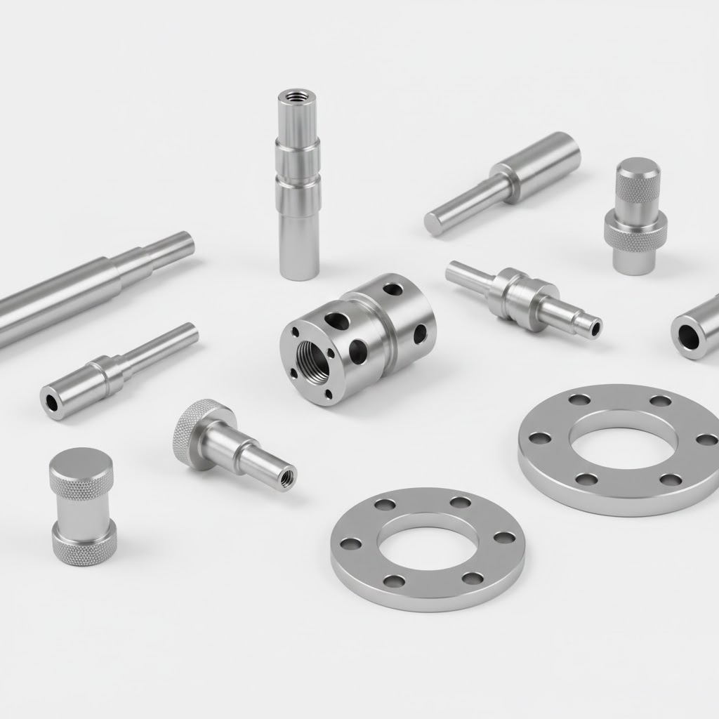
CNC 선삭가공과 CNC 밀링가공
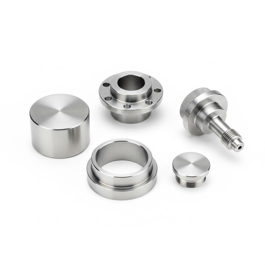
CNC 가공의 대표적인 두 공정인 선삭가공과 밀링가공은 각각 독특한 강점을 가지고 있어 부품의 형상과 요구 사항에 따라 선택적으로 사용됩니다.
CNC 가공의 기본 개념
CNC(Computer Numerical Control) 가공은 컴퓨터로 제어되는 공작기계를 통해 고정밀 부품을 생산하는 기술입니다. 절삭 가공 중 가장 널리 사용되는 선삭과 밀링은 모두 재료 제거 방식이지만, 공작물과 공구의 상대 운동 방식이 근본적으로 다릅니다. 이 차이가 부품 설계 단계부터 공정 계획까지 모든 결정에 영향을 미칩니다.
CNC 선삭가공(Turning)
선삭가공은 공작물을 고속 회전시키고 고정된 단일점 절삭 공구를 직선 이동시켜 외경, 내경, 단면, 나사 등을 가공하는 공정입니다. 주로 회전체 부품 생산에 최적화되어 있으며, 높은 생산성과 우수한 표면 품질을 제공합니다.
주요 특징 및 프로세스
- 공작물이 주축(spindle)에 의해 회전하고, 공구는 X축(반경 방향)과 Z축(축 방향)을 따라 이동
- 기본 2축에서 다축(live tooling, Y축, B축 추가)으로 확장 가능
- 가공 순서: 외경 roughing → finishing → 내경 보링 → 그루빙 → 나사산 가공 → 절단(part-off)
핵심 프로세스
- 주축 회전수(RPM): 재료와 공구에 따라 500~8000 RPM 이상
- 이송량(feed rate): 0.05~0.5 mm/rev
- 절삭 깊이(depth of cut): roughing 시 2~5 mm, finishing 시 0.1~0.5 mm
- 진동 억제와 열 변형 최소화를 위한 적응 제어 시스템
응용
- 라이브 툴링 적용 시 밀링, 드릴링, 탭핑 동시 수행 → 턴-밀 복합 가공
- 고속 선삭(HSK, CBN 인서트 사용)으로 티타늄 합금 가공 시간 40% 이상 단축
- 초음파 진동 보조 선삭으로 난삭재(인코넬, 하스텔로이) 칩 브레이킹 향상
적용 분야
항공우주 터빈 샤프트, 자동차 크랭크샤프트, 유압 실린더 로드, 의료용 임플란트 로드 등
CNC 밀링가공(Milling)
밀링가공은 다날 공구(엔드밀)를 고속 회전시키고 공작물을 X, Y, Z축(필요 시 추가 회전축)으로 이동시켜 평면, 포켓, 곡면, 슬롯 등을 가공하는 공정입니다. 복잡한 3D 형상과 비회전체 부품에 강점을 보입니다.
주요 특징 및 프로세스
- 공구가 회전하고 공작물이 테이블 위에서 이동
- 3축에서 5축 동시 제어까지 확장 가능
- 가공 순서: 면취 → 포켓 roughing → 컨투어 finishing → 홀 가공 → 탭핑
핵심 프로세스
- 주축 회전수: 8000~30000 RPM (고속 가공 시 40000 RPM 이상)
- 이송 속도: 1000~10000 mm/min
- 스텝오버(stepover): roughing 50~70%, finishing 5~10%
- 트로코이달 경로와 적응형 이송 제어로 공구 수명 2~3배 연장 가능
응용
- 5축 동시 가공으로 임펠러, 터빈 블레이드, 금형 코어/캐비티 단일 셋업 완성
- 고속 가공(HSM) 전략으로 얇은 벽 구조물 변형 최소화
- 하이브리드 공정(밀링 + 레이저 텍스처링, 밀링 + EDM)으로 초경질 재료 대응
적용 분야
항공기 구조물, 자동차 다이 캐스팅 금형, 의료기기 하우징, 반도체 장비 프레임 등
선삭가공 밀링가공
| 항목 | CNC 선삭가공 (Turning) | CNC 밀링가공 (Milling) |
|---|---|---|
| 상대 운동 | 공작물 회전 + 공구 직선 이동 | 공구 회전 + 공작물 다축 이동 |
| 적합 형상 | 회전 대칭 부품 (원통, 원추, 샤프트) | 비대칭, 복잡 3D 형상 (포켓, 곡면, 슬롯) |
| 생산성 | 대량 회전체 부품에서 매우 높음 | 복잡 형상에서 우수하나 셋업 시간 상대적으로 길음 |
| 표면 품질 | 원통도, 동심도 우수 | 평탄도, 윤곽 정밀도 우수 |
| 공구 종류 | 단일점 공구 (터닝 인서트) | 다날 공구 (엔드밀, 볼밀, 페이스밀) |
| 축 구성 | 기본 2~4축, 최대 9축 (복합 선반) | 기본 3축, 최대 5축 이상 동시 제어 |
| 칩 관리 | 연속 칩 발생, 칩 브레이커 중요 | 단속 칩 발생, 칩 배출 경로 설계 중요 |
| 재료 제거율(MRR) | 일반적으로 높음 | 고속 가공 시 동등 또는 상회 |
| 한계 | 비회전 형상 가공 어려움 | 대형 회전체 부품 가공 시 비효율적 |
- 회전 대칭도가 80% 이상인 부품 → 선삭 중심 공정
- 복잡한 포켓, 다면 가공 필요 → 밀링 중심 공정
- 최적 솔루션: 턴-밀 복합 머신(Multitasking Machine) 활용 → 단일 셋업으로 선삭 + 밀링 완성, 공차 누적 최소화, 리드타임 30~50% 단축
제조 트렌드는 점점 더 복합화되고 있으며, 5축 이상의 턴-밀 복합 기계가 고정밀 부품 생산의 표준으로 자리 잡고 있습니다.
Turning and milling, the two representative processes in CNC machining, each offer distinct strengths and are selectively applied depending on part geometry and functional requirements.
CNC Machining: Fundamental Concept
CNC (Computer Numerical Control) machining is a manufacturing technology that produces high-precision components using computer-controlled machine tools. Among subtractive manufacturing processes, turning and milling are the most widely used. Although both remove material by cutting, the relative motion between the workpiece and the cutting tool differs fundamentally. This difference influences every decision, from part design to process planning.
CNC Turning
Turning is a machining process in which the workpiece rotates at high speed while a fixed single-point cutting tool moves linearly to machine outer diameters, inner diameters, faces, and threads. It is optimized for rotationally symmetric components and provides high productivity with excellent surface finish.
Key Characteristics and Process Flow
The workpiece rotates on the spindle, while the tool moves along the X-axis (radial direction) and Z-axis (axial direction)
Expandable from basic 2-axis configurations to multi-axis systems with live tooling, Y-axis, and B-axis
Typical process sequence:
OD roughing → finishing → internal boring → grooving → threading → part-off
Core Process Parameters
Spindle speed (RPM): typically 500–8,000 RPM or higher depending on material and tooling
Feed rate: 0.05–0.5 mm/rev
Depth of cut:
Roughing: 2–5 mm
Finishing: 0.1–0.5 mm
Adaptive control systems are used to suppress vibration and minimize thermal deformation
Applications and Advanced Techniques
Turn-mill combined machining with live tooling enables milling, drilling, and tapping in a single setup
High-speed turning using CBN inserts or HSK tooling can reduce titanium alloy machining time by over 40 percent
Ultrasonic vibration-assisted turning improves chip breaking when machining difficult-to-cut materials such as Inconel and Hastelloy
Typical Applications
Aerospace turbine shafts
Automotive crankshafts
Hydraulic cylinder rods
Medical implant rods
CNC Milling
Milling is a machining process in which a multi-point cutting tool (end mill) rotates at high speed while the workpiece moves along the X, Y, and Z axes, with optional additional rotary axes. Milling excels at producing complex 3D geometries and non-rotational components.
Key Characteristics and Process Flow
The cutting tool rotates while the workpiece is positioned and moved on the machine table
Configurations range from 3-axis to full 5-axis simultaneous control
Typical process sequence:
Face milling → pocket roughing → contour finishing → hole machining → tapping
Core Process Parameters
Spindle speed: 8,000–30,000 RPM (over 40,000 RPM for high-speed machining)
Feed rate: 1,000–10,000 mm/min
Stepover:
Roughing: 50–70 percent
Finishing: 5–10 percent
Trochoidal toolpaths and adaptive feed control can extend tool life by two to three times
Applications and Advanced Techniques
Five-axis simultaneous machining enables impellers, turbine blades, and mold cores/cavities to be completed in a single setup
High-speed machining strategies minimize deformation in thin-wall structures
Hybrid processes, such as milling combined with laser texturing or EDM, enable machining of ultra-hard materials
Typical Applications
Aircraft structural components
Automotive die-casting molds
Medical device housings
Semiconductor equipment frames
Comparison of CNC Turning and CNC Milling
| Category | CNC Turning | CNC Milling |
|---|---|---|
| Relative motion | Workpiece rotation + linear tool movement | Tool rotation + multi-axis workpiece movement |
| Suitable geometry | Rotationally symmetric parts (cylinders, cones, shafts) | Asymmetric and complex 3D shapes (pockets, surfaces, slots) |
| Productivity | Extremely high for mass production of rotational parts | High for complex geometries, but with longer setup time |
| Surface quality | Excellent cylindricity and concentricity | Excellent flatness and contour accuracy |
| Tool type | Single-point cutting tools (turning inserts) | Multi-point tools (end mills, ball mills, face mills) |
| Axis configuration | Typically 2–4 axes, up to 9 axes in multitasking lathes | Typically 3 axes, up to 5-axis simultaneous control |
| Chip behavior | Continuous chips; chip breaker design is critical | Discontinuous chips; chip evacuation path is critical |
| Material removal rate (MRR) | Generally high | Comparable or higher with high-speed machining |
| Limitations | Inefficient for non-rotational geometries | Inefficient for large rotational components |
Process Selection Guidelines
Parts with over 80 percent rotational symmetry → Turning-centered process
Parts requiring complex pockets or multi-face machining → Milling-centered process
Optimal solution: Turn-mill multitasking machines
Complete turning and milling in a single setup
Minimize tolerance stack-up
Reduce lead time by 30–50 percent
Manufacturing trends continue to move toward greater process integration, and turn-mill multitasking machines with five or more axes are becoming the standard solution for high-precision component production.