워터펌프 압력 스위치 접점의 개폐 안정성
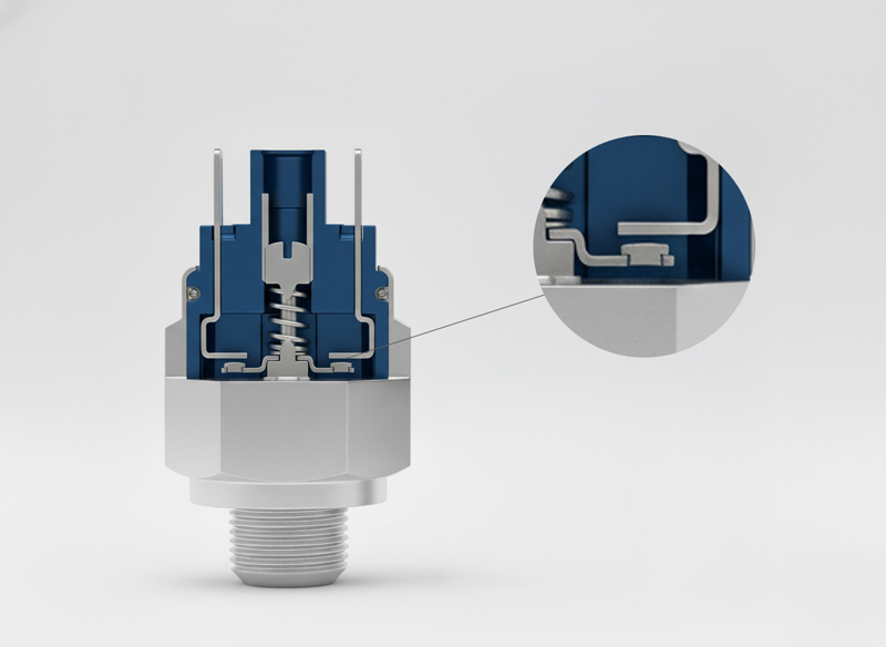
워터펌프 압력 스위치 접점은 수압 변동을 전기적 개폐 신호로 바꾸는 기능 부품입니다. 압력 스위치는 단순히 설정 압력에서 켜지고 꺼지는 장치가 아니라, 다이어프램 또는 피스톤 변위, 스프링 하중, 스냅액션, 접점 간극, 접촉하중, 부하 전류가 동시에 작동하는 기계·전기 복합 구조입니다.
수압은 천천히 오르고 내릴 수 있지만 접점은 느리게 벌어지면 안 됩니다. 접점이 느리게 분리되면 아크 지속 시간이 길어지고, 표면 용융, 산화막 성장, 접점 전이, 국부 발열이 누적될 수 있습니다. 따라서 압력 스위치의 핵심은 설정 압력 자체보다 압력 변위를 빠른 접점 이동으로 전환하는 동작 반복성에 있습니다.
펌프 제어 환경은 습기, 진동, 기동 전류, 반복 개폐, 접점 오염이 겹치기 쉽습니다. 접촉저항이 작게 증가해도 기동 전류가 흐르는 순간 접점 온도는 빠르게 올라갈 수 있으며, 이 열은 다시 산화막과 접점 마모를 촉진합니다.
압력 설정과 접점 하중의 연결 구조
압력 스위치에서 설정 압력은 스프링 예압과 감압부의 유효 면적에 의해 결정됩니다. 그러나 전기접점 관점에서는 설정 압력보다 접점이 닫힌 뒤 실제로 얼마만큼의 접촉하중이 남는지가 더 중요합니다. 접점 하중이 부족하면 실제 접촉점의 수가 줄어들고, 접촉저항은 산화막과 표면 거칠기에 더 민감하게 반응합니다.
스냅액션은 압력 변화 속도와 무관하게 접점을 빠르게 이동시키기 위한 구조입니다. 빠른 개폐는 아크 시간을 줄이지만, 동시에 접점 충돌과 bounce를 만들 수 있습니다. 따라서 접점 수명은 빠른 동작만으로 설명되지 않고, 접점 간극, 스프링 복원력, 접점 소재, 접촉면 형상, 이동부 관성의 균형으로 판단해야 합니다.
워터펌프에서는 모터 기동 조건이 접점 품질을 더 엄격하게 만듭니다. 유도성 부하에서는 접점이 열릴 때 아크가 강해질 수 있고, 닫힐 때는 돌입 전류와 접점 bounce가 표면 손상을 키울 수 있습니다. 접점은 전류를 단순히 통과시키는 면이 아니라, 부하 조건을 견디는 열·기계 경계면입니다.
압력 스위치 접점 동작과 열화 경로
수압이 천천히 변해도 접점은 짧은 시간 안에 닫히고 열려야 합니다. 접촉하중, 개폐 속도, 산화막, 아크 시간, 접점 bounce가 함께 맞아야 펌프 제어 신뢰성이 안정됩니다.
접촉저항과 산화막의 누적 관리
전기접점의 접촉저항은 벌크 소재 저항보다 접촉면의 실제 미세 접촉점에서 결정되는 비중이 큽니다. 접점 표면은 육안으로 평탄해 보여도 미세하게는 여러 돌기와 산화막, 흡착층, 오염층으로 구성됩니다. 접촉하중이 충분하면 산화막 일부가 파괴되고 실제 금속 접촉점이 늘어나지만, 하중이 낮거나 표면막이 두꺼우면 전류 경로가 제한됩니다.
압력 스위치 접점은 개폐 반복 중 표면 상태가 계속 바뀝니다. 초기에는 접점 표면이 비교적 안정적이어도, 반복 아크와 충돌로 인해 crater, 돌기, 변색, 산화막, 금속 전이가 생깁니다. 이 변화는 접촉저항 drift로 나타나며, 접점 온도 상승과 다시 결합해 열화 속도를 바꿉니다.
소재 선택도 부하 조건과 함께 판단해야 합니다. 은계 접점은 전도성과 열전도성이 우수하지만, 황화·산화 환경과 아크 조건에 따라 표면막과 전이 현상이 달라질 수 있습니다. AgCdO, AgSnO2, AgNi, 은합금 계열은 접촉저항, 용착 저항, 아크 침식, 환경 규제 측면에서 각기 다른 장단점을 가집니다.
워터펌프 압력 스위치 접점 품질 변수 매트릭스
압력 스위치 접점 품질은 압력 설정값 하나로 판단하기 어렵습니다. 아래 항목은 개폐 반복성, 접촉저항, 아크 손상, 펌프 제어 안정성을 함께 보기 위한 기준입니다.
| 관리 항목 | 품질 영향 | 취약 조건 | 검사 기준 |
|---|---|---|---|
| 접촉하중 | 실제 접촉점 수와 접촉저항 안정성을 결정합니다. | 스프링 피로, 예압 편차, 접점 높이 산포 | 접점 압력, 동작점, 반복 후 drift |
| 스냅액션 | 아크 시간과 개폐 반복성을 좌우합니다. | 동작 속도 부족, 오버센터 구조 편차, 마찰 증가 | 동작 압력, 복귀 압력, hysteresis |
| 접촉저항 | 발열과 펌프 제어 신뢰성에 직접 연결됩니다. | 산화막, 오염, 낮은 하중, 접점 거칠기 | 4단자 측정, 초기·반복 후 비교 |
| 아크 손상 | 접점 표면 용융과 금속 전이를 만듭니다. | 유도성 부하, 높은 돌입 전류, 느린 분리 | 확대 관찰, 변색, crater, 용착 |
| 환경 노출 | 습기와 오염이 표면막 성장 속도를 바꿉니다. | 펌프실 습기, 분진, 응축, 부식성 가스 | 외관, 표면막, 절연 상태 |
| 진동·충격 | 접점 bounce와 체결 이완을 유발할 수 있습니다. | 펌프 진동, 배관 맥동, 하우징 흔들림 | 진동 후 저항, 접점 흔적, 체결 상태 |
펌프 제어 신뢰성은 접점 수명 곡선으로 판단합니다
압력 스위치 접점의 품질은 초기 저항이 낮다는 사실만으로 충분하지 않습니다. 실제 사용에서는 기동 전류, 반복 개폐, 습기, 진동, 압력 맥동이 결합해 시간이 지나면서 접점 상태가 바뀝니다. 따라서 초기 접촉저항, 반복 후 접촉저항, 동작 압력 drift, 복귀 압력 drift, 표면 손상 관찰을 하나의 수명 곡선으로 보아야 합니다.
접점 손상은 어느 한순간에 갑자기 생기는 경우보다 작은 열화가 누적되는 경우가 많습니다. 접점 표면의 산화막이 두꺼워지고, 아크 흔적이 쌓이고, 스프링 하중이 낮아지면 접점 온도가 오르며, 이는 다시 표면막을 더 빠르게 성장시킵니다. 이 순환을 끊기 위해서는 접점 소재, 접촉하중, 개폐 속도, 환경 sealing, 부하 정격을 함께 맞추어야 합니다.
워터펌프 압력 스위치의 설계와 품질 검토는 수압 제어와 전기접점 신뢰성을 분리하지 않는 방향이 적합합니다. 압력 설정 반복성이 안정적이어도 접점 열화가 빠르면 펌프 제어는 흔들릴 수 있으며, 접점이 안정적이어도 압력 감지부의 hysteresis가 과도하면 제어 품질은 떨어질 수 있습니다.
English Technical Note
Water Pump Pressure Switch Contact Reliability
A water pump pressure switch converts hydraulic pressure variation into an electrical switching event. Its reliability depends on the pressure sensing element, spring preload, snap-action mechanism, contact gap, contact force, electrical load, and environmental exposure.
The pressure change may be slow, but the contact transition must be fast. Slow contact separation increases arc duration, while excessive impact and bounce can accelerate surface damage. The design objective is not simply to reach a set pressure, but to maintain repeatable switching, stable contact resistance, and controlled electrical wear.
Contact Resistance and Switching Wear
Electrical contact resistance is governed by real microscopic contact spots, surface films, oxide layers, contamination, and applied force. In pump control environments, humidity, vibration, inrush current, and inductive load behavior can increase the severity of contact degradation.
Inspection should include initial and aged contact resistance, operating pressure, reset pressure, hysteresis, contact surface condition, arc marks, welding tendency, and vibration aftereffects. Contact reliability is a coupled mechanical and electrical system, not a single material property.
추가 정보
워터펌프 압력 스위치 접점 요약
워터펌프 압력 스위치 접점은 수압 변동, 스냅액션, 접촉하중, 아크 손상, 산화막, 진동을 함께 관리해야 하는 전기접점 부품입니다. 접촉저항과 개폐 수명은 압력 설정 반복성과 펌프 제어 안정성을 좌우합니다.
핵심 포인트
- 수압 변화는 느리지만 접점 이동은 빠르게 일어나야 합니다.
- 접촉하중은 실제 미세 접촉점과 저항 안정성을 결정합니다.
- 유도성 부하는 접점 개방 시 아크 손상을 키울 수 있습니다.
- 습기와 오염은 산화막 성장과 접점 drift를 유발합니다.
- 초기 저항보다 반복 후 저항 변화와 표면 손상이 더 중요합니다.
FAQ
워터펌프 압력 스위치 접점에서 스냅액션이 중요한 이유는 무엇입니까?
수압이 천천히 변해도 접점은 빠르게 전환되어야 아크 시간이 줄어듭니다. 스냅액션이 불안정하면 접점 bounce와 표면 손상이 커질 수 있습니다.
접촉저항이 낮으면 접점 품질이 충분합니까?
초기 접촉저항만으로 충분하지 않습니다. 반복 개폐 후 저항 drift, 표면 손상, 동작 압력 변화까지 함께 확인해야 합니다.
압력 스위치 접점은 왜 아크 손상이 생깁니까?
펌프 모터와 같은 유도성 부하에서는 접점이 열릴 때 전류가 계속 흐르려는 성향이 있어 아크가 발생할 수 있습니다.
압력 스위치 접점 검사는 무엇을 봐야 합니까?
동작 압력, 복귀 압력, 접촉저항, 접점 표면, 용착 여부, 반복 개폐 후 저항 변화를 함께 확인해야 합니다.
내부 링크
워터펌프 압력 스위치 접점은 전기접점 항목과 직접 연결됩니다. 접점 소재와 관련된 기술 글은 인사이트에서 확인할 수 있으며, 체결 구조가 포함된 부품은 구조연결용 부품과도 함께 검토할 수 있습니다.
관련 키워드
워터펌프 압력 스위치전기접점접촉저항스냅액션은접점품질관리pressure switchsnap actioncontact resistanceswitch contactarc erosionpump control